


How to Identify and Measure Fittings
Pipe size is an industry designation, not the actual size. View information about how to measure threaded and unthreaded pipe and pipe fittings.
More
Cam-and-Groove Hose Couplings for Abrasive Material
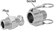
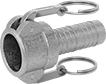
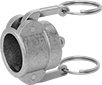
Made of ductile iron, these couplings are tough enough to handle sand, cement, and other abrasive solids and slurries. They resist impact and wear better than aluminum and brass couplings. Use their cam-and-groove fittings to quickly connect and disconnect medium- to large-diameter hose lines. To connect, insert the plug into the socket and press the levers down. The levers fit snugly into the groove on the plug’s body and force the plug against the gasket, forming a tight seal. To disconnect, lift both levers and pull out the plug. A complete coupling consists of a plug and a socket (both sold separately).
Plugs with male threaded end are also known as F adapters.
Plugs with female threaded end are also known as A adapters.
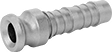
Plugs with barbed end are also known as E adapters. Insert the barbed end into plastic or rubber hose and secure with a clamp.
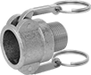
Sockets with male threaded end are also known as B couplers.
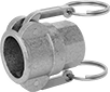
Sockets with female threaded end are also known as D couplers.
Sockets with barbed end are also known as C couplers. Insert the barbed end into plastic or rubber hose and secure with a clamp.
Note: To ensure a correct fit, make sure that the plug and socket have the same coupling size.
Warning: Relieve all pressure before disconnecting the couplings. Do not use cam-and-groove couplings with compressed air or gas.

- Maximum Pressure: See table
- Temperature Range: -20° to 250° F
- Specifications Met: Fed. Spec. A-A-59326
- Compatible With: Andrews Cam-and-Groove, Dixon Cam-and-Groove, PT Coupling Cam-and-Groove

- Maximum Pressure: See table
- Temperature Range: -20° to 250° F
- Specifications Met: Fed. Spec. A-A-59326
- Compatible With: Andrews Cam-and-Groove, Dixon Cam-and-Groove, PT Coupling Cam-and-Groove
- Maximum Pressure: See table
- Temperature Range: -20° to 250° F
- Attachment Type: Use Band-and-Buckle Clamps
- Specifications Met: Fed. Spec. A-A-59326
- Compatible With: Andrews Cam-and-Groove, Dixon Cam-and-Groove, PT Coupling Cam-and-Groove

- Maximum Pressure: See table
- Temperature Range: -20° to 250° F
- Specifications Met: Fed. Spec. A-A-59326
- Compatible With: Andrews Cam-and-Groove, Dixon Cam-and-Groove, PT Coupling Cam-and-Groove
Plugs | 6" Retaining Chains | 12" Retaining Chains | ||||||
|---|---|---|---|---|---|---|---|---|
| Coupling Size | Plug OD | Max. Pressure | Each | Each | Each | |||
Ductile Iron | ||||||||
| 1 | 1 7/16" | 250 psi @ 72° F | 0000000 | 000000 | 00000000 | 00000 | 00000000 | 00000 |
| 2 | 2 1/2" | 250 psi @ 72° F | 0000000 | 00000 | 00000000 | 0000 | 00000000 | 0000 |
| 3 | 3 5/8" | 200 psi @ 72° F | 0000000 | 00000 | 00000000 | 0000 | 00000000 | 0000 |
| 4 | 4 3/4" | 150 psi @ 72° F | 0000000 | 00000 | 00000000 | 0000 | 00000000 | 0000 |
- Maximum Pressure: See table
- Temperature Range: -20° to 250° F
- Specifications Met: Fed. Spec. A-A-59326
- Compatible With: Andrews Cam-and-Groove, Dixon Cam-and-Groove, PT Coupling Cam-and-Groove
Sockets | |||||||||||||||
|---|---|---|---|---|---|---|---|---|---|---|---|---|---|---|---|
Levers | Replacement Gaskets | Replacement Levers | Protective Plugs | ||||||||||||
| Coupling Size | Socket ID | Pipe Size | No. of | Material | Pull Ring Material | Max. Pressure | Each | Pkg. Qty. | Pkg. | Each | Each | ||||
Ductile Iron | |||||||||||||||
| 1 | 1 7/16" | 1 | 2 | 300 Series Stainless Steel | 300 Series Stainless Steel | 250 psi @ 72° F | 0000000 | 000000 | 10 | 0000000 | 00000 | 0000000 | 00000 | 000000 | 00 |
| 1 1/2 | 2 1/8" | 1 1/2 | 2 | 300 Series Stainless Steel | 300 Series Stainless Steel | 250 psi @ 72° F | 0000000 | 00000 | 10 | 0000000 | 0000 | 0000000 | 0000 | 000000 | 00 |
| 2 | 2 1/2" | 2 | 2 | 300 Series Stainless Steel | 300 Series Stainless Steel | 250 psi @ 72° F | 0000000 | 00000 | 10 | 0000000 | 0000 | 0000000 | 0000 | 00000000 | 000000 |
| 3 | 3 5/8" | 3 | 2 | 300 Series Stainless Steel | 300 Series Stainless Steel | 200 psi @ 72° F | 0000000 | 00000 | 10 | 0000000 | 00000 | 0000000 | 0000 | 00000000 | 00000 |
| 4 | 4 3/4" | 4 | 2 | 300 Series Stainless Steel | 300 Series Stainless Steel | 150 psi @ 72° F | 0000000 | 000000 | 10 | 0000000 | 00000 | 0000000 | 0000 | 00000000 | 00000 |
- Maximum Pressure: See table
- Temperature Range: -20° to 250° F
- Attachment Type: Use Band-and-Buckle Clamps
- Specifications Met: Fed. Spec. A-A-59326
- Compatible With: Andrews Cam-and-Groove, Dixon Cam-and-Groove, PT Coupling Cam-and-Groove
Sockets | |||||||||||||||
|---|---|---|---|---|---|---|---|---|---|---|---|---|---|---|---|
Levers | Replacement Gaskets | Replacement Levers | Protective Plugs | ||||||||||||
| Coupling Size | Socket ID | For Hose ID | No. of | Material | Pull Ring Material | Max. Pressure | Each | Pkg. Qty. | Pkg. | Each | Each | ||||
Ductile Iron | |||||||||||||||
| 1 | 1 7/16" | 1" | 2 | 300 Series Stainless Steel | 300 Series Stainless Steel | 250 psi @ 72° F | 0000000 | 000000 | 10 | 0000000 | 00000 | 0000000 | 00000 | 000000 | 00 |
| 1 1/2 | 2 1/8" | 1 1/2" | 2 | 300 Series Stainless Steel | 300 Series Stainless Steel | 250 psi @ 72° F | 0000000 | 00000 | 10 | 0000000 | 0000 | 0000000 | 0000 | 000000 | 00 |
| 2 | 2 1/2" | 2" | 2 | 300 Series Stainless Steel | 300 Series Stainless Steel | 250 psi @ 72° F | 0000000 | 00000 | 10 | 0000000 | 0000 | 0000000 | 0000 | 00000000 | 000000 |
| 3 | 3 5/8" | 3" | 2 | 300 Series Stainless Steel | 300 Series Stainless Steel | 200 psi @ 72° F | 0000000 | 00000 | 10 | 0000000 | 00000 | 0000000 | 0000 | 00000000 | 00000 |
| 4 | 4 3/4" | 4" | 2 | 300 Series Stainless Steel | 300 Series Stainless Steel | 150 psi @ 72° F | 0000000 | 000000 | 10 | 0000000 | 00000 | 0000000 | 0000 | 00000000 | 00000 |
- Maximum Pressure: See table
- Temperature Range: -20° to 250° F
- Specifications Met: Fed. Spec. A-A-59326
- Compatible With: Andrews Cam-and-Groove, Dixon Cam-and-Groove, PT Coupling Cam-and-Groove
Caps | |||||||||||
|---|---|---|---|---|---|---|---|---|---|---|---|
Levers | 6" Retaining Chains | 12" Retaining Chains | |||||||||
| Coupling Size | Socket ID | No. of | Material | Pull Ring Material | Max. Pressure | Each | Each | Each | |||
Ductile Iron | |||||||||||
| 1 | 1 7/16" | 2 | 300 Series Stainless Steel | 300 Series Stainless Steel | 250 psi @ 72° F | 0000000 | 000000 | 00000000 | 00000 | 00000000 | 00000 |
| 1 1/2 | 2 1/8" | 2 | 300 Series Stainless Steel | 300 Series Stainless Steel | 250 psi @ 72° F | 0000000 | 00000 | 00000000 | 0000 | 00000000 | 0000 |
| 2 | 2 1/2" | 2 | 300 Series Stainless Steel | 300 Series Stainless Steel | 250 psi @ 72° F | 0000000 | 00000 | 00000000 | 0000 | 00000000 | 0000 |
| 3 | 3 5/8" | 2 | 300 Series Stainless Steel | 300 Series Stainless Steel | 200 psi @ 72° F | 0000000 | 00000 | 00000000 | 0000 | 00000000 | 0000 |
| 4 | 4 3/4" | 2 | 300 Series Stainless Steel | 300 Series Stainless Steel | 150 psi @ 72° F | 0000000 | 00000 | 00000000 | 0000 | 00000000 | 0000 |
Fire Hydrants
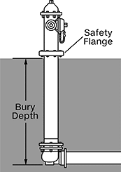
Fight fires in areas around your facility that city-installed hydrants don’t reach. These hydrants are dry-barrel, the most common type of hydrant, which means they drain water when not in use. Not only does this prevent freezing, but it keeps water from spurting out if a vehicle hits these hydrants. And if they get hit, they won’t need much repair—their safety flange and safety stem coupling break without shattering. That means the hydrant comes off cleanly, minimizing damage to the main body and stem. To repair, just replace the flange and coupling using the repair kit (sold separately).
These hydrants must be installed and maintained according to National Fire Protection Association (NFPA) Standards. If your main line is below 5 ft., attach a stem extension (sold separately). An extension can also raise your hydrant above the ground.
These hydrants are FM approved and meet AWWA C-502 standards for the durability, reliability, and safety of dry-barrel fire hydrants. Connect them to the plain end of a water main line with their mechanical joint connection. The fitting will maintain a tight seal through normal underground movement and temperature changes.
| Inlet Pipe Size | Fire Hose Trade Size (No. of Outlets) | Bury Dp., ft. | Ht. Above Ground | Drive Size | Drive Style | Valve Opening Direction | Body Material | Color | Fire Hydrant Valve Size | Operating Pressure, psi | Max. Temp., °F | Specifications Met | Each | |
Mechanical Joint Pipe Inlet × NH/NST Female Hose Outlet | ||||||||||||||
|---|---|---|---|---|---|---|---|---|---|---|---|---|---|---|
| 6 | 2 1/2 (2) 4 1/2 (1) | 5 | 32" | 1 1/2" | External Pentagon | Counterclockwise | Epoxy-Coated Ductile Iron | Red | 5 1/4" | 200 | 130° | AWWA C502, FM Approved | 0000000 | 000000000 |
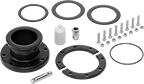
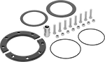
| Includes | Each | |
| Safety Stem Coupling, Safety Flange, Gasket, Mounting Hardware | 0000000 | 0000000 |