


Filter by

Maximum Pressure
Flow Control Type
Hydraulic Valve Default Position
Thread Type
Hydraulic Directional Control Valve Flow Pattern
Valve Function
Export Control Classification Number (ECCN)
DFARS Specialty Metals
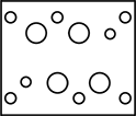
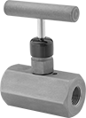
Flow-Adjustment Valve Manifolds for Hydraulic Jacks
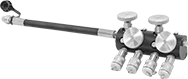 |
Pipe Size | Max. Pressure, psi | Material | Includes | Each | |||
|---|---|---|---|---|---|---|---|
NPTF Female | |||||||
| 3/8 | 10,000 | Steel | 18" Long Rubber Hose | 2983T31 | 000000000 | ||
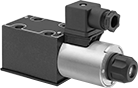
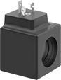
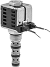
Solenoid-Operated Block-Mount Hydraulic Directional Control Valves
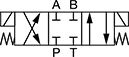
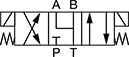
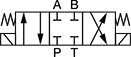
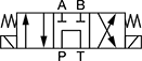
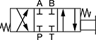
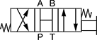
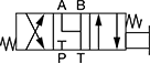
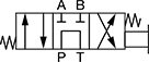
Single-Solenoid 4-Way Valves—2 Flow Positions (4/2 Valves)
 |  |  | 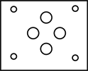 |  |
Style 1 | Style 2 | D03 Mounting Pattern | D05 Mounting Pattern |
Valves | Screws | |||||||||||
|---|---|---|---|---|---|---|---|---|---|---|---|---|
Style | NFPA Mounting Pattern | ISO Mounting Pattern | Max. Flow Rate, gpm | Max. Pressure, psi | Choose a Voltage | Each | Pkg. Qty. | Pkg. | ||||
Default Position P Open to A, B Open to T | ||||||||||||
| 1 | D03 | 03 | 20 | 5,000 | 12V DC, 24V DC, 120V AC | 49995K49 | 0000000 | 4 | 1945N12 | 00000 | ||
| 1 | D05 | 05 | 40 | 5,000 | 12V DC, 24V DC, 120V AC | 49995K59 | 000000 | 4 | 1945N15 | 0000 | ||
Default Position P Open to B, A Open to T | ||||||||||||
| 2 | D03 | 03 | 20 | 5,000 | 12V DC, 24V DC, 120V AC | 49995K58 | 000000 | 4 | 1945N12 | 0000 | ||
| 2 | D05 | 05 | 40 | 5,000 | 12V DC, 24V DC, 120V AC | 49995K67 | 000000 | 4 | 1945N15 | 0000 | ||
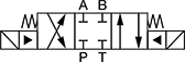
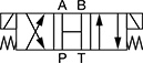
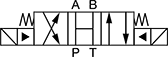
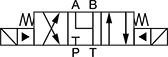
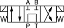
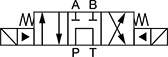
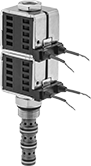
Double-Solenoid 4 Way Valves—3 Flow Positions (4/3 Valves)
 |  |  |  |
Style 3 | Style 4 | Style 5 | Style 6 |
 |  |  |  |
Style 7 | Style 8 | Style 9 | Style 10 |
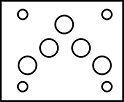
| |  | |
D03 Mounting Pattern | D05 Mounting Pattern | D08 Mounting Pattern |
Valves | Screws | |||||||||||
|---|---|---|---|---|---|---|---|---|---|---|---|---|
Style | NFPA Mounting Pattern | ISO Mounting Pattern | Max. Flow Rate, gpm | Max. Pressure, psi | Choose a Voltage | Each | Pkg. Qty. | Pkg. | ||||
Default Position Closed | ||||||||||||
| 3 | D03 | 03 | 20 | 5,000 | 12V DC, 24V DC, 120V AC | 49995K5 | 0000000 | 4 | 1945N12 | 00000 | ||
| 3 | D05 | 05 | 40 | 5,000 | 12V DC, 24V DC, 120V AC | 49995K9 | 000000 | 4 | 1945N15 | 0000 | ||
| 4 | D08 | 08 | 160 | 5,000 | 12V DC, 24V DC, 120V AC | 49995K27 | 00000000 | 6 | 1945N18 | 00000 | ||
Default Position Open | ||||||||||||
| 5 | D03 | 03 | 20 | 5,000 | 12V DC, 24V DC, 120V AC | 49995K6 | 000000 | 4 | 1945N12 | 0000 | ||
| 5 | D05 | 05 | 40 | 5,000 | 12V DC, 24V DC, 120V AC | 49995K17 | 000000 | 4 | 1945N15 | 0000 | ||
| 6 | D08 | 08 | 160 | 5,000 | 12V DC, 24V DC, 120V AC | 49995K29 | 00000000 | 6 | 1945N18 | 00000 | ||
Default Position P Closed, A and B Open to T | ||||||||||||
| 7 | D03 | 03 | 10 | 5,000 | 12V DC, 24V DC, 120V AC | 49995K7 | 000000 | 4 | 1945N12 | 0000 | ||
| 7 | D05 | 05 | 40 | 5,000 | 12V DC, 24V DC, 120V AC | 49995K18 | 000000 | 4 | 1945N15 | 0000 | ||
| 8 | D08 | 08 | 160 | 5,000 | 12V DC, 24V DC, 120V AC | 49995K47 | 00000000 | 6 | 1945N18 | 00000 | ||
Default Position P Open to T, A and B Closed | ||||||||||||
| 9 | D03 | 03 | 15 | 5,000 | 12V DC, 24V DC, 120V AC | 49995K8 | 000000 | 4 | 1945N12 | 0000 | ||
| 9 | D05 | 05 | 10 | 5,000 | 12V DC, 24V DC, 120V AC | 49995K19 | 000000 | 4 | 1945N15 | 0000 | ||
| 10 | D08 | 08 | 80 | 5,000 | 12V DC, 24V DC, 120V AC | 49995K48 | 00000000 | 6 | 1945N18 | 00000 | ||
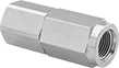
Screw-In Hydraulic Check Valves
Ball Check Valve
 |
Body—UN/UNF (SAE Straight) | |||||||||||||||
|---|---|---|---|---|---|---|---|---|---|---|---|---|---|---|---|
Deltrol Equivalent Model No. | Hydraforce Equivalent Model No. | Parker Equivalent Model No. | Thread Size | Dash Size | Max. Flow Rate, gpm | Flow Coefficient (Cv) | Max. Pressure, psi | Min. Opening Pressure, psi | Seal Material | Overall Ht. | Mounting Position | Each | |||
Black Anodized Aluminum Body | |||||||||||||||
| DCV-080-B-N-2 | — | — | 3/4"-16 | 08 | 5 | Not Rated | 3,000 | 2 | Buna-N | 1 1/4" | Any Angle | 1731N11 | 000000 | ||
| DCV-080-B-N-5 | — | — | 3/4"-16 | 08 | 5 | Not Rated | 3,000 | 5 | Buna-N | 1 1/4" | Any Angle | 1731N12 | 00000 | ||
| DCV-080-B-N-10 | CV08-20-0-N-10 | — | 3/4"-16 | 08 | 5 | Not Rated | 3,000 | 10 | Buna-N | 1 1/4" | Any Angle | 1731N13 | 00000 | ||
| DCV-080-B-N-25 | CV08-20-0-N-25 | — | 3/4"-16 | 08 | 5 | Not Rated | 3,000 | 25 | Buna-N | 1 1/4" | Any Angle | 1731N14 | 00000 | ||
| DCV-100-B-N-5 | CV10-20-0-N-05 | — | 7/8"-14 | 10 | 20 | Not Rated | 3,000 | 5 | Buna-N | 1 5/8" | Any Angle | 1731N15 | 00000 | ||
| DCV-100-B-N-15 | CV10-20-0-N-15 | D04B2-1.0-N | 7/8"-14 | 10 | 20 | Not Rated | 3,000 | 15 | Buna-N | 1 5/8" | Any Angle | 1731N17 | 00000 | ||
| DCV-100-B-N-30 | CV10-20-0-N-30 | — | 7/8"-14 | 10 | 20 | Not Rated | 3,000 | 30 | Buna-N | 1 5/8" | Any Angle | 1731N18 | 00000 | ||
| DCV-100-B-N-60 | — | D04B2-2.1-N | 7/8"-14 | 10 | 20 | Not Rated | 3,000 | 60 | Buna-N | 1 5/8" | Any Angle | 1731N19 | 00000 | ||
Adjustable Inline Hydraulic Flow-Regulating Valves
One Direction—NPTF Female
 |
One-direction valves regulate flow in one direction. They are not recommended for systems that may have reverse flow.
Inlet/Outlet Connection | Overall | |||||||||||||
|---|---|---|---|---|---|---|---|---|---|---|---|---|---|---|
Pipe Size | Dash Size | Max. Flow Rate, gpm | Flow Coefficient (Cv) | Max. Pressure, psi | Seal Material | Lg. | Wd. | Ht. | Port-to-Port Lg. | Valve Type | Each | |||
Steel Body | ||||||||||||||
| 1/4 | 04 | 3 | Not Rated | 3,000 | Buna-N | 3 5/8" | 1 3/8" | 2 3/4" | 3 5/8" | Needle | 1609N13 | 0000000 | ||
| 3/8 | 06 | 6 | Not Rated | 3,000 | Buna-N | 4 1/8" | 1 1/2" | 3 1/8" | 4 1/8" | Needle | 1609N14 | 000000 | ||
| 1/2 | 08 | 15 | Not Rated | 3,000 | Buna-N | 5" | 1 3/4" | 4" | 5" | Needle | 1609N15 | 000000 | ||
| 3/4 | 12 | 25 | Not Rated | 3,000 | Buna-N | 5 7/8" | 2 1/4" | 5 1/8" | 5 7/8" | Needle | 1609N11 | 000000 | ||
One Direction with Unrestricted Reverse—NPTF Female
|
One-direction-with-unrestricted-reverse valves regulate flow in one direction while allowing fluid to flow freely in the opposite direction.
Inlet/Outlet Connection | Overall | |||||||||||||
|---|---|---|---|---|---|---|---|---|---|---|---|---|---|---|
Pipe Size | Dash Size | Max. Flow Rate, gpm | Flow Coefficient (Cv) | Max. Pressure, psi | Seal Material | Lg. | Wd. | Ht. | Port-to-Port Lg. | Valve Type | Each | |||
Steel Body | ||||||||||||||
| 1/4 | 04 | 3 | Not Rated | 3,000 | Buna-N | 3 5/8" | 1 3/8" | 2 1/2" | 3 5/8" | Needle | 1381N13 | 0000000 | ||
| 3/8 | 06 | 6 | Not Rated | 3,000 | Buna-N | 4 1/8" | 1 1/2" | 2 7/8" | 4 1/8" | Needle | 1381N14 | 000000 | ||
| 1/2 | 08 | 15 | Not Rated | 3,000 | Buna-N | 5" | 1 3/4" | 3 3/4" | 5" | Needle | 1381N15 | 000000 | ||
| 3/4 | 12 | 25 | Not Rated | 3,000 | Buna-N | 5 7/8" | 2 1/4" | 4 5/8" | 5 7/8" | Needle | 1381N11 | 000000 | ||
| 1 | 16 | 50 | Not Rated | 3,000 | Buna-N | 7" | 2 3/4" | 6 1/4" | 7" | Needle | 1381N12 | 000000 | ||
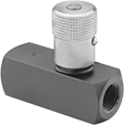
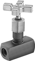
Flow-Adjustment Inline Hydraulic Valves
One Direction with Unrestricted Reverse—NPTF Female
|
One-direction-with-unrestricted-reverse valves regulate flow in one direction while allowing oil to flow freely in the opposite direction.
NPTF (Dryseal) threads are compatible with NPT threads.
Brass Body—Brass valves have better corrosion resistance than steel valves.
Inlet/Outlet Connection | Overall | |||||||||||||
|---|---|---|---|---|---|---|---|---|---|---|---|---|---|---|
Pipe Size | Dash Size | Max. Flow Rate, gpm | Flow Coefficient (Cv) | Max. Pressure, psi | Seal Material | Lg. | Wd. | Ht. | Port-to-Port Lg. | Valve Type | Each | |||
Steel Body | ||||||||||||||
| 1/8 | 02 | 3 | 0.23 | 5,000 | Buna-N | 2" | 3/4" | 1 3/4" | 2" | Needle | 1042K12 | 000000 | ||
| 1/4 | 04 | 5 | 0.43 | 5,000 | Buna-N | 2 5/8" | 7/8" | 2" | 2 5/8" | Needle | 1042K14 | 00000 | ||
| 3/8 | 06 | 8 | 0.79 | 5,000 | Buna-N | 2 3/4" | 1" | 2 1/2" | 2 3/4" | Needle | 1042K16 | 00000 | ||
| 1/2 | 08 | 15 | 0.98 | 5,000 | Buna-N | 3 1/2" | 1 1/4" | 3" | 3 1/2" | Needle | 1042K18 | 000000 | ||
| 3/4 | 12 | 25 | 2.47 | 3,000 | Buna-N | 3 7/8" | 1 1/2" | 3 5/8" | 3 7/8" | Needle | 1042K21 | 000000 | ||
| 1 | 16 | 40 | 5.25 | 3,000 | Buna-N | 5" | 1 7/8" | 5 1/8" | 5" | Needle | 1042K23 | 000000 | ||
Brass Body | ||||||||||||||
| 1/8 | 02 | 3 | 0.23 | 2,000 | Buna-N | 2" | 3/4" | 1 3/4" | 2" | Needle | 1042K11 | 00000 | ||
| 1/4 | 04 | 5 | 0.43 | 2,000 | Buna-N | 2 5/8" | 7/8" | 2" | 2 5/8" | Needle | 1042K13 | 00000 | ||
| 3/8 | 06 | 8 | 0.79 | 2,000 | Buna-N | 2 3/4" | 1" | 2 1/2" | 2 3/4" | Needle | 1042K15 | 00000 | ||
| 1/2 | 08 | 15 | 0.98 | 2,000 | Buna-N | 3 1/2" | 1 1/4" | 3" | 3 1/2" | Needle | 1042K17 | 000000 | ||
| 3/4 | 12 | 25 | 2.47 | 2,000 | Buna-N | 3 7/8" | 1 1/2" | 3 5/8" | 3 7/8" | Needle | 1042K19 | 000000 | ||
One Direction with Unrestricted Reverse—UN/UNF (SAE Straight) Female
|
One-direction-with-unrestricted-reverse valves regulate flow in one direction while allowing oil to flow freely in the opposite direction.
UN/UNF (SAE Straight) thread connections have straight threads and are also known as O-ring Boss fittings.
Inlet/Outlet Connection | Overall | |||||||||||||
|---|---|---|---|---|---|---|---|---|---|---|---|---|---|---|
Thread Size | Dash Size | Max. Flow Rate, gpm | Flow Coefficient (Cv) | Max. Pressure, psi | Seal Material | Lg. | Wd. | Ht. | Port-to-Port Lg. | Valve Type | Each | |||
Steel Body | ||||||||||||||
| 7/16"-20 | 04 | 3 | 0.23 | 5,000 | Buna-N | 2 3/4" | 7/8" | 1 7/8" | 2 3/4" | Needle | 1042K38 | 0000000 | ||
| 9/16"-18 | 06 | 5 | 0.43 | 5,000 | Buna-N | 3 1/8" | 1" | 2 1/4" | 3 1/8" | Needle | 1042K39 | 000000 | ||
| 3/4"-16 | 08 | 8 | 0.79 | 5,000 | Buna-N | 3 1/2" | 1 1/8" | 2 5/8" | 3 1/2" | Needle | 1042K41 | 000000 | ||
| 7/8"-14 | 10 | 15 | 0.98 | 5,000 | Buna-N | 4" | 1 1/4" | 3" | 4" | Needle | 1042K43 | 000000 | ||
| 1 1/16"-12 | 12 | 25 | 2.47 | 3,000 | Buna-N | 4 5/8" | 1 1/2" | 3 5/8" | 4 5/8" | Needle | 1042K44 | 000000 | ||
Two Direction—NPTF Female
|
Two-direction valves regulate flow in either direction.
NPTF (Dryseal) threads are compatible with NPT threads.
Brass Body—Brass valves have better corrosion resistance than steel valves.
Inlet/Outlet Connection | Overall | |||||||||||||
|---|---|---|---|---|---|---|---|---|---|---|---|---|---|---|
Pipe Size | Dash Size | Max. Flow Rate, gpm | Flow Coefficient (Cv) | Max. Pressure, psi | Seal Material | Lg. | Wd. | Ht. | Port-to-Port Lg. | Valve Type | Each | |||
Steel Body | ||||||||||||||
| 1/8 | 02 | 3 | 0.23 | 5,000 | Buna-N | 1 1/2" | 3/4" | 1 3/4" | 1 1/2" | Needle | 1535N12 | 000000 | ||
| 1/4 | 04 | 5 | 0.44 | 5,000 | Buna-N | 2" | 7/8" | 2" | 2" | Needle | 1535N14 | 00000 | ||
| 3/8 | 06 | 8 | 0.79 | 5,000 | Buna-N | 2 1/2" | 1" | 2 1/2" | 2 1/2" | Needle | 1535N16 | 00000 | ||
| 1/2 | 08 | 15 | 0.98 | 5,000 | Buna-N | 2 5/8" | 1 1/4" | 3" | 2 5/8" | Needle | 1535N18 | 000000 | ||
| 3/4 | 12 | 25 | 2.47 | 5,000 | Buna-N | 3 1/4" | 1 1/2" | 3 5/8" | 3 1/4" | Needle | 1535N21 | 000000 | ||
Brass Body | ||||||||||||||
| 1/8 | 02 | 3 | 0.23 | 2,000 | Buna-N | 1 1/2" | 3/4" | 1 3/4" | 1 1/2" | Needle | 1535N11 | 00000 | ||
| 1/4 | 04 | 5 | 0.44 | 2,000 | Buna-N | 2" | 7/8" | 2" | 2" | Needle | 1535N13 | 00000 | ||
| 3/8 | 06 | 8 | 0.79 | 2,000 | Buna-N | 2 1/2" | 1" | 2 1/2" | 2 1/2" | Needle | 1535N15 | 00000 | ||
| 1/2 | 08 | 15 | 0.98 | 2,000 | Buna-N | 2 5/8" | 1 1/4" | 3" | 2 5/8" | Needle | 1535N17 | 000000 | ||
| 3/4 | 12 | 25 | 2.47 | 2,000 | Buna-N | 3 1/4" | 1 1/2" | 3 5/8" | 3 1/4" | Needle | 1535N19 | 000000 | ||
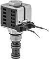
Screw-In Hydraulic Directional-Control Valves
Single-Solenoid 3-Way Valves—2 Flow Positions (3/2 Valves)
 |  |
Style 1 |
Place three-way valves between the pressure source and a single-acting cylinder.
Valves | Replacement Solenoid Coils | |||||||||||||
|---|---|---|---|---|---|---|---|---|---|---|---|---|---|---|
Body—UN/UNF (SAE Straight) | ||||||||||||||
Deltrol Equivalent Model No. | Hydraforce Equivalent Model No. | Parker Equivalent Model No. | Thread Size | Dash Size | Max. Flow Rate, gpm | Max. Pressure, psi | Voltage, V DC | Overall Ht. | Each | Each | ||||
Style 1—Default Position P Closed, A Open to T | ||||||||||||||
| DSV2-080-3B-N-D1DE | SV08-30-0-N-12EL | DSL083-B-N-SP-D012-L | 3/4"-16 | 08 | 5 | 3,000 | 12 | 3 9/16" | 1643N34 | 000000 | 1678N11 | 000000 | ||
| DSV2-080-3B-N-D2DE | SV08-30-0-N-24EL | DSL083-B-N-SP-D024-L | 3/4"-16 | 08 | 5 | 3,000 | 24 | 3 9/16" | 1643N35 | 00000 | 1678N12 | 00000 | ||
Single-Solenoid 4-Way Valves—2 Flow Positions (4/2 Valves)
 |
 |
Style 2 |
 |
Style 3 |
Place four-way valves between the pressure source and a double-acting cylinder.
Valves | Replacement Solenoid Coils | |||||||||||||
|---|---|---|---|---|---|---|---|---|---|---|---|---|---|---|
Body—UN/UNF (SAE Straight) | ||||||||||||||
Deltrol Equivalent Model No. | Hydraforce Equivalent Model No. | Parker Equivalent Model No. | Thread Size | Dash Size | Max. Flow Rate, gpm | Max. Pressure, psi | Voltage, V DC | Overall Ht. | Each | Each | ||||
Style 2—Default Position Closed | ||||||||||||||
| DSV2-080-4NC-N-D2DE | SV08-41-0-N-24EL | DSL084-N-N-DP-D024-L | 3/4"-16 | 08 | 3 | 3,000 | 24 | 4 1/16" | 1643N46 | 000000 | 1678N12 | 000000 | ||
Style 3—Default Position P Open to A, B Open to T | ||||||||||||||
| DSV2-100-4CO-N-D1D | SV10-40-0-N-12DL | DSL104-B-N-D012-L | 7/8"-14 | 10 | 6 | 3,000 | 12 | 4 7/8" | 1643N43 | 000000 | 1678N13 | 00000 | ||
Double-Solenoid 4 Way Valves—3 Flow Positions (4/3 Valves)
 |
 |
Style 4 |
 |
Style 5 |
Place four-way valves between the pressure source and a double-acting cylinder.
Valves | Replacement Solenoid Coils | ||||||||||||
|---|---|---|---|---|---|---|---|---|---|---|---|---|---|
Body—UN/UNF (SAE Straight) | |||||||||||||
Deltrol Equivalent Model No. | Hydraforce Equivalent Model No. | Thread Size | Dash Size | Max. Flow Rate, gpm | Max. Pressure, psi | Voltage, V DC | Overall Ht. | Each | Each | ||||
Style 4—Default Position Closed | |||||||||||||
| DSV-080-34C-N-D1DE | SV08-47C-0-N-12EL | 3/4"-16 | 08 | 3 | 3,000 | 12 | 5 1/2" | 1643N62 | 0000000 | 1678N11 | 000000 | ||
Style 5—Default Position P Open to T, A and B Closed | |||||||||||||
| DSV-080-34T-N-D1DE | SV08-47A-0-N-12EL | 3/4"-16 | 08 | 3 | 3,000 | 12 | 5 1/2" | 1643N78 | 000000 | 1678N11 | 00000 | ||
| DSV-080-34T-N-D2DE | SV08-47A-0-N-24EL | 3/4"-16 | 08 | 3 | 3,000 | 24 | 5 1/2" | 1643N79 | 000000 | 1678N12 | 00000 | ||
Flow-Adjustment Valves for Hydraulic Jacks
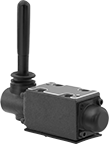
Toggle-Operated Block-Mount Hydraulic Directional Control Valves
 |
 |  |  |
Style 1 | Style 2 | Style 3 |
 | | |
Style 4 | D03 Mounting Pattern | D05 Mounting Pattern |
Valves | Screws | |||||||||||||
|---|---|---|---|---|---|---|---|---|---|---|---|---|---|---|
Overall | ||||||||||||||
Style | NFPA Mounting Pattern | ISO Mounting Pattern | Max. Flow Rate, gpm | Max. Pressure, psi | Lg. | Wd. | Ht. | Each | Pkg. Qty. | Pkg. | ||||
4-Way Valves—3 Flow Positions (4/3 Valves) | ||||||||||||||
Default Position Closed | ||||||||||||||
| 1 | D03 | 03 | 22 | 5,000 | 5 7/8" | 1 7/8" | 6" | 4393T411 | 0000000 | 4 | 1945N12 | 00000 | ||
| 1 | D05 | 05 | 40 | 5,000 | 6 7/8" | 2 3/4" | 6 3/8" | 4393T415 | 00000000 | 4 | 1945N15 | 0000 | ||
Default Position Open | ||||||||||||||
| 2 | D03 | 03 | 22 | 5,000 | 5 7/8" | 1 7/8" | 6" | 4393T412 | 000000 | 4 | 1945N12 | 0000 | ||
Default Position P Closed, A and B Open to T | ||||||||||||||
| 3 | D03 | 03 | 12 | 5,000 | 5 7/8" | 1 7/8" | 6" | 4393T413 | 000000 | 4 | 1945N12 | 0000 | ||
| 3 | D05 | 05 | 40 | 5,000 | 6 7/8" | 2 3/4" | 6 3/8" | 4393T417 | 00000000 | 4 | 1945N15 | 0000 | ||
Default Position P Open to T, A and B Closed | ||||||||||||||
| 4 | D03 | 03 | 12 | 5,000 | 5 7/8" | 1 7/8" | 6" | 4393T414 | 000000 | 4 | 1945N12 | 0000 | ||
| 4 | D05 | 05 | 13 | 5,000 | 6 7/8" | 2 3/4" | 6 3/8" | 4393T418 | 00000000 | 4 | 1945N15 | 0000 | ||
Inline Hydraulic Flow-Regulating Valves
One Direction with Unrestricted Reverse—NPTF Female
 |
NPTF (Dryseal) threads are compatible with NPT threads.
Inlet/Outlet Connection | ||||||||||||
|---|---|---|---|---|---|---|---|---|---|---|---|---|
Pipe Size | Dash Size | Flow Coefficient (Cv) | Max. Pressure, psi | Seal Material | Port-to-Port Lg. | Valve Type | Hex Wd. | Choose a Flow Rate, gpm | Each | |||
Steel Body | ||||||||||||
| 1/4 | 04 | Not Rated | 3,500 | Buna-N | 2 1/2" | Piston | 15/16" | 0.5, 1, 1.5, 2, 2.5, 3, 3.5, 4 | 2301N91 | 000000 | ||
| 3/8 | 06 | Not Rated | 3,500 | Buna-N | 2 1/2" | Piston | 15/16" | 0.5, 1, 1.5, 2, 2.5, 3, 3.5, 4, 4.5, 5 | 2301N92 | 00000 | ||
| 1/2 | 08 | Not Rated | 3,500 | Buna-N | 2 7/8" | Piston | 1 1/16" | 1, 1.5, 2, 2.5, 3, 3.5, 4, 4.5, 5, 6, 7, 8, 9, 10 | 2301N93 | 00000 | ||
One Direction with Unrestricted Reverse—UN/UNF (SAE Straight) Female
|
UN/UNF (SAE Straight) thread connections have straight threads and are also known as O-ring Boss fittings.
Inlet/Outlet Connection | ||||||||||||
|---|---|---|---|---|---|---|---|---|---|---|---|---|
Thread Size | Dash Size | Flow Coefficient (Cv) | Max. Pressure, psi | Seal Material | Port-to-Port Lg. | Valve Type | Hex Wd. | Choose a Flow Rate, gpm | Each | |||
Steel Body | ||||||||||||
| 7/16"-20 | 04 | Not Rated | 3,500 | Buna-N | 2 1/4" | Piston | 3/4" | 0.5, 1, 1.5, 2, 2.5, 3, 3.5, 4 | 2301N94 | 000000 | ||
| 9/16"-18 | 06 | Not Rated | 3,500 | Buna-N | 2 1/2" | Piston | 15/16" | 0.5, 1, 1.5, 2, 2.5, 3, 3.5, 4, 4.5, 5 | 2301N95 | 00000 | ||
| 3/4"-16 | 08 | Not Rated | 3,500 | Buna-N | 2 7/8" | Piston | 1 1/16" | 0.5, 1, 1.5, 2, 2.5, 3, 3.5, 4, 4.5, 5, 6, 7, 8, 9, 10 | 2301N96 | 000000 | ||
Precision Flow-Adjustment Inline Hydraulic Valves
Two Direction—NPTF Female
 |
NPTF (Dryseal) threads are compatible with NPT threads.
Inlet/Outlet Connection | Overall | |||||||||||||
|---|---|---|---|---|---|---|---|---|---|---|---|---|---|---|
Pipe Size | Dash Size | Max. Flow Rate, gpm | Flow Coefficient (Cv) | Max. Pressure, psi | Seal Material | Lg. | Wd. | Ht. | Port-to-Port Lg. | Valve Type | Each | |||
Steel Body | ||||||||||||||
| 1/8 | 02 | 3 | 0.24 | 5,000 | Buna-N | 1 1/2" | 1 3/4" | 3" | 1 1/2" | Needle | 1042K25 | 0000000 | ||
| 1/4 | 04 | 5 | 0.49 | 5,000 | Buna-N | 2" | 2" | 3 7/8" | 2" | Needle | 1042K27 | 00000 | ||
| 3/8 | 06 | 8 | 1.29 | 5,000 | Buna-N | 2 1/2" | 2 1/2" | 4 3/8" | 2 1/2" | Needle | 1042K31 | 000000 | ||
| 1/2 | 08 | 15 | 1.93 | 5,000 | Buna-N | 2 5/8" | 3 1/4" | 5 3/4" | 2 5/8" | Needle | 1042K34 | 000000 | ||
| 3/4 | 12 | 25 | 3.21 | 5,000 | Buna-N | 3 1/4" | 3 7/8" | 6 3/8" | 3 1/4" | Needle | 1042K36 | 000000 | ||
Two Direction—UN/UNF (SAE Straight) Female
|
UN/UNF (SAE Straight) thread connections have straight threads and are also known as O-ring Boss fittings.
Inlet/Outlet Connection | Overall | |||||||||||||
|---|---|---|---|---|---|---|---|---|---|---|---|---|---|---|
Thread Size | Dash Size | Max. Flow Rate, gpm | Flow Coefficient (Cv) | Max. Pressure, psi | Seal Material | Lg. | Wd. | Ht. | Port-to-Port Lg. | Valve Type | Each | |||
Steel Body | ||||||||||||||
| 7/16"-20 | 04 | 3 | 0.24 | 5,000 | Buna-N | 2" | 1 3/4" | 3 1/4" | 2" | Needle | 1042K28 | 0000000 | ||
| 9/16"-18 | 06 | 5 | 0.49 | 5,000 | Buna-N | 2 3/8" | 2" | 4" | 2 3/8" | Needle | 1042K32 | 000000 | ||
| 3/4"-16 | 08 | 8 | 1.29 | 5,000 | Buna-N | 3" | 2 1/2" | 4 7/8" | 3" | Needle | 1042K35 | 000000 | ||
| 1 1/16"-12 | 12 | 25 | 3.21 | 5,000 | Buna-N | 4" | 3 7/8" | 6 3/8" | 4" | Needle | 1042K37 | 000000 | ||
Screw-In Hydraulic Flow-Adjustment Valves
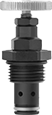 |
Turn the knob to gradually adjust the amount of flow. These compact valves screw into your mounting block. They are also known as needle valves and cartridge valves.
Body | ||||||||||||||
|---|---|---|---|---|---|---|---|---|---|---|---|---|---|---|
Deltrol Equivalent Model No. | Hydraforce Equivalent Model No. | Parker Equivalent Model No. | Thread Size | Dash Size | Max. Flow Rate, gpm | Flow Coefficient (Cv) | Max. Pressure, psi | Seal Material | Overall Ht. | Valve Type | Each | |||
Two Direction—UN/UNF (SAE Straight) | ||||||||||||||
Black Anodized Aluminum Body | ||||||||||||||
| DNV-080-N-K | NV08-20B-0-N | NVH081-K-N | 3/4"-16 | 08 | 12 | 0.47 | 3,000 | Buna-N | 2 3/8" | Needle | 1599N11 | 000000 | ||
| DNV-100-N-K | NV10-20B-0-N | NVH101-K-N | 7/8"-14 | 10 | 12 | 1.25 | 3,000 | Buna-N | 2 5/8" | Needle | 1599N12 | 00000 | ||
