


Filter by
System of Measurement
Bore Diameter

Actuation Type
Rod End Type
Hydraulic Cylinder Body Style
For Use With
Rod Diameter
Maximum Push Force
Maximum Pressure
Maximum Pull Force
Rod Thread Size
DFARS Specialty Metals
Export Control Classification Number (ECCN)
RoHS
REACH
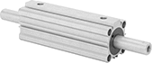
Double-Ended Compact Hydraulic Cylinders
 |
 |
Push one heavy load while pulling another. These hydraulic cylinders have a rod that runs through both ends, so when it extends on one end, it retracts on the other. Built with a small body, they'll fit in tight spaces but operate with similar force to standard-sized hydraulic cylinders. This is in large part thanks to their two hydraulic ports: one port to extend the rod and another port to retract it. That means no matter which direction they're moving, they're giving it the same amount of power.
The piston is magnetic, so you can use these cylinders with sensors (sold separately) to activate relays and controllers. When the piston moves past a sensor, the sensor activates. You can use multiple sensors—one for each action you want to trigger.
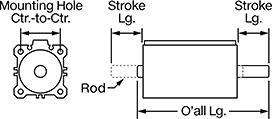
Rod | O'all | Mounting Hole | Inlet/Outlet Connection | ||||||||||||||||
|---|---|---|---|---|---|---|---|---|---|---|---|---|---|---|---|---|---|---|---|
Stroke Lg. | Body Lg. | Max. Push Force, lbf | Max. Pull Force, lbf | Thread Size | Dia. | Wd. | Lg. | Ht. | Ctr.-to-Ctr. | Dia. | Pipe Size | Thread Type | Body Material | Max. Pressure, psi | Cylinder Cushion Type | Each | |||
1 1/4" Diameter Bore | |||||||||||||||||||
| 1" | 2 1/2" | 470 | 470 | M10 × 1.5 mm | 5/8" | 1 3/4" | 5 1/4" | 1 3/4" | 1 5/16" | 7/32" | 1/8 | BSPT | Aluminum | 500 | None | 6443N14 | 0000000 | ||
| 2" | 2 1/2" | 470 | 470 | M10 × 1.5 mm | 5/8" | 1 3/4" | 7 1/8" | 1 3/4" | 1 5/16" | 7/32" | 1/8 | BSPT | Aluminum | 500 | None | 6443N15 | 000000 | ||
| 3" | 2 1/2" | 470 | 470 | M10 × 1.5 mm | 5/8" | 1 3/4" | 9 1/8" | 1 3/4" | 1 5/16" | 7/32" | 1/8 | BSPT | Aluminum | 500 | None | 6443N16 | 000000 | ||
| 4" | 2 1/2" | 470 | 470 | M10 × 1.5 mm | 5/8" | 1 3/4" | 11 1/8" | 1 3/4" | 1 5/16" | 7/32" | 1/8 | BSPT | Aluminum | 500 | None | 6443N17 | 000000 | ||
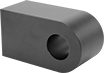
Hydraulic Cylinder Flat-Shoulder Rod Ends
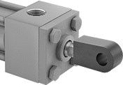 |  | 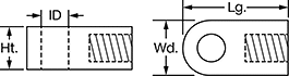 |
Rod End Installed on Hydraulic Cylinder |
For Bore Dia. | ID | Thread Size | Lg. | Wd. | Ht. | Gender | For Hydraulic Cylinder Mounting Pattern | Each | |||
|---|---|---|---|---|---|---|---|---|---|---|---|
Steel | |||||||||||
| 1 1/4" | 1 3/8" | 1 1/4"-12 | 4 13/16" | 2 3/4" | 2" | Female | NFPA Light Duty, NFPA/JIC Heavy Duty | 6466N14 | 000000 | ||
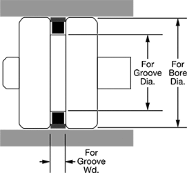
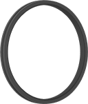
High-Speed Piston Seals
 |  | |
Profile |
For Groove | O-Ring | ||||||||||||||
|---|---|---|---|---|---|---|---|---|---|---|---|---|---|---|---|
For Bore Dia. | Dia. | Wd. | O-Ring Dash No. Equiv. | Max. Speed, ft/sec | Max. Pressure, psi | Temp. Range, ° F | Hardness | Color | Hardness | Color | Specs. Met | Each | |||
Glass-Filled PTFE with Buna-N O-Ring | |||||||||||||||
| 1 1/4" | 0.990" | 0.083" | 022 | 12 | 8,500 | -30 to 230 | Durometer 60D (Extra Hard) | Gold | Durometer 70A (Hard) | Black | ANSI B93.32, NFPA T3.19.18 | 1526N15 | 00000 | ||
High-Stability High-Speed Piston Seals
 |  | |
Profile |
For Groove | O-Ring | ||||||||||||||
|---|---|---|---|---|---|---|---|---|---|---|---|---|---|---|---|
For Bore Dia. | Dia. | Wd. | O-Ring Dash No. Equiv. | Max. Speed, ft/sec | Max. Pressure, psi | Temp. Range, ° F | Hardness | Color | Hardness | Color | Specs. Met | Each | |||
Glass-Filled PTFE with Buna-N O-Ring | |||||||||||||||
| 1 1/4" | 0.942" | 0.129" | 119 | 12 | 8,500 | -30 to 230 | Durometer 60D (Extra Hard) | Blue | Durometer 70A (Hard) | Black | ANSI B93.32, NFPA T3.19.18 | 1716N12 | 00000 | ||
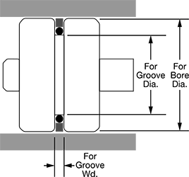
Piston Seals for O-Ring Grooves
 |  | |
Profile |
For Groove | ||||||||||||
|---|---|---|---|---|---|---|---|---|---|---|---|---|
For Bore Dia. | Dia. | Wd. | O-Ring Dash No. Equiv. | Max. Speed, ft/sec | Max. Pressure, psi | Temp. Range, ° F | Hardness | Color | Each | |||
Buna-N with Nylon Backup Ring | ||||||||||||
| 1 1/4" | 1.007" | 0.187" | 214 | 1.6 | 5,000 | -40 to 225 | Durometer 70A (Hard) | Black | 1386N17 | 00000 | ||
