


Filter by
For Use With
Maximum Flow Rate
Maximum Pressure
Power Source
Fixed Displacement Rate
Maximum Temperature
Drive Direction


Housing Material

Priming Type
DFARS Specialty Metals
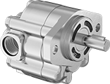
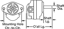
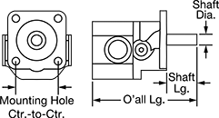
Hydraulic Gear Pumps
SAE AA—3 1/4" Mounting Hole Center-to-Center
 |  |
UN/UNF (SAE Straight) Thread—UN/UNF (SAE Straight) thread connections have straight threads and are also known as O-ring Boss fittings.
Inlet Connection | Outlet Connection | Overall | Shaft | |||||||||||||||
|---|---|---|---|---|---|---|---|---|---|---|---|---|---|---|---|---|---|---|
Fixed Displacement Rate, in³/rev | Max. Flow Rate | Max. Pressure, psi | Max. Rotation Speed, rpm | Thread Size | Thread Type | Dash Size | Thread Size | Thread Type | Dash Size | Lg. | Ht. | Dia. | Lg. | Choose a Drive Direction | Each | |||
| 0.11 | 1.7 gpm | 2,500 | 4,000 | 7/8"-14 | UN/UNF (SAE Straight) | 10 | 3/4"-16 | UN/UNF (SAE Straight) | 08 | 4" | 3 5/8" | 1/2" | 1 1/4" | Clockwise, Counterclockwise | 6296K44 | 0000000 | ||
| 0.21 | 3.3 gpm | 2,500 | 4,000 | 7/8"-14 | UN/UNF (SAE Straight) | 10 | 3/4"-16 | UN/UNF (SAE Straight) | 08 | 4 1/4" | 3 5/8" | 1/2" | 1 1/4" | Clockwise, Counterclockwise | 6296K45 | 000000 | ||
| 0.33 | 5.2 gpm | 2,500 | 4,000 | 7/8"-14 | UN/UNF (SAE Straight) | 10 | 3/4"-16 | UN/UNF (SAE Straight) | 08 | 4 3/8" | 3 5/8" | 1/2" | 1 1/4" | Clockwise, Counterclockwise | 6296K47 | 000000 | ||
| 0.52 | 8.4 gpm | 2,500 | 4,000 | 7/8"-14 | UN/UNF (SAE Straight) | 10 | 3/4"-16 | UN/UNF (SAE Straight) | 08 | 4 3/4" | 3 5/8" | 1/2" | 1 1/4" | Clockwise, Counterclockwise | 6296K53 | 000000 | ||
| 0.64 | 7.8 gpm | 2,000 | 3,000 | 7/8"-14 | UN/UNF (SAE Straight) | 10 | 3/4"-16 | UN/UNF (SAE Straight) | 08 | 4 7/8" | 3 5/8" | 1/2" | 1 1/4" | Clockwise, Counterclockwise | 6296K55 | 000000 | ||
SAE A—4 3/16" Mounting Hole Center-to-Center
 | |
UN/UNF (SAE Straight) Thread—UN/UNF (SAE Straight) thread connections have straight threads and are also known as O-ring Boss fittings.
Inlet Connection | Outlet Connection | Overall | Shaft | |||||||||||||||
|---|---|---|---|---|---|---|---|---|---|---|---|---|---|---|---|---|---|---|
Fixed Displacement Rate, in³/rev | Max. Flow Rate | Max. Pressure, psi | Max. Rotation Speed, rpm | Thread Size | Thread Type | Dash Size | Thread Size | Thread Type | Dash Size | Lg. | Ht. | Dia. | Lg. | Choose a Drive Direction | Each | |||
| 0.37 | 5.9 gpm | 4,000 | 4,000 | 7/8"-14 | UN/UNF (SAE Straight) | 10 | 3/4"-16 | UN/UNF (SAE Straight) | 08 | 4 7/8" | 4 5/8" | 3/4" | 1" | Clockwise, Counterclockwise | 6296K25 | 0000000 | ||
| 0.49 | 7.9 gpm | 4,000 | 4,000 | 1 1/16"-12 | UN/UNF (SAE Straight) | 12 | 7/8"-14 | UN/UNF (SAE Straight) | 10 | 5" | 4 5/8" | 3/4" | 1" | Clockwise, Counterclockwise | 6296K26 | 000000 | ||
| 0.61 | 9.9 gpm | 4,000 | 4,000 | 1 1/16"-12 | UN/UNF (SAE Straight) | 12 | 7/8"-14 | UN/UNF (SAE Straight) | 10 | 5 1/8" | 4 5/8" | 3/4" | 1" | Clockwise, Counterclockwise | 6296K27 | 000000 | ||
| 0.98 | 11.9 gpm | 4,000 | 3,000 | 1 1/16"-12 | UN/UNF (SAE Straight) | 12 | 7/8"-14 | UN/UNF (SAE Straight) | 10 | 5 1/2" | 4 5/8" | 3/4" | 1" | Clockwise, Counterclockwise | 6296K28 | 000000 | ||
| 1.16 | 14.1 gpm | 4,000 | 3,000 | 1 5/16"-12 | UN/UNF (SAE Straight) | 16 | 1 1/16"-12 | UN/UNF (SAE Straight) | 12 | 5 5/8" | 4 5/8" | 3/4" | 1" | Clockwise, Counterclockwise | 6296K29 | 000000 | ||
| 1.4 | 15.9 gpm | 3,200 | 2,800 | 1 5/16"-12 | UN/UNF (SAE Straight) | 16 | 1 1/16"-12 | UN/UNF (SAE Straight) | 12 | 5 7/8" | 4 5/8" | 3/4" | 1" | Clockwise, Counterclockwise | 6296K37 | 000000 | ||
| 1.65 | 16.1 gpm | 2,700 | 2,400 | 1 5/16"-12 | UN/UNF (SAE Straight) | 16 | 1 1/16"-12 | UN/UNF (SAE Straight) | 12 | 6 1/8" | 4 5/8" | 3/4" | 1" | Clockwise, Counterclockwise | 6296K38 | 000000 | ||
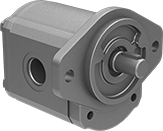
SAE B—5 3/4" Mounting Hole Center-to-Center
 | |
UN/UNF (SAE Straight) Thread—UN/UNF (SAE Straight) thread connections have straight threads and are also known as O-ring Boss fittings.
Inlet Connection | Outlet Connection | Overall | Shaft | |||||||||||||||
|---|---|---|---|---|---|---|---|---|---|---|---|---|---|---|---|---|---|---|
Fixed Displacement Rate, in³/rev | Max. Flow Rate | Max. Pressure, psi | Max. Rotation Speed, rpm | Thread Size | Thread Type | Dash Size | Thread Size | Thread Type | Dash Size | Lg. | Ht. | Dia. | Lg. | Choose a Drive Direction | Each | |||
| 2.01 | 24.5 gpm | 4,000 | 3,000 | 1 5/8"-12 | UN/UNF (SAE Straight) | 20 | 1 5/16"-12 | UN/UNF (SAE Straight) | 16 | 7 1/8" | 5 7/8" | 7/8" | 1 1/4" | Clockwise, Counterclockwise | 6296K39 | 0000000 | ||
| 2.32 | 28.3 gpm | 4,000 | 3,000 | 1 5/8"-12 | UN/UNF (SAE Straight) | 20 | 1 5/16"-12 | UN/UNF (SAE Straight) | 16 | 7 3/8" | 5 7/8" | 7/8" | 1 1/4" | Clockwise | 6296K73 | 000000 | ||
| 3.05 | 33.5 gpm | 2,900 | 2,700 | 1 5/8"-12 | UN/UNF (SAE Straight) | 20 | 1 5/16"-12 | UN/UNF (SAE Straight) | 16 | 7 3/4" | 5 7/8" | 7/8" | 1 1/4" | Clockwise, Counterclockwise | 6296K59 | 000000 | ||
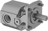
SAE 4F17—2" Mounting Hole Center-to-Center
 |  |
Inlet Connection | Outlet Connection | Overall | Shaft | |||||||||||||||
|---|---|---|---|---|---|---|---|---|---|---|---|---|---|---|---|---|---|---|
Fixed Displacement Rate, in³/rev | Max. Flow Rate | Max. Pressure, psi | Max. Rotation Speed, rpm | Thread Size | Thread Type | Dash Size | Thread Size | Thread Type | Dash Size | Lg. | Ht. | Dia. | Lg. | Drive Direction | Each | |||
| 0.07 | 0.8 gpm | 3,000 | 4,000 | 9/16"-18 | UN/UNF (SAE Straight) | 06 | 9/16"-18 | UN/UNF (SAE Straight) | 06 | 4 5/8" | 3 7/16" | 1/2" | 1 3/8" | Clockwise, Counterclockwise | 6296K51 | 0000000 | ||
| 0.13 | 1.7 gpm | 3,000 | 4,000 | 3/4"-16 | UN/UNF (SAE Straight) | 08 | 3/4"-16 | UN/UNF (SAE Straight) | 08 | 4 5/8" | 3 7/16" | 1/2" | 1 3/8" | Clockwise, Counterclockwise | 6296K71 | 000000 | ||
| 0.39 | 5 gpm | 3,000 | 4,000 | 7/8"-14 | UN/UNF (SAE Straight) | 10 | 7/8"-14 | UN/UNF (SAE Straight) | 10 | 5 1/8" | 3 7/16" | 1/2" | 1 3/8" | Clockwise, Counterclockwise | 6296K54 | 000000 | ||
| 0.71 | 5.4 gpm | 1,800 | 2,400 | 7/8"-14 | UN/UNF (SAE Straight) | 10 | 7/8"-14 | UN/UNF (SAE Straight) | 10 | 5 5/8" | 3 7/16" | 1/2" | 1 3/8" | Clockwise, Counterclockwise | 6296K56 | 000000 | ||
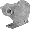
Constant-Flow-Rate Gear Pumps without Motor for Oil
 |
A cast iron housing and steel gears allow these gear pumps to be used to dispense oil and fuel such as hydraulic oil and diesel fuel. Select your own motor to tailor them to your application. Use an air or electric motor with a coupling and belt/pulley drive. They produce a smooth flow of liquid for applications such as engine lubrication. All are self-priming, which means they create a suction force to draw liquid upward and fill the pump chamber. Do not use with solids.
Note: Pumps must be filled with liquid before use. They need a constant flow of liquid and cannot run dry.
Required hp, hp | Intake (NPT) | Discharge (NPT) | Overall | Shaft | |||||||||||||||||||
|---|---|---|---|---|---|---|---|---|---|---|---|---|---|---|---|---|---|---|---|---|---|---|---|
Max. Flow Rate @ 25 psi, gpm | Max. Flow Rate | Max. ft. of Head, ft. | Max. Pressure, psi | Max. Viscosity, cP | Temp. Range, ° F | @ 25 psi | @ 100 psi | Pipe Size | Connection | Gender | Pipe Size | Connection | Gender | Lg. | Wd. | Ht. | Dia. | Lg. | Ctr.-to-Base Lg. | Each | |||
For 1,725 rpm Maximum Motor Speed | |||||||||||||||||||||||
| 8.9 | 9 gpm | 462 | 200 | 20,000 | -20 to 400 | 3/4 | 1 | 1/2 | Threaded | Female | 1/2 | Threaded | Female | 7 1/4" | 3 7/16" | 4 1/2" | 5/8" | 1 9/16" | 3" | 41915K72 | 000000000 | ||
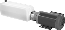
Constant-Flow-Rate Gear Pumps for Oil
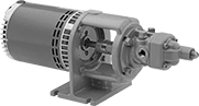 |
A high-horsepower motor moves oil with a viscosity similar to SAE 60 motor oil. These gear pumps produce a smooth flow of liquid to lubricate equipment and blend oils. Motor is open dripproof (ODP) for use in clean, dry, and well-ventilated environments. Pumps are gravity fed and require an elevated liquid source to fully fill the pump before turning on. Do not run dry or use with solids.
Note: If flow control is needed, place valves or reducers on the discharge side; never restrict the inlet of a pump with a valve or reducer.
Cannot Be Sold Outside North America—Products cannot be sold outside North America due to restrictions.
Intake (NPT) | Discharge (NPT) | Overall | ||||||||||||||||||
|---|---|---|---|---|---|---|---|---|---|---|---|---|---|---|---|---|---|---|---|---|
Max. Flow Rate | Max. ft. of Head, ft. | Max. Pressure, psi | Max. Viscosity, cP | Temp. Range, ° F | Power, hp | Current | Pipe Size | Connection | Gender | Pipe Size | Connection | Gender | Lg. | Wd. | Ht. | Cannot Be Sold To | Each | |||
240V AC/460V AC, Three Phase—Without Thermal Overload Protection | ||||||||||||||||||||
Hardwire | ||||||||||||||||||||
| 5 gpm | 577 | 250 | 880 | -20 to 240 | 1/2 | 2 amp/1 amp | 1/2 | Threaded | Female | 1/2 | Threaded | Female | 21 5/8" | 6 7/8" | 8 1/2" | Outside North America | 41505K41 | 000000000 | ||
208V AC to 240V AC/460V AC, Three Phase—Without Thermal Overload Protection | ||||||||||||||||||||
Hardwire | ||||||||||||||||||||
| 10 gpm | 577 | 250 | 880 | -20 to 240 | 2 | 6.2 amp/3.1 amp | 3/4 | Threaded | Female | 3/4 | Threaded | Female | 24" | 6 7/8" | 8 1/2" | Outside North America | 41505K43 | 00000000 | ||
| 20 gpm | 577 | 250 | 880 | -20 to 240 | 2 | 6.2 amp/3.1 amp | 1 | Threaded | Female | 1 | Threaded | Female | 24 1/2" | 6 7/8" | 8 1/2" | Outside North America | 41505K45 | 00000000 | ||
| 30 gpm | 577 | 250 | 880 | -20 to 240 | 3 | 8.2 amp/4.1 amp | 1 | Threaded | Female | 1 | Threaded | Female | 25" | 6 7/8" | 8 1/2" | Outside North America | 41505K47 | 00000000 | ||
| 40 gpm | 577 | 250 | 880 | -20 to 240 | 5 | 13.8 amp/6.9 amp | 1 1/2 | Threaded | Female | 1 1/2 | Threaded | Female | 28 1/8" | 11 7/8" | 8 1/2" | Outside North America | 41505K49 | 00000000 | ||
Constant-Flow-Rate Gear Pumps without Motor for Chemicals
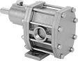 |
With a 316 stainless steel housing and stainless steel gears, these gear pumps are often used to dispense chemicals such as ethylene glycol, isopropyl alcohol, and nitric acid. Use an electric motor with a coupling and belt/pulley drive. They produce a smooth flow of liquid. All are self-priming, which means they create a suction force to draw liquid upward and fill the pump chamber. Do not use with solids.
Required hp, hp | Intake (NPT) | Discharge (NPT) | Overall | Shaft | |||||||||||||||||||
|---|---|---|---|---|---|---|---|---|---|---|---|---|---|---|---|---|---|---|---|---|---|---|---|
Max. Flow Rate @ 25 psi, gpm | Max. Flow Rate | Max. ft. of Head, ft. | Max. Pressure, psi | Max. Viscosity, cP | Temp. Range, ° F | @ 25 psi | @ 100 psi | Pipe Size | Connection | Gender | Pipe Size | Connection | Gender | Lg. | Wd. | Ht. | Dia. | Lg. | Ctr.-to-Base Lg. | Each | |||
For 1,800 rpm Maximum Motor Speed | |||||||||||||||||||||||
| 4.3 | 4 gpm | 346.3 | 150 | 20,000 | -50 to 450 | 1/4 | 3/4 | 1/2 | Threaded | Female | 1/2 | Threaded | Female | 6 1/4" | 3" | 3 3/4" | 1/2" | 1 1/4" | 2 5/8" | 43095K47 | 000000000 | ||
| 10.2 | 10 gpm | 346.3 | 150 | 20,000 | -50 to 450 | 1/2 | 1 1/2 | 3/4 | Threaded | Female | 3/4 | Threaded | Female | 7 1/2" | 3 3/8" | 4 3/8" | 5/8" | 1 3/4" | 3" | 43095K52 | 00000000 | ||
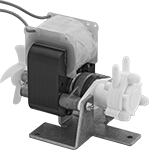
Harsh-Environment Compact Constant-Flow-Rate Gear Pumps for Water and Oil
 |
An aluminum enclosure around the motor provides protection in dusty and dirty environments. Designed to fit into small equipment, these pumps have miniature gears and a fractional horsepower motor for low-flow applications. Pumps are gravity fed and require an elevated liquid source to fully fill the pump before turning on. Do not run dry or use with solids.
Note: If flow control is needed, place valves or reducers on the discharge side; never restrict the inlet of a pump with a valve or reducer.
Intake (NPT) | Discharge (NPT) | Overall | |||||||||||||||||
|---|---|---|---|---|---|---|---|---|---|---|---|---|---|---|---|---|---|---|---|
Max. Flow Rate | Max. ft. of Head, ft. | Max. Pressure, psi | Max. Viscosity, cP | Temp. Range, ° F | Power | Current | Connection | Gender | For Tube ID | Connection | Gender | For Tube ID | Lg. | Wd. | Ht. | Each | |||
12V DC—Without Thermal Overload Protection | |||||||||||||||||||
Hardwire | |||||||||||||||||||
| 0.61 gpm (78 fl oz/min) | 46 | 20 | 800 | 10 to 180 | Fractional | 2.2 amp | Barbed | Male | 3/16" | Barbed | Male | 3/16" | 4" | 1 3/4" | 2 1/2" | 8220K43 | 000000 | ||
24V DC—Without Thermal Overload Protection | |||||||||||||||||||
Hardwire | |||||||||||||||||||
| 0.61 gpm (78 fl oz/min) | 46 | 20 | 800 | 10 to 180 | Fractional | 1.4 amp | Barbed | Male | 3/16" | Barbed | Male | 3/16" | 4" | 1 3/4" | 2 1/2" | 8220K44 | 00000 | ||
Compact Constant-Flow-Rate Gear Pumps for Water and Oil
 |
Designed to fit into small equipment, these pumps have miniature gears and a fractional horsepower motor for low-flow applications. Pumps are gravity fed and require an elevated liquid source to fully fill the pump before turning on. Do not run dry or use with solids.
Note: If flow control is needed, place valves or reducers on the discharge side; never restrict the inlet of a pump with a valve or reducer
Intake (NPT) | Discharge (NPT) | Overall | |||||||||||||||||
|---|---|---|---|---|---|---|---|---|---|---|---|---|---|---|---|---|---|---|---|
Max. Flow Rate | Max. ft. of Head, ft. | Max. Pressure, psi | Max. Viscosity, cP | Temp. Range, ° F | Power | Current | Connection | Gender | For Tube ID | Connection | Gender | For Tube ID | Lg. | Wd. | Ht. | Each | |||
120V AC, Single Phase—With Thermal Overload Protection | |||||||||||||||||||
Hardwire | |||||||||||||||||||
| 0.43 gpm (55 fl oz/min) | 28 | 20 | 800 | 10 to 180 | Fractional | 1.5 amp | Barbed | Male | 3/16" | Barbed | Male | 3/16" | 4 3/8" | 3" | 3 3/4" | 8220K41 | 0000000 | ||
240V AC, Single Phase—With Thermal Overload Protection | |||||||||||||||||||
Hardwire | |||||||||||||||||||
| 0.43 gpm (55 fl oz/min) | 28 | 20 | 800 | 10 to 180 | Fractional | 1.5 amp | Barbed | Male | 3/16" | Barbed | Male | 3/16" | 4 3/8" | 3" | 3 3/4" | 8220K42 | 000000 | ||
Hydraulic Power Units
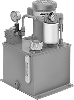 |
Create and supply hydraulic pressure. Choose a unit with a tank capacity about three times greater than your requirement to allow for heat dissipation. An inlet filter protects the pump from contamination.
All units include an additional NPTF threaded inlet port. NPTF (Dryseal) threads are compatible with NPT threads. UN/UNF (SAE Straight) thread connections have straight threads and are also known as O-ring Boss fittings.
Overall | Inlet Connection — UN/UNF (SAE Straight) | Inlet Connection — NPTF | Outlet Connection — UN/UNF (SAE Straight) | ||||||||||||||
|---|---|---|---|---|---|---|---|---|---|---|---|---|---|---|---|---|---|
Max. Flow Rate, gpm | Max. Pressure, psi | Power, hp | Cap., gal. | Lg. | Wd. | Ht. | Thread Size | Dash Size | Pipe Size | Dash Size | Thread Size | Dash Size | Full Load Current @ Voltage | Each | |||
240V AC/460V AC, Three Phase | |||||||||||||||||
| 0.9 | 1,600 | 1 | 5 | 13" | 15" | 20 1/2" | 7/8"-14 | 10 | 1/2 | 08 | 7/8"-14 | 10 | 1.5 amp @ 460V AC | 62915K31 | 000000000 | ||
| 1.3 | 2,300 | 2 | 5 | 13" | 15" | 24 1/2" | 7/8"-14 | 10 | 1/2 | 08 | 7/8"-14 | 10 | 2.8 amp @ 460V AC | 62915K32 | 00000000 | ||
| 2.7 | 1,750 | 3 | 10 | 17 3/8" | 19" | 32 1/2" | 1 1/16"-12 | 12 | 3/4 | 12 | 1 1/16"-12 | 12 | 4.4 amp @ 460V AC | 62915K33 | 00000000 | ||
| 3.6 | 2,050 | 5 | 10 | 17 3/4" | 19" | 29 3/4" | 1 1/16"-12 | 12 | 3/4 | 12 | 1 1/16"-12 | 12 | 6.8 amp @ 460V AC | 62915K44 | 00000000 | ||
| 6.3 | 1,800 | 7 1/2 | 20 | 21 3/8" | 22 1/2" | 37 3/8" | 1 1/16"-12 | 12 | 3/4 | 12 | 1 1/16"-12 | 12 | 9.5 amp @ 460V AC | 62915K36 | 00000000 | ||
| 8.6 | 1,700 | 10 | 30 | 21 3/8" | 22 1/2" | 42 1/4" | 1 1/16"-12 | 12 | 3/4 | 12 | 1 1/16"-12 | 12 | 12 amp @ 460V AC | 62915K47 | 00000000 | ||
| 10.4 | 2,100 | 15 | 30 | 23 3/8" | 22 1/2" | 44 1/8" | 1 1/16"-12 | 12 | 3/4 | 12 | 1 1/16"-12 | 12 | 18.1 amp @ 460V AC | 62915K48 | 000000000 | ||
Self-Priming Circulation Pumps without Motor for Oil
 |
Use these pumps to move lubricating oil such as hydraulic and motor oil. Also known as flexible impeller pumps, they create a suction force that can draw liquid upward to fill the pump chamber when your liquid source is below the pump. The impeller resists clogging and wear. Select a spark-free air motor for hazardous environments or attach an electric motor with a speed reducer or a belt pulley to alter the pump speed.
Repair kits (sold separately) include components such as impellers, O-rings, and seal lips.
Note: Pumps must be filled with liquid before use. They need a constant flow of liquid and cannot run dry.
Shaft | Overall | ||||||||||||||||
|---|---|---|---|---|---|---|---|---|---|---|---|---|---|---|---|---|---|
Max. Flow Rate, gpm | Max. ft. of Head, ft. | Max. Pressure, psi | Max. Viscosity | Temp. Range, ° F | Req. Power, hp | Intake Connection Type | Discharge Connection Type | Dia. | Lg. | Ctr.-to-Base Lg. | Ht. | Lg. | Wd. | Each | |||
For 500 rpm to 2,100 rpm Motor Speed | |||||||||||||||||
| 11.5 | 50 | 21 | Not Rated | 50 to 180 | 1/3 | 1/2 Female NPT | 1/2 Female NPT | 5/8" | 1 1/8" | 1 15/16" | 3 13/16" | 4 1/2" | 4 1/8" | 4281K24 | 0000000 | ||
| 25 | 50 | 26 | Not Rated | 50 to 180 | 3/4 | 1 Female NPT | 1 Female NPT | 5/8" | 2 1/4" | 1 7/8" | 3 9/16" | 6 3/8" | 4 3/4" | 4281K26 | 000000 | ||
Air-Powered Constant-Flow-Rate Piston Pumps
 |
Commonly called piston pumps, these are often used in high-pressure applications, such as hydrostatic testing of pipelines, tanks, and valves. Flow and outlet liquid pressure can be controlled by varying the air pressure. To calculate discharge liquid pressure, multiply the air pressure by the ratio shown in the table. Pumps are self-priming, which means they create a suction force to draw liquid upward to fill the pump chamber.
Note: Pumps must be filled with liquid before use. They need a constant flow of liquid and cannot run dry.
Flow Rate, gpm | Air Pressure, psi | Overall | |||||||||||||||
|---|---|---|---|---|---|---|---|---|---|---|---|---|---|---|---|---|---|
@ 0 psi | @ 3,000 psi | Max. ft. of Head, ft. | Max. Discharge Pressure, psi | Max. Viscosity, cP | Min. | Max. | Air Consumption, scfm | Air Connection (NPT) | Intake Pipe Connection (NPT) | Discharge Pipe Connection (NPT) | Lg. | Wd. | Ht. | Each | |||
86:1 Discharge Liquid to Inlet Air Pressure Ratio | |||||||||||||||||
| 0.19 | 0.17 | 28,764 | 12,470 | 100 | 15 | 145 | 20 | 1/4 Female | 3/8 Female | 1/4 Female | 4 5/8" | 4" | 9" | 6770K43 | 000000000 | ||
28:1 Discharge Liquid to Inlet Air Pressure Ratio | |||||||||||||||||
| 0.58 | 0.13 | 9,365 | 4,060 | 100 | 15 | 145 | 20 | 1/4 Female | 3/8 Female | 1/4 Female | 4 5/8" | 4" | 9" | 6770K41 | 00000000 | ||
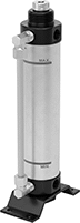
Slim-Shaft Hydraulic Power Units
 | 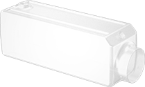 |
Replacement Hydraulic Tanks |
Slim enough to mount directly on machinery or tuck into tight spaces, these hydraulic power units create and supply pressure where standard models won't fit. Choose a unit with a tank capacity about three times greater than your requirement to allow for heat dissipation. Replacement hydraulic tanks restore a worn or damaged tank without replacing the entire power unit, saving cost and downtime.
Hydraulic Power Units | Replacement Hydraulic Tanks | ||||||||||||||||
|---|---|---|---|---|---|---|---|---|---|---|---|---|---|---|---|---|---|
Overall | Inlet Connection — NPT | Outlet Connection — NPT | |||||||||||||||
Max. Flow Rate, gpm | Max. Pressure, psi | Power, hp | Cap., gal. | Lg. | Wd. | Ht. | Pipe Size | Dash Size | Pipe Size | Dash Size | Full Load Current @ Voltage | Each | Each | ||||
120V AC/240V AC, Single Phase | |||||||||||||||||
| 1 | 2,500 | 2 | 2.3 | 36 1/8" | 8 1/8" | 8 5/8" | 1/4 | 04 | 3/8 | 06 | 10 amp @ 240V AC | 3973K41 | 000000000 | 3973K415 | 0000000 | ||
| 1.5 | 2,500 | 2 | 2.3 | 34 7/8" | 8 1/8" | 8 5/8" | 1/4 | 04 | 3/8 | 06 | 10 amp @ 240V AC | 3973K42 | 00000000 | 3973K415 | 000000 | ||
Air to Hydraulic Power Units
 |
Power a hydraulic cylinder from your air system to avoid the setup, cost, and mess of hydraulic fluid. These converters give you more consistent power than using air power for an air cylinder. However, because air works at a lower pressure than hydraulic fluid, your hydraulic cylinder won’t move loads at its full force. Attach these converters to an air line with a speed controller and solenoid (not included).
Note: These converters are not for use near fire.
Oil Displacement, mm | Overall, mm | Inlet Connection—BSPT | Outlet Connection—BSPT | Drain Connection—BSPT | Mounting Holes | |||||||||||||||
|---|---|---|---|---|---|---|---|---|---|---|---|---|---|---|---|---|---|---|---|---|
Max. | Increments | For Max. Hydraulic Cylinder Stroke Lg., mm | Max. Flow Rate, gpm | Max. Pressure, psi | Cap., gal. | Wd. | Ht. | Pipe Size | Dash Size | Pipe Size | Dash Size | Pipe Size | Dash Size | No. of | Dia., mm | Features | Each | |||
For 40 mm Bore Dia. | ||||||||||||||||||||
| 50 | 50 | 60 | 3.3 | 100 | 0.02 | 107 | 213 | 1/4 | 06 | 1/4 | 06 | — | — | 4 | 7 | Drain Plug | 6476N11 | 000000 | ||
| 100 | 50 | 120 | 3.3 | 100 | 0.03 | 107 | 263 | 1/4 | 06 | 1/4 | 06 | — | — | 4 | 7 | Drain Plug | 6476N12 | 00000 | ||
| 150 | 50 | 180 | 3.3 | 100 | 0.05 | 107 | 313 | 1/4 | 06 | 1/4 | 06 | — | — | 4 | 7 | Drain Plug | 6476N13 | 00000 | ||
| 200 | 50 | 250 | 3.3 | 100 | 0.07 | 107 | 363 | 1/4 | 06 | 1/4 | 06 | — | — | 4 | 7 | Drain Plug | 6476N14 | 00000 | ||
For 63 mm Bore Dia. | ||||||||||||||||||||
| 50 | 50 | 150 | 7.9 | 100 | 0.04 | 104 | 228 | 3/8 | 06 | 3/4 | 12 | 1/4 | 06 | 4 | 11 | Drain Plug | 6476N15 | 00000 | ||
| 100 | 50 | 300 | 7.9 | 100 | 0.08 | 104 | 278 | 3/8 | 06 | 3/4 | 12 | 1/4 | 06 | 4 | 11 | Drain Plug | 6476N16 | 000000 | ||
| 200 | 50 | 600 | 7.9 | 100 | 0.16 | 104 | 378 | 3/8 | 06 | 3/4 | 12 | 1/4 | 06 | 4 | 11 | Drain Plug | 6476N17 | 000000 | ||
| 300 | 50 | 890 | 7.9 | 100 | 0.24 | 104 | 503 | 3/8 | 06 | 3/4 | 12 | 1/4 | 06 | 4 | 11 | Drain Plug | 6476N18 | 000000 | ||
