


Filter by
Width
Mounting Hole Center-to-Center
Motor Frame Size
Actuation Type
Export Control Classification Number (ECCN)
DFARS Specialty Metals
Hydraulic Cylinder Mounting Pattern
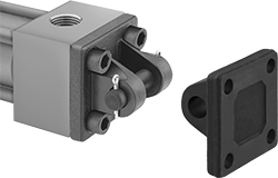
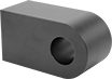
Hydraulic Cylinder Clevis Brackets
 |
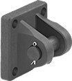 |  |
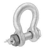
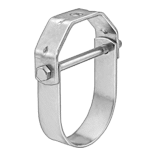
Bracket with Clevis Pin and Cotter Pins | Bracket |
 |
Mounting Hole | |||||||||||||||||||||||||||||||||||||||||||||||||||||||||||||||||||||||||||||||||||||||||||||||||||
|---|---|---|---|---|---|---|---|---|---|---|---|---|---|---|---|---|---|---|---|---|---|---|---|---|---|---|---|---|---|---|---|---|---|---|---|---|---|---|---|---|---|---|---|---|---|---|---|---|---|---|---|---|---|---|---|---|---|---|---|---|---|---|---|---|---|---|---|---|---|---|---|---|---|---|---|---|---|---|---|---|---|---|---|---|---|---|---|---|---|---|---|---|---|---|---|---|---|---|---|
For Bore Dia. | Pin Dia. | Wd. | Ht. | Dp. | Jaw Opening Wd. | Base Plate Thk. | Dia. | Ctr.-to-Ctr. | Mounting Fasteners Included | For Hydraulic Cylinder Mounting Pattern | Includes | Each | |||||||||||||||||||||||||||||||||||||||||||||||||||||||||||||||||||||||||||||||||||||||
Steel | |||||||||||||||||||||||||||||||||||||||||||||||||||||||||||||||||||||||||||||||||||||||||||||||||||
| 1 1/2" | 1/2" | 2 1/2" | 2 1/2" | 1 5/8" | 3/4" | 3/8" | 3/8" | 1 5/8" | Yes | NFPA/JIC Heavy Duty | Clevis Pin, Two Cotter Pins | 62205K18 | 0000000 | ||||||||||||||||||||||||||||||||||||||||||||||||||||||||||||||||||||||||||||||||||||||
| 2" | 3/4" | 3" | 3" | 2 5/8" | 1 1/4" | 5/8" | 9/16" | 2 1/16" | Yes | NFPA/JIC Heavy Duty | Clevis Pin, Two Cotter Pins | 62205K28 | 000000 | ||||||||||||||||||||||||||||||||||||||||||||||||||||||||||||||||||||||||||||||||||||||
| 2 1/2" | 3/4" | 3 1/2" | 3 1/2" | 2 5/8" | 1 1/4" | 5/8" | 9/16" | 2 9/16" | Yes | NFPA/JIC Heavy Duty | Clevis Pin, Two Cotter Pins | 62205K38 | 000000 | ||||||||||||||||||||||||||||||||||||||||||||||||||||||||||||||||||||||||||||||||||||||
| 3 1/4" | 1" | 4 1/2" | 4 1/2" | 3 1/4" | 1 1/2" | 3/4" | 5/8" | 3 1/4" | Yes | NFPA/JIC Heavy Duty | Clevis Pin, Two Cotter Pins | 62205K48 | 000000 | ||||||||||||||||||||||||||||||||||||||||||||||||||||||||||||||||||||||||||||||||||||||
| 4" | 1 3/8" | 5" | 5" | 4 3/8" | 2 1/16" | 7/8" | 5/8" | 3 13/16" | Yes | NFPA/JIC Heavy Duty | Clevis Pin, Two Cotter Pins | 62205K58 | 000000 | ||||||||||||||||||||||||||||||||||||||||||||||||||||||||||||||||||||||||||||||||||||||
Stainless Steel | |||||||||||||||||||||||||||||||||||||||||||||||||||||||||||||||||||||||||||||||||||||||||||||||||||
| — | 1/2" | 3 1/2" | 3 1/2" | 2" | 3/4" | 1/2" | 3/8" | 2 1/2" | No | NFPA/JIC Heavy Duty | — | 6020N11 | 000000 | ||||||||||||||||||||||||||||||||||||||||||||||||||||||||||||||||||||||||||||||||||||||
| — | 3/4" | 5" | 5" | 2 5/8" | 1 1/4" | 5/8" | 1/2" | 3 13/16" | No | NFPA/JIC Heavy Duty | — | 6020N12 | 00000000 | ||||||||||||||||||||||||||||||||||||||||||||||||||||||||||||||||||||||||||||||||||||||
| — | 1" | 6 1/2" | 6 1/2" | 3 1/4" | 1 9/16" | 3/4" | 5/8" | 4 15/16" | No | NFPA/JIC Heavy Duty | — | 6020N13 | 00000000 | ||||||||||||||||||||||||||||||||||||||||||||||||||||||||||||||||||||||||||||||||||||||
| — | 1 3/8" | 7 1/2" | 7 1/2" | 4 5/8" | 2 1/16" | 7/8" | 5/8" | 5 11/16" | No | NFPA/JIC Heavy Duty | — | 6020N14 | 00000000 | ||||||||||||||||||||||||||||||||||||||||||||||||||||||||||||||||||||||||||||||||||||||
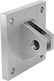
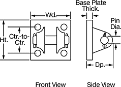
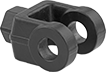
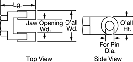
Hydraulic Cylinder Pivot Brackets
 | 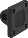 | 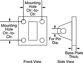 |
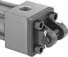
Pivot Bracket |
Mounting Hole | |||||||||||||||||||||||||||||||||||||||||||||||||||||||||||||||||||||||||||||||||||||||||||||||||||
|---|---|---|---|---|---|---|---|---|---|---|---|---|---|---|---|---|---|---|---|---|---|---|---|---|---|---|---|---|---|---|---|---|---|---|---|---|---|---|---|---|---|---|---|---|---|---|---|---|---|---|---|---|---|---|---|---|---|---|---|---|---|---|---|---|---|---|---|---|---|---|---|---|---|---|---|---|---|---|---|---|---|---|---|---|---|---|---|---|---|---|---|---|---|---|---|---|---|---|---|
For Bore Dia. | For Pin Dia. | Wd. | Ht. | Dp. | Base Plate Thk. | Dia. | Ctr.-to-Ctr. | Mounting Fasteners Included | For Hydraulic Cylinder Mounting Pattern | Each | |||||||||||||||||||||||||||||||||||||||||||||||||||||||||||||||||||||||||||||||||||||||||
Steel | |||||||||||||||||||||||||||||||||||||||||||||||||||||||||||||||||||||||||||||||||||||||||||||||||||
| 1 1/2" | 1/2" | 2 1/2" | 2 1/2" | 1 5/8" | 3/8" | 13/32" | 1 5/8" | No | NFPA Light Duty, NFPA/JIC Heavy Duty | 62205K14 | 000000 | ||||||||||||||||||||||||||||||||||||||||||||||||||||||||||||||||||||||||||||||||||||||||
| 2", 2 1/2" | 3/4" | 3 1/2" | 3 1/2" | 2 5/8" | 5/8" | 17/32" | 2 9/16" | No | NFPA Light Duty, NFPA/JIC Heavy Duty | 62205K24 | 00000 | ||||||||||||||||||||||||||||||||||||||||||||||||||||||||||||||||||||||||||||||||||||||||
| 3 1/4" | 1" | 4 1/2" | 4 1/2" | 3 1/4" | 3/4" | 21/32" | 3 1/4" | No | NFPA Light Duty, NFPA/JIC Heavy Duty | 62205K34 | 000000 | ||||||||||||||||||||||||||||||||||||||||||||||||||||||||||||||||||||||||||||||||||||||||
Iron | |||||||||||||||||||||||||||||||||||||||||||||||||||||||||||||||||||||||||||||||||||||||||||||||||||
| 4" | 1 3/8" | 5" | 5" | 4 3/8" | 7/8" | 21/32" | 3 13/16" | No | NFPA Light Duty, NFPA/JIC Heavy Duty | 62205K44 | 000000 | ||||||||||||||||||||||||||||||||||||||||||||||||||||||||||||||||||||||||||||||||||||||||
Stainless Steel | |||||||||||||||||||||||||||||||||||||||||||||||||||||||||||||||||||||||||||||||||||||||||||||||||||
| — | 1/2" | 2 1/2" | 2 1/2" | 1 5/8" | 3/8" | 13/32" | 1 5/8" | No | NFPA Light Duty, NFPA/JIC Heavy Duty | 5765N11 | 000000 | ||||||||||||||||||||||||||||||||||||||||||||||||||||||||||||||||||||||||||||||||||||||||
| — | 3/4" | 3 1/2" | 3 1/2" | 2 5/8" | 5/8" | 17/32" | 2 9/16" | No | NFPA Light Duty, NFPA/JIC Heavy Duty | 5765N12 | 000000 | ||||||||||||||||||||||||||||||||||||||||||||||||||||||||||||||||||||||||||||||||||||||||
| — | 1" | 4 1/2" | 4 1/2" | 3 3/8" | 7/8" | 21/32" | 3 1/4" | No | NFPA Light Duty, NFPA/JIC Heavy Duty | 5765N13 | 000000 | ||||||||||||||||||||||||||||||||||||||||||||||||||||||||||||||||||||||||||||||||||||||||
| — | 1 3/8" | 5" | 5" | 4 3/8" | 7/8" | 21/32" | 3 13/16" | No | NFPA Light Duty, NFPA/JIC Heavy Duty | 5765N14 | 00000000 | ||||||||||||||||||||||||||||||||||||||||||||||||||||||||||||||||||||||||||||||||||||||||
Hydraulic Pump-to-Motor Mount Adapters
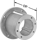 |
Mate a NEMA C-face motor to the mounting flange of a hydraulic pump. Mount adapters reduce noise and protect the shaft and coupling connection between the motor and the pump.
For SAE Pump Flange Size | For Motor Frame Size | Dp. | Mounting Flange Angle | Material | Each | ||
|---|---|---|---|---|---|---|---|
| AA | NEMA 56C, NEMA 143TC, NEMA 145TC, NEMA 182UC, NEMA 184UC | 3.53" | — | Aluminum | 4851N12 | 000000 | |
| AA | NEMA 56C, NEMA 143TC, NEMA 145TC | 4.25" | — | Aluminum | 62905K42 | 00000 | |
| AA | NEMA 182TC, NEMA 184TC, NEMA 213TC, NEMA 213UC, NEMA 215TC, NEMA 215UC, NEMA 254TC, NEMA 254UC, NEMA 256TC, NEMA 256UC | 5" | — | Aluminum | 4851N16 | 000000 | |
| AA | NEMA 182TC, NEMA 184TC, NEMA 213TC, NEMA 213UC, NEMA 215TC, NEMA 215UC, NEMA 254TC, NEMA 254UC, NEMA 256TC, NEMA 256UC | 5.88" | — | Aluminum | 4851N17 | 000000 | |
| A | NEMA 56C, NEMA 143TC, NEMA 145TC, NEMA 182UC, NEMA 184UC | 3.53" | — | Aluminum | 4851N13 | 00000 | |
| A | NEMA 56C, NEMA 143TC, NEMA 145TC | 4.25" | — | Aluminum | 62905K43 | 00000 | |
| A | NEMA 56C, NEMA 143TC, NEMA 145TC, NEMA 182UC, NEMA 184UC | 5" | — | Aluminum | 4851N14 | 000000 | |
| A | NEMA 182TC, NEMA 184TC, NEMA 213TC, NEMA 215TC, NEMA 254TC, NEMA 256TC | 5" | — | Aluminum | 62905K44 | 00000 | |
| A | NEMA 182TC, NEMA 184TC, NEMA 213TC, NEMA 215TC, NEMA 254TC, NEMA 256TC | 5.81" | — | Aluminum | 62905K45 | 00000 | |
| A | NEMA 182TC, NEMA 184TC, NEMA 213TC, NEMA 215TC, NEMA 254TC, NEMA 256TC | 6.81" | — | Aluminum | 62905K47 | 00000 | |
| A | NEMA 284TC, NEMA 284TSC, NEMA 284UC, NEMA 286TC, NEMA 286TSC, NEMA 286USC | 7.19" | — | Aluminum | 4851N23 | 000000 | |
| B | NEMA 56C, NEMA 143TC, NEMA 145TC, NEMA 182UC, NEMA 184UC | 4.25" | — | Aluminum | 4851N15 | 000000 | |
| B | NEMA 182TC, NEMA 184TC, NEMA 213TC, NEMA 213UC, NEMA 215TC, NEMA 215UC, NEMA 254TC, NEMA 254UC, NEMA 256TC, NEMA 256UC | 5" | — | Aluminum | 4851N18 | 00000 | |
| B | NEMA 182TC, NEMA 184TC, NEMA 213TC, NEMA 215TC, NEMA 254TC, NEMA 256TC | 5.81" | — | Aluminum | 62905K51 | 00000 | |
| B | NEMA 182TC, NEMA 184TC, NEMA 213TC, NEMA 213UC, NEMA 215TC, NEMA 215UC, NEMA 254TC, NEMA 254UC, NEMA 256TC, NEMA 256UC | 6.38" | 45° | Aluminum | 4851N21 | 000000 | |
| B | NEMA 182TC, NEMA 184TC, NEMA 213TC, NEMA 215TC, NEMA 254TC, NEMA 256TC | 6.81" | — | Aluminum | 62905K48 | 00000 | |
| B | NEMA 284TC, NEMA 284TSC, NEMA 284UC, NEMA 286TC, NEMA 286TSC, NEMA 286USC | 7.88" | — | Aluminum | 4851N24 | 000000 | |
| C | NEMA 182TC, NEMA 184TC, NEMA 213TC, NEMA 213UC, NEMA 215TC, NEMA 215UC, NEMA 254TC, NEMA 254UC, NEMA 256TC, NEMA 256UC | 6.38" | — | Aluminum | 4851N19 | 000000 | |
| C | NEMA 182TC, NEMA 184TC, NEMA 213TC, NEMA 213UC, NEMA 215TC, NEMA 215UC, NEMA 254TC, NEMA 254UC, NEMA 256TC, NEMA 256UC | 6.38" | 45° | Aluminum | 4851N22 | 000000 | |
| 4F17 | NEMA 56C, NEMA 143TC, NEMA 145TC, NEMA 182UC, NEMA 184UC | 3.53" | — | Aluminum | 4851N11 | 00000 | |
| 4F17 | NEMA 56C, NEMA 143TC, NEMA 145TC | 4.25" | — | Aluminum | 62905K41 | 00000 |
Hydraulic Cylinder Flat-Shoulder Rod Ends
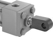 |  | 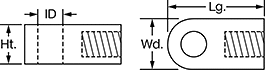 |
Rod End Installed on Hydraulic Cylinder |
For Bore Dia. | ID | Thread Size | Lg. | Wd. | Ht. | Gender | For Hydraulic Cylinder Mounting Pattern | Each | |||||||||||||||||||||||||||||||||||||||||||||||||||||||||||||||||||||||||||||||||||||||||||
|---|---|---|---|---|---|---|---|---|---|---|---|---|---|---|---|---|---|---|---|---|---|---|---|---|---|---|---|---|---|---|---|---|---|---|---|---|---|---|---|---|---|---|---|---|---|---|---|---|---|---|---|---|---|---|---|---|---|---|---|---|---|---|---|---|---|---|---|---|---|---|---|---|---|---|---|---|---|---|---|---|---|---|---|---|---|---|---|---|---|---|---|---|---|---|---|---|---|---|---|
Steel | |||||||||||||||||||||||||||||||||||||||||||||||||||||||||||||||||||||||||||||||||||||||||||||||||||
| 7/16" | 1/2" | 7/16"-20 | 2" | 1" | 3/4" | Female | NFPA Light Duty, NFPA/JIC Heavy Duty | 6466N11 | 000000 | ||||||||||||||||||||||||||||||||||||||||||||||||||||||||||||||||||||||||||||||||||||||||||
| 3/4" | 3/4" | 3/4"-16 | 2 13/16" | 1 1/2" | 1 1/4" | Female | NFPA Light Duty, NFPA/JIC Heavy Duty | 6466N12 | 00000 | ||||||||||||||||||||||||||||||||||||||||||||||||||||||||||||||||||||||||||||||||||||||||||
| 1" | 1" | 1"-14 | 3 13/16" | 2" | 1 1/2" | Female | NFPA Light Duty, NFPA/JIC Heavy Duty | 6466N13 | 00000 | ||||||||||||||||||||||||||||||||||||||||||||||||||||||||||||||||||||||||||||||||||||||||||
| 1 1/4" | 1 3/8" | 1 1/4"-12 | 4 13/16" | 2 3/4" | 2" | Female | NFPA Light Duty, NFPA/JIC Heavy Duty | 6466N14 | 00000 | ||||||||||||||||||||||||||||||||||||||||||||||||||||||||||||||||||||||||||||||||||||||||||
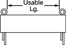
Hydraulic Cylinder Clevis Pins
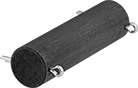 |  |
Secure parts onto hydraulic cylinders. Use these pins with clevis rod ends and pivot brackets (sold separately).
17-4 PH Stainless Steel—Stainless steel pins are more corrosion resistant than steel pins in wet environments.
For Bore Dia. | Dia. | Usable Lg. | Lg. | Through-Hole Dia. | For Hydraulic Cylinder Mounting Pattern | Includes | Each | ||||||||||||||||||||||||||||||||||||||||||||||||||||||||||||||||||||||||||||||||||||||||||||
|---|---|---|---|---|---|---|---|---|---|---|---|---|---|---|---|---|---|---|---|---|---|---|---|---|---|---|---|---|---|---|---|---|---|---|---|---|---|---|---|---|---|---|---|---|---|---|---|---|---|---|---|---|---|---|---|---|---|---|---|---|---|---|---|---|---|---|---|---|---|---|---|---|---|---|---|---|---|---|---|---|---|---|---|---|---|---|---|---|---|---|---|---|---|---|---|---|---|---|---|
1144 Carbon Steel | |||||||||||||||||||||||||||||||||||||||||||||||||||||||||||||||||||||||||||||||||||||||||||||||||||
| 1 1/2" | 1/2" | 1 15/16" | 2 9/32" | 0.106" | NFPA Light Duty, NFPA/JIC Heavy Duty | Two Cotter Pins | 62205K12 | 000000 | |||||||||||||||||||||||||||||||||||||||||||||||||||||||||||||||||||||||||||||||||||||||||||
| 2", 2 1/2" | 3/4" | 2 23/32" | 3 3/32" | 0.14" | NFPA Light Duty, NFPA/JIC Heavy Duty | Two Cotter Pins | 62205K22 | 00000 | |||||||||||||||||||||||||||||||||||||||||||||||||||||||||||||||||||||||||||||||||||||||||||
| 3 1/4" | 1" | 3 7/32" | 3 19/32" | 0.14" | NFPA Light Duty, NFPA/JIC Heavy Duty | Two Cotter Pins | 62205K32 | 00000 | |||||||||||||||||||||||||||||||||||||||||||||||||||||||||||||||||||||||||||||||||||||||||||
| 4" | 1 3/8" | 4 1/4" | 4 21/32" | 0.173" | NFPA Light Duty, NFPA/JIC Heavy Duty | Two Cotter Pins | 62205K42 | 00000 | |||||||||||||||||||||||||||||||||||||||||||||||||||||||||||||||||||||||||||||||||||||||||||
17-4 PH Stainless Steel | |||||||||||||||||||||||||||||||||||||||||||||||||||||||||||||||||||||||||||||||||||||||||||||||||||
| — | 1/2" | 1 7/8" | 2 1/8" | — | NFPA Light Duty, NFPA/JIC Heavy Duty | Two Retaining Rings | 6033N11 | 000000 | |||||||||||||||||||||||||||||||||||||||||||||||||||||||||||||||||||||||||||||||||||||||||||
| — | 3/4" | 2 5/8" | 2 7/8" | — | NFPA Light Duty, NFPA/JIC Heavy Duty | Two Retaining Rings | 6033N12 | 000000 | |||||||||||||||||||||||||||||||||||||||||||||||||||||||||||||||||||||||||||||||||||||||||||
| — | 1" | 3 1/8" | 3 3/8" | — | NFPA Light Duty, NFPA/JIC Heavy Duty | Two Retaining Rings | 6033N13 | 000000 | |||||||||||||||||||||||||||||||||||||||||||||||||||||||||||||||||||||||||||||||||||||||||||
| — | 1 3/8" | 4 1/8" | 4 3/8" | — | NFPA Light Duty, NFPA/JIC Heavy Duty | Two Retaining Rings | 6033N14 | 000000 | |||||||||||||||||||||||||||||||||||||||||||||||||||||||||||||||||||||||||||||||||||||||||||
Mounts for Round Body Hydraulic Cylinders
 |
Rod End Nut for Universal Mount Air Cylinders
For Bore Size, mm | Overall Dia., mm | ID, mm | Thread Size | Material | Gender | Each | ||
|---|---|---|---|---|---|---|---|---|
| 32 | 24 | 12 | M14 × 1.5 mm | Nickel-Plated Steel | Female | 6024N45 | 000000 |
Hydraulic Cylinder Front/Rear Flanges
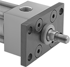 |  |  |
Front/Rear Flange |
Inside Mounting Hole | Outside Mounting Hole | ||||||||||||||||||||||||||||||||||||||||||||||||||||||||||||||||||||||||||||||||||||||||||||||||||
|---|---|---|---|---|---|---|---|---|---|---|---|---|---|---|---|---|---|---|---|---|---|---|---|---|---|---|---|---|---|---|---|---|---|---|---|---|---|---|---|---|---|---|---|---|---|---|---|---|---|---|---|---|---|---|---|---|---|---|---|---|---|---|---|---|---|---|---|---|---|---|---|---|---|---|---|---|---|---|---|---|---|---|---|---|---|---|---|---|---|---|---|---|---|---|---|---|---|---|---|
For Bore Dia. | Wd. | Ht. | Thk. | For Rod Gland Dia. | Dia. | Ctr.-to-Ctr. | Dia. | Ctr.-to-Ctr. | Mounting Fasteners Included | For Hydraulic Cylinder Mounting Pattern | Each | ||||||||||||||||||||||||||||||||||||||||||||||||||||||||||||||||||||||||||||||||||||||||
Steel | |||||||||||||||||||||||||||||||||||||||||||||||||||||||||||||||||||||||||||||||||||||||||||||||||||
| 1 1/2" | 4 1/4" | 2 1/2" | 3/8" | 7/8" | 3/8" | 1 5/8" | 7/16" | 3 7/16" | Yes | NFPA/JIC Heavy Duty | 62205K145 | 0000000 | |||||||||||||||||||||||||||||||||||||||||||||||||||||||||||||||||||||||||||||||||||||||
| 2" | 5 1/8" | 3" | 5/8" | 1 3/8" | 1/2" | 2 1/16" | 9/16" | 4 1/8" | Yes | NFPA/JIC Heavy Duty | 62205K571 | 000000 | |||||||||||||||||||||||||||||||||||||||||||||||||||||||||||||||||||||||||||||||||||||||
| 2 1/2" | 5 5/8" | 3 1/2" | 5/8" | 1 3/8" | 1/2" | 2 9/16" | 9/16" | 4 5/8" | Yes | NFPA/JIC Heavy Duty | 62205K136 | 000000 | |||||||||||||||||||||||||||||||||||||||||||||||||||||||||||||||||||||||||||||||||||||||
| 3 1/4" | 7 1/8" | 4 1/2" | 3/4" | 1 15/16" | 5/8" | 3 1/4" | 11/16" | 5 7/8" | Yes | NFPA/JIC Heavy Duty | 62205K146 | 000000 | |||||||||||||||||||||||||||||||||||||||||||||||||||||||||||||||||||||||||||||||||||||||
| 4" | 7 5/8" | 5" | 7/8" | 2 7/16" | 5/8" | 3 13/16" | 11/16" | 6 3/8" | Yes | NFPA/JIC Heavy Duty | 62205K156 | 000000 | |||||||||||||||||||||||||||||||||||||||||||||||||||||||||||||||||||||||||||||||||||||||
Hydraulic Cylinder Clevis Rod Ends
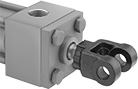 |  |  |
Clevis Rod Ends |
Overall | Shank | ||||||||||||||||||||||||||||||||||||||||||||||||||||||||||||||||||||||||||||||||||||||||||||||||||
|---|---|---|---|---|---|---|---|---|---|---|---|---|---|---|---|---|---|---|---|---|---|---|---|---|---|---|---|---|---|---|---|---|---|---|---|---|---|---|---|---|---|---|---|---|---|---|---|---|---|---|---|---|---|---|---|---|---|---|---|---|---|---|---|---|---|---|---|---|---|---|---|---|---|---|---|---|---|---|---|---|---|---|---|---|---|---|---|---|---|---|---|---|---|---|---|---|---|---|---|
For Bore Dia. | For Pin Dia. | Jaw Opening Wd. | Shank Ctr. Lg. | Wd. | Lg. | Ht. | Thread Size | Gender | Threading | For Hydraulic Cylinder Mounting Pattern | Each | ||||||||||||||||||||||||||||||||||||||||||||||||||||||||||||||||||||||||||||||||||||||||
Steel | |||||||||||||||||||||||||||||||||||||||||||||||||||||||||||||||||||||||||||||||||||||||||||||||||||
| 1 1/2" | 1/2" | 3/4" | 1 1/2" | 1 3/4" | 2" | 1" | 7/16"-20 | Female | Fully Threaded | NFPA Light Duty, NFPA/JIC Heavy Duty | 62205K19 | 000000 | |||||||||||||||||||||||||||||||||||||||||||||||||||||||||||||||||||||||||||||||||||||||
| 2", 2 1/2" | 3/4" | 1 1/4" | 2 3/8" | 2 1/2" | 3 1/8" | 1 1/2" | 3/4"-16 | Female | Fully Threaded | NFPA Light Duty, NFPA/JIC Heavy Duty | 62205K29 | 00000 | |||||||||||||||||||||||||||||||||||||||||||||||||||||||||||||||||||||||||||||||||||||||
| 3 1/4" | 1" | 1 1/2" | 3 1/8" | 3" | 4 1/8" | 2" | 1"-14 | Female | Fully Threaded | NFPA Light Duty, NFPA/JIC Heavy Duty | 62205K39 | 000000 | |||||||||||||||||||||||||||||||||||||||||||||||||||||||||||||||||||||||||||||||||||||||
Iron | |||||||||||||||||||||||||||||||||||||||||||||||||||||||||||||||||||||||||||||||||||||||||||||||||||
| 4" | 1 3/8" | 2 1/16" | 4 1/8" | 4 1/16" | 5 1/2" | 2 3/4" | 1 1/4"-12 | Female | Fully Threaded | NFPA Light Duty, NFPA/JIC Heavy Duty | 62205K49 | 000000 | |||||||||||||||||||||||||||||||||||||||||||||||||||||||||||||||||||||||||||||||||||||||
Stainless Steel | |||||||||||||||||||||||||||||||||||||||||||||||||||||||||||||||||||||||||||||||||||||||||||||||||||
| — | 1/2" | 3/4" | 1 1/2" | 1 3/4" | 2" | 1" | 7/16"-20 | Female | Fully Threaded | NFPA Light Duty, NFPA/JIC Heavy Duty | 6043N11 | 000000 | |||||||||||||||||||||||||||||||||||||||||||||||||||||||||||||||||||||||||||||||||||||||
| — | 3/4" | 1 1/4" | 2 3/8" | 2 1/2" | 3 1/8" | 1 1/2" | 3/4"-16 | Female | Fully Threaded | NFPA Light Duty, NFPA/JIC Heavy Duty | 6043N12 | 000000 | |||||||||||||||||||||||||||||||||||||||||||||||||||||||||||||||||||||||||||||||||||||||
| — | 1" | 1 1/2" | 3 1/8" | 3" | 4 1/8" | 2" | 1"-14 | Female | Fully Threaded | NFPA Light Duty, NFPA/JIC Heavy Duty | 6043N13 | 000000 | |||||||||||||||||||||||||||||||||||||||||||||||||||||||||||||||||||||||||||||||||||||||
| — | 1 3/8" | 2 1/16" | 4 1/8" | 4 1/16" | 5 1/2" | 2 3/4" | 1 1/4"-12 | Female | Fully Threaded | NFPA Light Duty, NFPA/JIC Heavy Duty | 6043N14 | 00000000 | |||||||||||||||||||||||||||||||||||||||||||||||||||||||||||||||||||||||||||||||||||||||
Self-Adjusting Rigid Leveling Mounts with Threaded Stud

Mounting Blocks for Threaded-Body Hydraulic Cylinders

