


Filter by
Thread Size

Threaded Insert Type
For Tap Thread Size
Material


Thread Direction
Thread Type

Helical Insert Type

Export Control Classification Number (ECCN)
DFARS Specialty Metals
Thread Spacing
Sold As
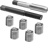
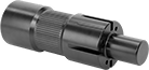
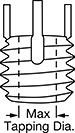
Key-Locking Threaded Inserts for Soft Metal
 |
Add strong threads in soft metal, such as aluminum. The keys on these inserts drive into holes to hold more securely than thread-locking or helical inserts. They prevent slipping and rotating, so they’re stable enough for use in vehicle or aerospace parts that experience heavy vibration. These inserts are comparable to Keensert inserts.
To install, drill and tap a hole in your material. Then, thread the insert onto the installation tool and screw it into the hole. Place the tool over the keys and hit it with a hammer to drive them in.
Standard Wall—Stronger than thin-wall inserts, these are your go-to choice for threading most holes.
Black Phosphate-Coated Steel—These inserts resist occasional moisture.
18-8 Stainless Steel—The choice for wet and outdoor environments, these inserts resist rust and mild chemicals.
Inserts | Installation Tools | Inserts with Installation Tools | |||||||||||||||||||||||||||||||||||||||||||||||||||||||||||||||||||||||||||||||||||||||||||||||||
|---|---|---|---|---|---|---|---|---|---|---|---|---|---|---|---|---|---|---|---|---|---|---|---|---|---|---|---|---|---|---|---|---|---|---|---|---|---|---|---|---|---|---|---|---|---|---|---|---|---|---|---|---|---|---|---|---|---|---|---|---|---|---|---|---|---|---|---|---|---|---|---|---|---|---|---|---|---|---|---|---|---|---|---|---|---|---|---|---|---|---|---|---|---|---|---|---|---|---|---|
Each | |||||||||||||||||||||||||||||||||||||||||||||||||||||||||||||||||||||||||||||||||||||||||||||||||||
Thread Size | For Tap Thread Size | Installed Lg., mm | Drill Bit Size, mm | For Max. Hole Dia., mm | No. of Locking Keys | 1-9 | 10-Up | Each | No. of Inserts Included | Each | |||||||||||||||||||||||||||||||||||||||||||||||||||||||||||||||||||||||||||||||||||||||||
Standard Wall | |||||||||||||||||||||||||||||||||||||||||||||||||||||||||||||||||||||||||||||||||||||||||||||||||||
Black Phosphate-Coated Steel | |||||||||||||||||||||||||||||||||||||||||||||||||||||||||||||||||||||||||||||||||||||||||||||||||||
| M20 x 1.5 mm | M30 x 2 mm | 30 | 28 | 28 | 4 | 90245A205 | 000000 | 000000 | 94010A355 | 000000 | 3 | 90245A331 | 000000 | ||||||||||||||||||||||||||||||||||||||||||||||||||||||||||||||||||||||||||||||||||||||
| M20 x 2.5 mm | M30 x 2 mm | 30 | 28 | 28 | 4 | 90245A201 | 00000 | 00000 | 94010A355 | 00000 | 3 | 90245A326 | 00000 | ||||||||||||||||||||||||||||||||||||||||||||||||||||||||||||||||||||||||||||||||||||||
18-8 Stainless Steel | |||||||||||||||||||||||||||||||||||||||||||||||||||||||||||||||||||||||||||||||||||||||||||||||||||
| M20 x 1.5 mm | M30 x 2 mm | 30 | 28 | 28 | 4 | 93715A675 | 00000 | 00000 | 94010A355 | 00000 | 3 | 93715A485 | 000000 | ||||||||||||||||||||||||||||||||||||||||||||||||||||||||||||||||||||||||||||||||||||||
| M20 x 2.5 mm | M30 x 2 mm | 30 | 28 | 28 | 4 | 93715A670 | 00000 | 00000 | 94010A355 | 00000 | 3 | 93715A480 | 000000 | ||||||||||||||||||||||||||||||||||||||||||||||||||||||||||||||||||||||||||||||||||||||
Helical Threaded Inserts with Installation Tools
 |
Installation Tool and Through-Hole Tap |
Quickly restore stripped threads—these inserts come with through-hole taps and installation tools. The tough coils on these inserts expand once installed to anchor in a tapped hole.
Pronged—The prong attaches to an installation tool for precise control as you drive inserts in. Remove the prong with a punch or break-off tool before inserting a screw.
18-8 Stainless Steel—The choice for wet and outdoor environments, these inserts resist rust and mild chemicals.
Thread Size | Installed Lg., mm | Drill Bit Size | For Max. Hole Dia. | No. of Inserts Included | Includes | Each | |||||||||||||||||||||||||||||||||||||||||||||||||||||||||||||||||||||||||||||||||||||||||||||
|---|---|---|---|---|---|---|---|---|---|---|---|---|---|---|---|---|---|---|---|---|---|---|---|---|---|---|---|---|---|---|---|---|---|---|---|---|---|---|---|---|---|---|---|---|---|---|---|---|---|---|---|---|---|---|---|---|---|---|---|---|---|---|---|---|---|---|---|---|---|---|---|---|---|---|---|---|---|---|---|---|---|---|---|---|---|---|---|---|---|---|---|---|---|---|---|---|---|---|---|
Pronged | |||||||||||||||||||||||||||||||||||||||||||||||||||||||||||||||||||||||||||||||||||||||||||||||||||
18-8 Stainless Steel | |||||||||||||||||||||||||||||||||||||||||||||||||||||||||||||||||||||||||||||||||||||||||||||||||||
| M30 x 3.5 mm | 45 | 1 1/4" | 1.250" | 5 | Installation Tool Through-Hole Tap | 91732A972 | 0000000 | ||||||||||||||||||||||||||||||||||||||||||||||||||||||||||||||||||||||||||||||||||||||||||||
Helical Threaded Insert Removal Tools
 |
For Thread Size | Mfr. | Each | |||||||||||||||||||||||||||||||||||||||||||||||||||||||||||||||||||||||||||||||||||||||||||||||||
|---|---|---|---|---|---|---|---|---|---|---|---|---|---|---|---|---|---|---|---|---|---|---|---|---|---|---|---|---|---|---|---|---|---|---|---|---|---|---|---|---|---|---|---|---|---|---|---|---|---|---|---|---|---|---|---|---|---|---|---|---|---|---|---|---|---|---|---|---|---|---|---|---|---|---|---|---|---|---|---|---|---|---|---|---|---|---|---|---|---|---|---|---|---|---|---|---|---|---|---|
Standard Profile | |||||||||||||||||||||||||||||||||||||||||||||||||||||||||||||||||||||||||||||||||||||||||||||||||||
| 1 1/8"-7, 1 1/8"-12, 1 1/4"-7, 1 1/4"-12, 1 3/8"-6, 1 3/8"-12, 1 1/2"-6, 1 1/2"-12, M27, M30, M33, M36, M39 | — | 90254A114 | 000000 | ||||||||||||||||||||||||||||||||||||||||||||||||||||||||||||||||||||||||||||||||||||||||||||||||
Narrow Profile | |||||||||||||||||||||||||||||||||||||||||||||||||||||||||||||||||||||||||||||||||||||||||||||||||||
| 1 1/8"-7, 1 1/8"-12, 1 1/4"-7, 1 1/4"-8, 1 1/4"-12, 1 3/8"-6, 1 3/8"-12, 1 1/2"-6, 1 1/2"-8, 1 1/2"-12, M27, M30, M36, M39 | Heli-Coil | 90254A360 | 000000 | ||||||||||||||||||||||||||||||||||||||||||||||||||||||||||||||||||||||||||||||||||||||||||||||||
Key-Locking Threaded Inserts with Installation Tools
 |
Paired with the right tool for installation, these inserts create strong threads in soft metal, such as aluminum. They have keys that drive into material to prevent inserts from slipping and rotating in the hole.
Standard Wall—Stronger than thin-wall inserts, these are your go-to choice for threading most holes.
Black Phosphate-Coated Steel—These inserts resist occasional moisture.
18-8 Stainless Steel—The choice for wet and outdoor environments, these inserts resist rust and mild chemicals.
Thread Size | For Tap Thread Size | Installed Lg., mm | Drill Bit Size, mm | For Max. Hole Dia., mm | No. of Locking Keys | No. of Inserts Included | Each | ||||||||||||||||||||||||||||||||||||||||||||||||||||||||||||||||||||||||||||||||||||||||||||
|---|---|---|---|---|---|---|---|---|---|---|---|---|---|---|---|---|---|---|---|---|---|---|---|---|---|---|---|---|---|---|---|---|---|---|---|---|---|---|---|---|---|---|---|---|---|---|---|---|---|---|---|---|---|---|---|---|---|---|---|---|---|---|---|---|---|---|---|---|---|---|---|---|---|---|---|---|---|---|---|---|---|---|---|---|---|---|---|---|---|---|---|---|---|---|---|---|---|---|---|
Standard Wall | |||||||||||||||||||||||||||||||||||||||||||||||||||||||||||||||||||||||||||||||||||||||||||||||||||
Black Phosphate-Coated Steel | |||||||||||||||||||||||||||||||||||||||||||||||||||||||||||||||||||||||||||||||||||||||||||||||||||
| M20 x 1.5 mm | M30 x 2 mm | 30 | 28 | 28 | 4 | 3 | 90245A331 | 000000 | |||||||||||||||||||||||||||||||||||||||||||||||||||||||||||||||||||||||||||||||||||||||||||
| M20 x 2.5 mm | M30 x 2 mm | 30 | 28 | 28 | 4 | 3 | 90245A326 | 00000 | |||||||||||||||||||||||||||||||||||||||||||||||||||||||||||||||||||||||||||||||||||||||||||
18-8 Stainless Steel | |||||||||||||||||||||||||||||||||||||||||||||||||||||||||||||||||||||||||||||||||||||||||||||||||||
| M20 x 1.5 mm | M30 x 2 mm | 30 | 28 | 28 | 4 | 3 | 93715A485 | 000000 | |||||||||||||||||||||||||||||||||||||||||||||||||||||||||||||||||||||||||||||||||||||||||||
| M20 x 2.5 mm | M30 x 2 mm | 30 | 28 | 28 | 4 | 3 | 93715A480 | 000000 | |||||||||||||||||||||||||||||||||||||||||||||||||||||||||||||||||||||||||||||||||||||||||||
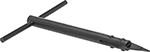
Key-Locking Threaded Insert Drivers
 |
For Thread Size | For Tap Thread Size | Handle Style | Each | ||||||||||||||||||||||||||||||||||||||||||||||||||||||||||||||||||||||||||||||||||||||||||||||||
|---|---|---|---|---|---|---|---|---|---|---|---|---|---|---|---|---|---|---|---|---|---|---|---|---|---|---|---|---|---|---|---|---|---|---|---|---|---|---|---|---|---|---|---|---|---|---|---|---|---|---|---|---|---|---|---|---|---|---|---|---|---|---|---|---|---|---|---|---|---|---|---|---|---|---|---|---|---|---|---|---|---|---|---|---|---|---|---|---|---|---|---|---|---|---|---|---|---|---|---|
Metric Thread | |||||||||||||||||||||||||||||||||||||||||||||||||||||||||||||||||||||||||||||||||||||||||||||||||||
For Thick-Wall Inserts | |||||||||||||||||||||||||||||||||||||||||||||||||||||||||||||||||||||||||||||||||||||||||||||||||||
| M20 | M30 | Straight | 94010A355 | 000000 | |||||||||||||||||||||||||||||||||||||||||||||||||||||||||||||||||||||||||||||||||||||||||||||||
Helical Threaded Inserts
 |
Pronged |
Restore, reinforce, or create threads in metal. The tough coils on these inserts expand once installed to anchor in a tapped hole. Also known as Heli-Coil inserts, they're often used in engine heads and machinery housings where strong connections are critical. Unlike threadlocking inserts, you can remove and reuse them without them losing their strength.
Installation requires a drill bit, a helical insert tap, and an installation tool.
Pronged—The prong attaches to an installation tool for precise control as you drive inserts in. Remove the prong with a punch or break-off tool before inserting a screw.
18-8 Stainless Steel—The choice for wet and outdoor environments, these inserts resist rust and mild chemicals.
Inserts | Through-Hole Taps | Closed-End Hole Taps | Installation Tools | Inserts with Installation Tools | |||||||||||||||||||||||||||||||||||||||||||||||||||||||||||||||||||||||||||||||||||||||||||||||
|---|---|---|---|---|---|---|---|---|---|---|---|---|---|---|---|---|---|---|---|---|---|---|---|---|---|---|---|---|---|---|---|---|---|---|---|---|---|---|---|---|---|---|---|---|---|---|---|---|---|---|---|---|---|---|---|---|---|---|---|---|---|---|---|---|---|---|---|---|---|---|---|---|---|---|---|---|---|---|---|---|---|---|---|---|---|---|---|---|---|---|---|---|---|---|---|---|---|---|---|
Thread Size | Installed Lg., mm | Drill Bit Size | For Max. Hole Dia. | Specs. Met | Pkg. Qty. | Pkg. | Each | Each | Each | No. of Inserts Included | Each | ||||||||||||||||||||||||||||||||||||||||||||||||||||||||||||||||||||||||||||||||||||||||
Pronged | |||||||||||||||||||||||||||||||||||||||||||||||||||||||||||||||||||||||||||||||||||||||||||||||||||
18-8 Stainless Steel | |||||||||||||||||||||||||||||||||||||||||||||||||||||||||||||||||||||||||||||||||||||||||||||||||||
| M30 x 3.5 mm | 45 | 1 7/32" | 1.219" | SAE MA3279-183 | 1 | 92450A145 | 00000 | 92450A345 | 0000000 | 91709A350 | 0000000 | 92450A543 | 000000 | 5 | 91732A972 | 0000000 | |||||||||||||||||||||||||||||||||||||||||||||||||||||||||||||||||||||||||||||||||||
Helical Insert Taps
Helical Threaded Insert Installation and Prong Break-Off Tools
T-Handle |
For Thread Size | Handle Style | Each | |||||||||||||||||||||||||||||||||||||||||||||||||||||||||||||||||||||||||||||||||||||||||||||||||
|---|---|---|---|---|---|---|---|---|---|---|---|---|---|---|---|---|---|---|---|---|---|---|---|---|---|---|---|---|---|---|---|---|---|---|---|---|---|---|---|---|---|---|---|---|---|---|---|---|---|---|---|---|---|---|---|---|---|---|---|---|---|---|---|---|---|---|---|---|---|---|---|---|---|---|---|---|---|---|---|---|---|---|---|---|---|---|---|---|---|---|---|---|---|---|---|---|---|---|---|
Metric Thread | |||||||||||||||||||||||||||||||||||||||||||||||||||||||||||||||||||||||||||||||||||||||||||||||||||
| M30 × 3.5 mm | T-Handle | 92450A543 | 000000 | ||||||||||||||||||||||||||||||||||||||||||||||||||||||||||||||||||||||||||||||||||||||||||||||||
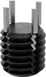
Screw-Locking Helical Threaded Inserts
 |
Pronged |
The irregularly shaped threads tightly grip screws to prevent them from loosening or backing out under vibration. Use these inserts to create or repair threads in pumps and other machinery that shakes and rattles. Also known as Heli-Coil inserts.
Installation requires a drill bit, a helical insert tap, and an installation tool.
Pronged—The prong attaches to an installation tool for precise control as you drive inserts in. Remove the prong with a punch or break-off tool before inserting a screw.
18-8 Stainless Steel—The choice for wet and outdoor environments, these inserts resist rust and mild chemicals.
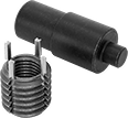
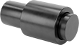
Key-Locking Threaded Insert Installation Tools
 |  |
Style A | Style D |
Thread inserts and drive down their keys with a single tool. These tools are compatible with Keensert inserts.
Threaded Insert Installation Tools
|
Style A |
For Thread Size | For Tap Thread Size | Style | Features | Each | |||||||||||||||||||||||||||||||||||||||||||||||||||||||||||||||||||||||||||||||||||||||||||||||
|---|---|---|---|---|---|---|---|---|---|---|---|---|---|---|---|---|---|---|---|---|---|---|---|---|---|---|---|---|---|---|---|---|---|---|---|---|---|---|---|---|---|---|---|---|---|---|---|---|---|---|---|---|---|---|---|---|---|---|---|---|---|---|---|---|---|---|---|---|---|---|---|---|---|---|---|---|---|---|---|---|---|---|---|---|---|---|---|---|---|---|---|---|---|---|---|---|---|---|---|
For Thick-Wall Inserts | |||||||||||||||||||||||||||||||||||||||||||||||||||||||||||||||||||||||||||||||||||||||||||||||||||
| M20 | M30 | A | Slotted End | 6721N91 | 000000 | ||||||||||||||||||||||||||||||||||||||||||||||||||||||||||||||||||||||||||||||||||||||||||||||
Threaded Insert Installation Tools with Spring
|
Style D |
For Thread Size | For Tap Thread Size | Style | Features | Each | |||||||||||||||||||||||||||||||||||||||||||||||||||||||||||||||||||||||||||||||||||||||||||||||
|---|---|---|---|---|---|---|---|---|---|---|---|---|---|---|---|---|---|---|---|---|---|---|---|---|---|---|---|---|---|---|---|---|---|---|---|---|---|---|---|---|---|---|---|---|---|---|---|---|---|---|---|---|---|---|---|---|---|---|---|---|---|---|---|---|---|---|---|---|---|---|---|---|---|---|---|---|---|---|---|---|---|---|---|---|---|---|---|---|---|---|---|---|---|---|---|---|---|---|---|
For Thick-Wall Inserts | |||||||||||||||||||||||||||||||||||||||||||||||||||||||||||||||||||||||||||||||||||||||||||||||||||
| M20 | M30 | D | Slotted End, Sleeve | 93904A796 | 000000 | ||||||||||||||||||||||||||||||||||||||||||||||||||||||||||||||||||||||||||||||||||||||||||||||
T-Slot Nuts
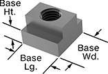 |
Metric
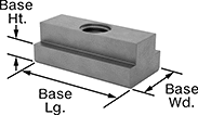
Base, mm | Fully Threaded | ||||||||||||||||||||||||||||||||||||||||||||||||||||||||||||||||||||||||||||||||||||||||||||||||||
|---|---|---|---|---|---|---|---|---|---|---|---|---|---|---|---|---|---|---|---|---|---|---|---|---|---|---|---|---|---|---|---|---|---|---|---|---|---|---|---|---|---|---|---|---|---|---|---|---|---|---|---|---|---|---|---|---|---|---|---|---|---|---|---|---|---|---|---|---|---|---|---|---|---|---|---|---|---|---|---|---|---|---|---|---|---|---|---|---|---|---|---|---|---|---|---|---|---|---|---|
For Slot Wd., mm | Thread Size | Lg. | Wd. | Ht. | Overall Ht., mm | Specs. Met | Each | ||||||||||||||||||||||||||||||||||||||||||||||||||||||||||||||||||||||||||||||||||||||||||||
Black-Oxide Steel | |||||||||||||||||||||||||||||||||||||||||||||||||||||||||||||||||||||||||||||||||||||||||||||||||||
| 36 | M30 × 3.5 mm | 54 | 54 | 22 | 44 | DIN 508 | 90510A238 | 000000 | |||||||||||||||||||||||||||||||||||||||||||||||||||||||||||||||||||||||||||||||||||||||||||
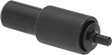
Key-Locking Threaded Insert Blank Drivers
 |
For Tap Thread Size | Handle Style | Each | |||||||||||||||||||||||||||||||||||||||||||||||||||||||||||||||||||||||||||||||||||||||||||||||||
|---|---|---|---|---|---|---|---|---|---|---|---|---|---|---|---|---|---|---|---|---|---|---|---|---|---|---|---|---|---|---|---|---|---|---|---|---|---|---|---|---|---|---|---|---|---|---|---|---|---|---|---|---|---|---|---|---|---|---|---|---|---|---|---|---|---|---|---|---|---|---|---|---|---|---|---|---|---|---|---|---|---|---|---|---|---|---|---|---|---|---|---|---|---|---|---|---|---|---|---|
Metric Thread | |||||||||||||||||||||||||||||||||||||||||||||||||||||||||||||||||||||||||||||||||||||||||||||||||||
| M30 | Straight | 93741A320 | 0000000 | ||||||||||||||||||||||||||||||||||||||||||||||||||||||||||||||||||||||||||||||||||||||||||||||||
Finish-Your-Own Key-Locking Threaded Inserts for Soft Metal
 |  |
Tap the thread size you need into the solid body of these inserts. They’re a great choice when you need a custom combination of internal thread size and external diameter. Use them to repair or add new threads in soft metal, such as aluminum. They can also plug threaded holes without the hassle of welding. Keys on the inserts drive into material to prevent slipping and rotating in the hole.
To install, drill and tap a hole in your material. Then, thread the insert onto the installation tool and screw it into the hole. Place the tool over the keys and hit it with a hammer to drive them in.
Black Phosphate-Coated Steel—These inserts resist occasional moisture.
%20--%3e%3cg%3e%3cg%20id='Layer_1'%3e%3cpath%20class='cls-1'%20d='M68,27.2c-14.6,0-26.4,11.7-26.4,26.3,0,7,2.8,13.7,7.7,18.7v44.8l18.8-16.1,18.7,16.1v-44.9c10.3-10.3,10.3-27,0-37.3-5-4.9-11.7-7.7-18.7-7.7h0ZM81.3,105l-13.2-11.4-13.2,11.4v-28.7c8.2,4.8,18.3,4.8,26.5,0v28.7ZM76.2,70.8c-5.2,2.5-11.2,2.5-16.4,0-9.5-4.5-13.5-15.9-9-25.4,4.5-9.5,15.9-13.5,25.4-9,9.5,4.5,13.5,15.9,9,25.4-1.9,4-5.1,7.1-9,9Z'/%3e%3cpath%20class='cls-2'%20d='M5.8,95.5c-1.2,0-2.1-1-2.1-2.1,0,0,0,0,0,0V29.4h20.9c2.1,0,3.8-1.7,3.8-3.8V3.7c.2,0,.4,0,.5,0h37.5c1.2,0,2.1,1,2.1,2.1v18.6c1.2,0,2.5.1,3.7.3V5.8C72.2,2.6,69.6,0,66.4,0H28.9c-1.5,0-3,.6-4.1,1.7h-.1c0,.1-23,23.2-23,23.2-1.1,1.1-1.7,2.6-1.7,4.1v64.3c0,3.2,2.6,5.8,5.8,5.8h41.7v-3.7H5.8ZM24.7,7.1v18.7H6L24.7,7.1Z'/%3e%3c/g%3e%3c/g%3e%3c/svg%3e)
Certificates with a traceable lot number are available for these products. Download certificates from ORDER HISTORY after your order ships.
Extra-Long T-Slot Nuts
Metric
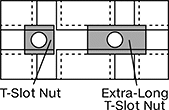 |  |
T-Slot Nut and Extra-Long T-Slot Nut Shown Installed Within Cross-Slot |
Base, mm | Fully Threaded | ||||||||||||||||||||||||||||||||||||||||||||||||||||||||||||||||||||||||||||||||||||||||||||||||||
|---|---|---|---|---|---|---|---|---|---|---|---|---|---|---|---|---|---|---|---|---|---|---|---|---|---|---|---|---|---|---|---|---|---|---|---|---|---|---|---|---|---|---|---|---|---|---|---|---|---|---|---|---|---|---|---|---|---|---|---|---|---|---|---|---|---|---|---|---|---|---|---|---|---|---|---|---|---|---|---|---|---|---|---|---|---|---|---|---|---|---|---|---|---|---|---|---|---|---|---|
For Slot Wd., mm | Thread Size | Lg. | Wd. | Ht. | Overall Ht., mm | Specs. Met | Each | ||||||||||||||||||||||||||||||||||||||||||||||||||||||||||||||||||||||||||||||||||||||||||||
Steel | |||||||||||||||||||||||||||||||||||||||||||||||||||||||||||||||||||||||||||||||||||||||||||||||||||
| 36 | M30 × 3 mm | 108 | 54 | 22 | 44 | DIN 508 | 90894A261 | 000000 | |||||||||||||||||||||||||||||||||||||||||||||||||||||||||||||||||||||||||||||||||||||||||||
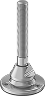
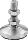
Seismic Stay-Put Swivel Leveling Mounts with Threaded Stud
 |
With Cushion |
Subjected to rigorous stress tests, these mounts withstand movement in every direction to minimize damage during an earthquake. After leveling your machine, bolt the mount to the floor and tighten the locking nut onto the base for added stability. The ball-and-socket joint in the base swivels to compensate for slightly sloped and pitted floors. For mounting versatility, you can install these mounts in either threaded holes or unthreaded through holes at the bottom of equipment.
304 Stainless Steel Base—The choice for most wet locations, these mounts can withstand repeated washdowns without corroding. However, they won't hold up to cleaning solutions that contain harsh chemicals like 316 stainless steel can.
Rubber Cushion—A cushion under the base protects floors from scrapes and gouges.
With Rubber Cushion | |||||||||||||||||||||||||||||||||||||||||||||||||||||||||||||||||||||||||||||||||||||||||||||||||||
|---|---|---|---|---|---|---|---|---|---|---|---|---|---|---|---|---|---|---|---|---|---|---|---|---|---|---|---|---|---|---|---|---|---|---|---|---|---|---|---|---|---|---|---|---|---|---|---|---|---|---|---|---|---|---|---|---|---|---|---|---|---|---|---|---|---|---|---|---|---|---|---|---|---|---|---|---|---|---|---|---|---|---|---|---|---|---|---|---|---|---|---|---|---|---|---|---|---|---|---|
Mounting Holes | Cap. per Mount, lb. | ||||||||||||||||||||||||||||||||||||||||||||||||||||||||||||||||||||||||||||||||||||||||||||||||||
Thread Size | Thread Lg. | Swivel Range of Motion | Base Dia. | No. of | Fasteners Included | Dia. | Ctr.-to-Ctr. Lg. | Specs. Met | Load | Pull | Overall Ht. | Cushion Material | Each | ||||||||||||||||||||||||||||||||||||||||||||||||||||||||||||||||||||||||||||||||||||||
304 Stainless Steel Base and Stud | |||||||||||||||||||||||||||||||||||||||||||||||||||||||||||||||||||||||||||||||||||||||||||||||||||
| M30 × 3.5 mm | 7 1/8" | 10° | 5 7/8" | 3 | No | 17/32" | 4 3/32" | NZS 4219 | 13,480 | 6,290 | 11 3/8" | Buna-N | 7750N111 | 0000000 | |||||||||||||||||||||||||||||||||||||||||||||||||||||||||||||||||||||||||||||||||||||
Swivel Leveling Mounts with Threaded Stud
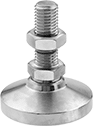 |  |
Without Cushion | With Cushion |
Keep equipment level on slightly sloped and pitted floors with mounts that have a ball-and-socket joint in the base. For mounting versatility, you can install them in either threaded holes or unthreaded through holes at the bottom of equipment.
Nickel-Plated Steel Base—With a shiny appearance, these mounts create a finished look. They're best for dry environments since the nickel plating offers minimal corrosion resistance.
Zinc-Yellow-Chromate-Plated Steel Base—More corrosion resistant than nickel-plated steel, these mounts are suitable for damp environments. However, they won’t hold up to chemical cleaners, high-pressure washdowns, and other harsh conditions like stainless steel can.
303 Stainless Steel Base—The choice for most wet locations, these mounts can withstand repeated washdowns without corroding. However, they won't hold up to cleaning solutions that contain harsh chemicals like 316 stainless steel can.
Rubber Cushion—A cushion under the base grips surfaces so vibrating equipment doesn't slide. It also protects floors from scrapes and gouges.
Without Cushion | With Rubber Cushion | ||||||||||||||||||||||||||||||||||||||||||||||||||||||||||||||||||||||||||||||||||||||||||||||||||
|---|---|---|---|---|---|---|---|---|---|---|---|---|---|---|---|---|---|---|---|---|---|---|---|---|---|---|---|---|---|---|---|---|---|---|---|---|---|---|---|---|---|---|---|---|---|---|---|---|---|---|---|---|---|---|---|---|---|---|---|---|---|---|---|---|---|---|---|---|---|---|---|---|---|---|---|---|---|---|---|---|---|---|---|---|---|---|---|---|---|---|---|---|---|---|---|---|---|---|---|
Thread Size | Thread Lg., mm | Swivel Range of Motion | Base Dia., mm | Cap. per Mount, lb. | Overall Ht., mm | Each | Cap. per Mount, lb. | Overall Ht., mm | Cushion Material | Each | |||||||||||||||||||||||||||||||||||||||||||||||||||||||||||||||||||||||||||||||||||||||||
Nickel-Plated Steel Base and Stud | |||||||||||||||||||||||||||||||||||||||||||||||||||||||||||||||||||||||||||||||||||||||||||||||||||
| M30 × 3.5 mm | 152 | 7.5° | 152 | 42,500 | 222 | 6111K661 | 0000000 | 32,250 | 225 | Natural Rubber | 6111K672 | 0000000 | |||||||||||||||||||||||||||||||||||||||||||||||||||||||||||||||||||||||||||||||||||||||
Zinc-Yellow-Chromate-Plated Steel Base and Stud | |||||||||||||||||||||||||||||||||||||||||||||||||||||||||||||||||||||||||||||||||||||||||||||||||||
| M30 × 3.5 mm | 152 | 7.5° | 152 | 42,990 | 222 | 6301K44 | 000000 | 32,295 | 225 | Natural Rubber | 6301K47 | 000000 | |||||||||||||||||||||||||||||||||||||||||||||||||||||||||||||||||||||||||||||||||||||||
303 Stainless Steel Base and Stud | |||||||||||||||||||||||||||||||||||||||||||||||||||||||||||||||||||||||||||||||||||||||||||||||||||
| M30 × 3.5 mm | 152 | 7.5° | 152 | — | — | ——— | 0 | 32,200 | 225 | Natural Rubber | 6301K121 | 000000 | |||||||||||||||||||||||||||||||||||||||||||||||||||||||||||||||||||||||||||||||||||||||
