


Filter by
Color
Container Type
Component
Export Control Classification Number (ECCN)
DFARS Specialty Metals
Mount Type
Specifications Met
Maximum Amount of Fluid Treated
Measures
Fixturing for Parts Inspection
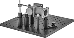 |
From towers and brackets to standoffs and supports, these components are the building blocks for your custom fixturing setup. They elevate parts so you can access a variety of angles for measuring and inspecting while protecting your measuring device from hitting the inspection table. You’ll often see them used with coordinate measuring machines (CMMs). They’re not for use in machining applications.
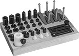
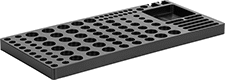
Kits
 |
No. of Pieces | Includes | Each | |||||||||||||||||||||||||||||||||||||||||||||||||||||||||||||||||||||||||||||||||||||||||||||||||
|---|---|---|---|---|---|---|---|---|---|---|---|---|---|---|---|---|---|---|---|---|---|---|---|---|---|---|---|---|---|---|---|---|---|---|---|---|---|---|---|---|---|---|---|---|---|---|---|---|---|---|---|---|---|---|---|---|---|---|---|---|---|---|---|---|---|---|---|---|---|---|---|---|---|---|---|---|---|---|---|---|---|---|---|---|---|---|---|---|---|---|---|---|---|---|---|---|---|---|---|
1/4"-20 Threads | |||||||||||||||||||||||||||||||||||||||||||||||||||||||||||||||||||||||||||||||||||||||||||||||||||
| 43 | 3 Hold-Down Clamps—1 9/16" Reach × 3" O'all Ht. 3 Hold-Down Clamps—2 5/16" Reach × 3" O'all Ht. 3 Standoffs—1/2" Dia. × 3/4" Ht. 3 Standoffs—1/2" Dia. × 2" Ht. 3 Standoffs—3/4" Dia. × 3/4" Ht. 3 Standoffs—3/4" Dia. × 2" Ht. 6 Standoffs—1/2" Dia. × 1" Ht. 6 Standoffs—3/4" Dia. × 1" Ht. 3 Pin Supports—1/2" Dia. × 1/2" Ht. 3 Pin Supports—3/4" Dia. × 1/2" Ht. 3 Cone Supports 1 Adjustable-Height Sleeve for Standoffs 2 Positioning Plates 1 Wood Stand | 1355N85 | 0000000 | ||||||||||||||||||||||||||||||||||||||||||||||||||||||||||||||||||||||||||||||||||||||||||||||||
| 63 | 3 Hold-Down Clamps—1 9/16" Reach × 3" O'all Ht. 3 Hold-Down Clamps—2 5/16" Reach × 3" O'all Ht. 2 Toggle Clamps with Mounting Plate 3 Standoffs—1/2" Dia. × 3/4" Ht. 3 Standoffs—1/2" Dia. × 2" Ht. 3 Standoffs—3/4" Dia. × 3/4" Ht. 3 Standoffs—3/4" Dia. × 2" Ht. 3 Standoffs—1" Dia. × 3/4" Ht. 3 Standoffs—1" Dia. × 2" Ht. 6 Standoffs—1/2" Dia. × 1" Ht. 6 Standoffs—3/4" Dia. × 1" Ht. 6 Standoffs—1" Dia. × 1" Ht. 1 Precision Adjustable-Height Standoff—1/2" Dia. 3 Pin Supports—1/2" Dia. × 1/2" Ht. 3 Pin Supports—3/4" Dia. × 1/2" Ht. 6 Cone Supports 2 Any-Angle Cone Supports 1 Adjustable-Height Sleeve for Standoffs 2 Positioning Plates 1 Wood Stand | 1355N95 | 00000000 | ||||||||||||||||||||||||||||||||||||||||||||||||||||||||||||||||||||||||||||||||||||||||||||||||
M6 Threads | |||||||||||||||||||||||||||||||||||||||||||||||||||||||||||||||||||||||||||||||||||||||||||||||||||
| 42 | 2 Hold-Down Clamps—38 mm Reach × 38 mm O'all Ht. 4 Hold-Down Clamps—58 mm Reach × 75 mm O'all Ht. 3 Standoffs—13 mm Dia. × 20 mm Ht. 3 Standoffs—13 mm Dia. × 25 mm Ht. 3 Standoffs—13 mm Dia. × 50 mm Ht. 3 Standoffs—19 mm Dia. × 20 mm Ht. 3 Standoffs—19 mm Dia. × 25 mm Ht. 3 Standoffs—19 mm Dia. × 50 mm Ht. 3 Standoffs—25 mm Dia. × 20 mm Ht. 3 Standoffs—25 mm Dia. × 25 mm Ht. 3 Standoffs—25 mm Dia. × 50 mm Ht. 1 Adjustable-Height Standoff—13 mm Dia. 2 Pin Supports—13 mm Dia. × 25 mm Ht. 3 Cone Supports 1 Positioning Plate—35 mm Lg. 1 Positioning Plate—76 mm Lg. 1 Acetal Plastic Tray | 1409N51 | 000000 | ||||||||||||||||||||||||||||||||||||||||||||||||||||||||||||||||||||||||||||||||||||||||||||||||
Natural Light Flaw-Detection Dye Kits
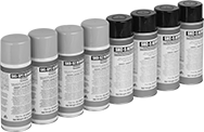 |
Use colored dye to reveal cracks and surface flaws in most nonporous material. Flaws become visible under natural light and appear as a bright red color. Commonly used for weld inspecting.
For Use On | Includes | Specs. Met | Mil. Spec. | Each | ||
|---|---|---|---|---|---|---|
| Carbide, Cast Iron, Ceramic, Stainless Steel, Steel | Four 16-oz. Aerosol Cans of Cleaner, Two 16-oz. Aerosol Cans of Developer, Two 16-oz. Aerosol Cans of Red Dye | ASTM E1417, SAE AMS2644 | MIL-STD-2132, MIL-STD-271 | 1383T3 | 0000000 |
Passivation Testers
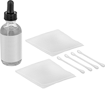 |
Test stainless steel to see if it needs to be passivated or was properly passivated. These tests detect the presence of iron from fabrication processes, which can limit stainless steel's inherent ability to resist corrosion. Often used in aerospace, pharmaceutical, and medical device industries, they meet ASTM, aerospace, and military passivation standards.
To perform a test, squeeze the dropper to apply the solution to the surface of a part. Keep the surface wet for six minutes before rinsing and drying it off. Do not scrub the solution off. If iron is detected, the surface will appear copper in color. If no copper coloring appears, the surface is clear of contaminants and is properly passivated. These bottles include enough solution to perform hundreds of spot tests.
This test is often used on all 200 and 300 series stainless steels and some 400 series stainless steel alloys. However, it’s not recommended to use this solution on 400 series stainless steel with less than 16% chromium. These stainless steel alloys will typically cause a false failure of the test.
Container | |||||||||
|---|---|---|---|---|---|---|---|---|---|
For Use On | Test Type | No. of Tests | Type | Size, fl. oz. | Includes | Specs. Met | Each | ||
| Stainless Steel | Analog | 200 | Bottle | 2 | Cloth, Copper-Sulfate Testing Solution, Cotton Swabs | ASTM A380, ASTM A967, ASTM B912, SAE AMS2700 | 7205N11 | 000000 | |
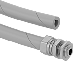
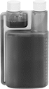
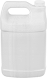
Leak-Detecting Dye for Water Systems
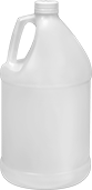 |  | |
Liquid, 1 pt. Container | Liquid, 1 gal. Container | Powder, 1 lb. Container Net Weight |
 |  | |
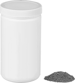
2 Tablets | 200 Tablets |
Easy-to-see colors enable you to visually inspect for leaks without ultraviolet light.
One gallon of water occupies 0.1337 cubic ft. Calculate the number of gallons a tank holds by dividing the tank volume by 0.1337.
Tablets—Tablets are easy to use for small volumes of water, such as toilets and septic systems. They dissolve in five minutes. Tablets that come in a packet include instructions for detecting a toilet leak.
Liquid—Liquid is a good choice for larger volumes of water, such as sewers. It disperses faster than tablets and powder.
Powder—Powder is the best choice for the largest volumes of water, such as ponds, piping systems in power plants, and cooling towers.
Fluorescent Orange, Fluorescent Red, and Fluorescent Yellow/Green—Fluorescent dye can be enhanced with a UV flashlight.
Container | |||||||||||||||||||||||||||||||||||||||||||||||||||||||||||||||||||||||||||||||||||||||||||||||||||
|---|---|---|---|---|---|---|---|---|---|---|---|---|---|---|---|---|---|---|---|---|---|---|---|---|---|---|---|---|---|---|---|---|---|---|---|---|---|---|---|---|---|---|---|---|---|---|---|---|---|---|---|---|---|---|---|---|---|---|---|---|---|---|---|---|---|---|---|---|---|---|---|---|---|---|---|---|---|---|---|---|---|---|---|---|---|---|---|---|---|---|---|---|---|---|---|---|---|---|---|
Color | Max. Amt. of Fluid Treated, gal. | No. of Tablets | Size | Net Wt., lb. | Type | Food Industry Std. | Includes | Each | |||||||||||||||||||||||||||||||||||||||||||||||||||||||||||||||||||||||||||||||||||||||||||
Tablets | |||||||||||||||||||||||||||||||||||||||||||||||||||||||||||||||||||||||||||||||||||||||||||||||||||
| Blue | 4 | 2 | — | — | Packet | NSF/ANSI 60 | Instructions | 1400T33 | 00000 | ||||||||||||||||||||||||||||||||||||||||||||||||||||||||||||||||||||||||||||||||||||||||||
| Blue | 4,000 | 200 | — | — | Jar | NSF/ANSI 60 | — | 1400T32 | 00000 | ||||||||||||||||||||||||||||||||||||||||||||||||||||||||||||||||||||||||||||||||||||||||||
| Fluorescent Orange | 7,000 | 200 | — | — | Jar | NSF/ANSI 60 | — | 1400T31 | 00000 | ||||||||||||||||||||||||||||||||||||||||||||||||||||||||||||||||||||||||||||||||||||||||||
| Fluorescent Red | 12,000 | 200 | — | — | Jar | NSF/ANSI 60 | — | 1400T43 | 00000 | ||||||||||||||||||||||||||||||||||||||||||||||||||||||||||||||||||||||||||||||||||||||||||
| Fluorescent Yellow/Green | 12,000 | 200 | — | — | Jar | NSF/ANSI 60 | — | 1400T12 | 00000 | ||||||||||||||||||||||||||||||||||||||||||||||||||||||||||||||||||||||||||||||||||||||||||
Liquid | |||||||||||||||||||||||||||||||||||||||||||||||||||||||||||||||||||||||||||||||||||||||||||||||||||
| Blue | 12,500 | — | 1 pt. | — | Bottle | NSF/ANSI 60 | — | 1400T36 | 00000 | ||||||||||||||||||||||||||||||||||||||||||||||||||||||||||||||||||||||||||||||||||||||||||
| Blue | 100,000 | — | 1 gal. | — | Jug | NSF/ANSI 60 | — | 1400T37 | 00000 | ||||||||||||||||||||||||||||||||||||||||||||||||||||||||||||||||||||||||||||||||||||||||||
| Fluorescent Orange | 4,000 | — | 1 pt. | — | Bottle | NSF/ANSI 60 | — | 1400T34 | 00000 | ||||||||||||||||||||||||||||||||||||||||||||||||||||||||||||||||||||||||||||||||||||||||||
| Fluorescent Orange | 32,000 | — | 1 gal. | — | Jug | NSF/ANSI 60 | — | 1400T35 | 00000 | ||||||||||||||||||||||||||||||||||||||||||||||||||||||||||||||||||||||||||||||||||||||||||
| Fluorescent Red | 3,125 | — | 1 pt. | — | Bottle | NSF/ANSI 60 | — | 1400T44 | 00000 | ||||||||||||||||||||||||||||||||||||||||||||||||||||||||||||||||||||||||||||||||||||||||||
| Fluorescent Red | 25,000 | — | 1 gal. | — | Jug | NSF/ANSI 60 | — | 1400T46 | 000000 | ||||||||||||||||||||||||||||||||||||||||||||||||||||||||||||||||||||||||||||||||||||||||||
| Fluorescent Yellow/Green | 12,500 | — | 1 pt. | — | Bottle | NSF/ANSI 60 | — | 1400T45 | 00000 | ||||||||||||||||||||||||||||||||||||||||||||||||||||||||||||||||||||||||||||||||||||||||||
| Fluorescent Yellow/Green | 100,000 | — | 1 gal. | — | Jug | NSF/ANSI 60 | — | 1400T49 | 00000 | ||||||||||||||||||||||||||||||||||||||||||||||||||||||||||||||||||||||||||||||||||||||||||
Powder | |||||||||||||||||||||||||||||||||||||||||||||||||||||||||||||||||||||||||||||||||||||||||||||||||||
| Fluorescent Red | 60,000 | — | — | 1 | Jar | NSF/ANSI 60 | — | 1400T38 | 000000 | ||||||||||||||||||||||||||||||||||||||||||||||||||||||||||||||||||||||||||||||||||||||||||
| Fluorescent Yellow/Green | 120,000 | — | — | 1 | Jar | NSF/ANSI 60 | — | 1400T52 | 000000 | ||||||||||||||||||||||||||||||||||||||||||||||||||||||||||||||||||||||||||||||||||||||||||
UV Light Flaw-Detection Dye Kits
 |
More sensitive than natural light kits, these kits use UV light with colored dye to detect cracks, seams, and pores on machined surfaces.
Light | |||||||||||||
|---|---|---|---|---|---|---|---|---|---|---|---|---|---|
For Use On | Includes | Bulb Type | Wattage, W | Voltage, V AC | Connection Type | Electrical Connection | No. of Blades | Cord Lg., ft. | Specs. Met | Mil. Spec. | Each | ||
| Carbide, Cast Iron, Ceramic, Stainless Steel, Steel | One 16-oz Aerosol Can of Fluorescent Green Dye, One 16-oz. Can of Developer, Two 16-oz. Aerosol Cans of Cleaner, UV Light | Ultraviolet | 5 | 120 | Plug In | Straight Blade | 3 | 9 | ASTM E1417, SAE AMS2644 | MIL-STD-2132, MIL-STD-271 | 1387T46 | 000000000 | |
Coordinate Measurement Machine Probes for CNC Lathes
Probes
 |
Coordinate Measurement Machine Probes | Replacement Batteries | ||||||||||||||||||||||||||||||||||||||||||||||||||||||||||||||||||||||||||||||||||||||||||||||||||
|---|---|---|---|---|---|---|---|---|---|---|---|---|---|---|---|---|---|---|---|---|---|---|---|---|---|---|---|---|---|---|---|---|---|---|---|---|---|---|---|---|---|---|---|---|---|---|---|---|---|---|---|---|---|---|---|---|---|---|---|---|---|---|---|---|---|---|---|---|---|---|---|---|---|---|---|---|---|---|---|---|---|---|---|---|---|---|---|---|---|---|---|---|---|---|---|---|---|---|---|
For Stylus | Trigger Force, N | ||||||||||||||||||||||||||||||||||||||||||||||||||||||||||||||||||||||||||||||||||||||||||||||||||
Dia., mm | Lg., mm | Thread Size | O'all Lg., mm | For Axis Measuring Direction | X- and Y-Axis | Z-Axis | Repeatability, mm | Max. Distance from Receiver, m | Enclosure Rating | Manufacturer (Series) | Each | Pkg. Qty. | Pkg. | ||||||||||||||||||||||||||||||||||||||||||||||||||||||||||||||||||||||||||||||||||||||
Infrared | |||||||||||||||||||||||||||||||||||||||||||||||||||||||||||||||||||||||||||||||||||||||||||||||||||
| 40 | 58 | M4 | 50 to 150 | ±X, ±Y, +Z | 0.4, 0.8 | 5.3 | -0.001 to 0.001 | 5 | IK02, IP08 | Renishaw (OLP40) | 6192N11 | 000000000 | 1 | 6951K59 | 00000 | ||||||||||||||||||||||||||||||||||||||||||||||||||||||||||||||||||||||||||||||||||||
Radio | |||||||||||||||||||||||||||||||||||||||||||||||||||||||||||||||||||||||||||||||||||||||||||||||||||
| 40 | 58 | M4 | 50 to 150 | ±X, ±Y, +Z | 0.6, 0.97 | 6.23 | -0.001 to 0.001 | 15 | IK02, IP08 | Renishaw (RLP40-QE) | 6192N12 | 00000000 | 1 | 6951K59 | 0000 | ||||||||||||||||||||||||||||||||||||||||||||||||||||||||||||||||||||||||||||||||||||
 |
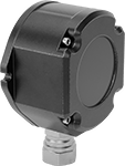
Receiver |
For Infrared Probes—Infrared probes send data to a receiver up to 5 meters away, but because they use light, they need a clear view. These probes are typically found in small lathes with chuck sizes around 8” and medium lathes with chuck sizes around 15”. They can also be used on a 5-axis CNC with a table size under 1,500 mm.
Component | For Max. No. of Probes | Wire Connection | Cord Lg., ft. | Manufacturer (Series) | Each | ||||||||||||||||||||||||||||||||||||||||||||||||||||||||||||||||||||||||||||||||||||||||||||||
|---|---|---|---|---|---|---|---|---|---|---|---|---|---|---|---|---|---|---|---|---|---|---|---|---|---|---|---|---|---|---|---|---|---|---|---|---|---|---|---|---|---|---|---|---|---|---|---|---|---|---|---|---|---|---|---|---|---|---|---|---|---|---|---|---|---|---|---|---|---|---|---|---|---|---|---|---|---|---|---|---|---|---|---|---|---|---|---|---|---|---|---|---|---|---|---|---|---|---|---|
For Infrared Probes | |||||||||||||||||||||||||||||||||||||||||||||||||||||||||||||||||||||||||||||||||||||||||||||||||||
| Receiver | 4 | Wire Leads | 82 | Renishaw (OMM-2) | 6206N13 | 000000000 | |||||||||||||||||||||||||||||||||||||||||||||||||||||||||||||||||||||||||||||||||||||||||||||
 |
Interface |
Component | Wire Connection | Manufacturer (Series) | Each | ||||||||||||||||||||||||||||||||||||||||||||||||||||||||||||||||||||||||||||||||||||||||||||||||
|---|---|---|---|---|---|---|---|---|---|---|---|---|---|---|---|---|---|---|---|---|---|---|---|---|---|---|---|---|---|---|---|---|---|---|---|---|---|---|---|---|---|---|---|---|---|---|---|---|---|---|---|---|---|---|---|---|---|---|---|---|---|---|---|---|---|---|---|---|---|---|---|---|---|---|---|---|---|---|---|---|---|---|---|---|---|---|---|---|---|---|---|---|---|---|---|---|---|---|---|
For Infrared Probes | |||||||||||||||||||||||||||||||||||||||||||||||||||||||||||||||||||||||||||||||||||||||||||||||||||
| Interface | Screw Terminal | Renishaw (OSI) | 6206N14 | 000000000 | |||||||||||||||||||||||||||||||||||||||||||||||||||||||||||||||||||||||||||||||||||||||||||||||
 |
Receiver/Interface |
For Infrared Probes—Infrared probes send data to a receiver up to 5 meters away, but because they use light, they need a clear view. These probes are typically found in small lathes with chuck sizes around 8” and medium lathes with chuck sizes around 15”. They can also be used on a 5-axis CNC with a table size under 1,500 mm.
For Radio Probes—Radio probes send data to a receiver up to 15 meters away. They block out interference from other radio devices, so you can use multiple radio probes in one machine shop. They’re used in small, medium, and large lathes with a chuck size up to 24". They can also be used on a 5-axis CNC with a table size under 3,500 mm.
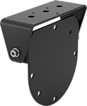 |
Receiver mounting brackets make it easy to attach a receiver or receiver/interface to your lathe.
Color | Material | Mounting Fasteners Included | Mfr. | Mfr. Model No. | Each | ||
|---|---|---|---|---|---|---|---|
| Black | Powder-Coated Steel | Yes | Renishaw | A-2033-0830 | 6206N21 | 0000000 |
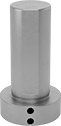 |
Use a shank to attach a probe to the spindle on your CNC lathe.
 |
Conduit Trade Size | Cord Lg., ft. | Mfr. | Mfr. Model No. | Each | ||
|---|---|---|---|---|---|---|
| 5/16 | 3 | Renishaw | A-4113-0306 | 6206N15 | 000000 |
Coordinate Measurement Machine Probes for CNC Machines
Probes
 |
Infrared—Infrared probes send data to a receiver up to 5 meters away, but because they use light, they need a clear view.
Radio— Radio probes send data to a receiver up to 15 meters away. They block out interference from other radio devices, so you can use multiple radio probes in one machine shop.
40 mm Diameter—40 mm probes are typically found in small and medium machines with a chuck size between 6" and 15".
63 mm Diameter—63 mm probes are typically found in medium to large machines with a chuck size between 10" and 24".
Coordinate Measurement Machine Probes | Replacement Batteries | ||||||||||||||||||||||||||||||||||||||||||||||||||||||||||||||||||||||||||||||||||||||||||||||||||
|---|---|---|---|---|---|---|---|---|---|---|---|---|---|---|---|---|---|---|---|---|---|---|---|---|---|---|---|---|---|---|---|---|---|---|---|---|---|---|---|---|---|---|---|---|---|---|---|---|---|---|---|---|---|---|---|---|---|---|---|---|---|---|---|---|---|---|---|---|---|---|---|---|---|---|---|---|---|---|---|---|---|---|---|---|---|---|---|---|---|---|---|---|---|---|---|---|---|---|---|
For Stylus | Trigger Force, N | ||||||||||||||||||||||||||||||||||||||||||||||||||||||||||||||||||||||||||||||||||||||||||||||||||
Dia., mm | Lg., mm | Thread Size | O'all Lg., mm | For Axis Measuring Direction | X- and Y-Axis | Z-Axis | Repeatability, mm | Max. Distance from Receiver, m | Enclosure Rating | Manufacturer (Series) | Each | Pkg. Qty. | Pkg. | ||||||||||||||||||||||||||||||||||||||||||||||||||||||||||||||||||||||||||||||||||||||
Infrared | |||||||||||||||||||||||||||||||||||||||||||||||||||||||||||||||||||||||||||||||||||||||||||||||||||
| 40 | 50 | M4 | 50 to 150 | ±X, ±Y, +Z | 0.5, 0.9 | 5.85 | -0.001 to 0.001 | 5 | IK01, IP08 | Renishaw (OMP40) | 6206N11 | 000000000 | 1 | 6951K59 | 00000 | ||||||||||||||||||||||||||||||||||||||||||||||||||||||||||||||||||||||||||||||||||||
| 63 | 76 | M4 | 50 to 150 | ±X, ±Y, +Z | 0.75, 1.4 | 5.3 | -0.001 to 0.001 | 6 | IP08 | Renishaw (OMP60) | 6206N12 | 00000000 | 1 | 6951K57 | 0000 | ||||||||||||||||||||||||||||||||||||||||||||||||||||||||||||||||||||||||||||||||||||
Radio | |||||||||||||||||||||||||||||||||||||||||||||||||||||||||||||||||||||||||||||||||||||||||||||||||||
| 40 | 50 | M4 | 50 to 150 | ±X, ±Y, +Z | 0.5, 0.9 | 5.85 | -0.001 to 0.001 | 15 | IK01, IP08 | Renishaw (RMP40-QE) | 6206N17 | 00000000 | 1 | 6951K59 | 0000 | ||||||||||||||||||||||||||||||||||||||||||||||||||||||||||||||||||||||||||||||||||||
| 63 | 76 | M4 | 50 to 150 | ±X, ±Y, +Z | 0.75, 1.4 | 5.3 | -0.001 to 0.001 | 15 | IP08 | Renishaw (RMP60-QE) | 6206N18 | 00000000 | 1 | 6951K57 | 0000 | ||||||||||||||||||||||||||||||||||||||||||||||||||||||||||||||||||||||||||||||||||||
|
Receiver |
For Infrared Probes—Infrared probes send data to a receiver up to 5 meters away, but because they use light, they need a clear view.
Component | For Max. No. of Probes | Wire Connection | Cord Lg., ft. | Manufacturer (Series) | Each | ||||||||||||||||||||||||||||||||||||||||||||||||||||||||||||||||||||||||||||||||||||||||||||||
|---|---|---|---|---|---|---|---|---|---|---|---|---|---|---|---|---|---|---|---|---|---|---|---|---|---|---|---|---|---|---|---|---|---|---|---|---|---|---|---|---|---|---|---|---|---|---|---|---|---|---|---|---|---|---|---|---|---|---|---|---|---|---|---|---|---|---|---|---|---|---|---|---|---|---|---|---|---|---|---|---|---|---|---|---|---|---|---|---|---|---|---|---|---|---|---|---|---|---|---|
For Infrared Probes | |||||||||||||||||||||||||||||||||||||||||||||||||||||||||||||||||||||||||||||||||||||||||||||||||||
| Receiver | 4 | Wire Leads | 82 | Renishaw (OMM-2) | 6206N13 | 000000000 | |||||||||||||||||||||||||||||||||||||||||||||||||||||||||||||||||||||||||||||||||||||||||||||
|
Interface |
Component | Wire Connection | Manufacturer (Series) | Each | ||||||||||||||||||||||||||||||||||||||||||||||||||||||||||||||||||||||||||||||||||||||||||||||||
|---|---|---|---|---|---|---|---|---|---|---|---|---|---|---|---|---|---|---|---|---|---|---|---|---|---|---|---|---|---|---|---|---|---|---|---|---|---|---|---|---|---|---|---|---|---|---|---|---|---|---|---|---|---|---|---|---|---|---|---|---|---|---|---|---|---|---|---|---|---|---|---|---|---|---|---|---|---|---|---|---|---|---|---|---|---|---|---|---|---|---|---|---|---|---|---|---|---|---|---|
For Infrared Probes | |||||||||||||||||||||||||||||||||||||||||||||||||||||||||||||||||||||||||||||||||||||||||||||||||||
| Interface | Screw Terminal | Renishaw (OSI) | 6206N14 | 000000000 | |||||||||||||||||||||||||||||||||||||||||||||||||||||||||||||||||||||||||||||||||||||||||||||||
|
Receiver/Interface |
For Infrared Probes—Infrared probes send data to a receiver up to 5 meters away, but because they use light, they need a clear view.
For Radio Probes— Radio probes send data to a receiver up to 15 meters away. They block out interference from other radio devices, so you can use multiple radio probes in one machine shop.
|
Receiver mounting brackets make it easy to attach a receiver or receiver/interface to your machine.
Color | Material | Mounting Fasteners Included | Mfr. | Mfr. Model No. | Each | ||
|---|---|---|---|---|---|---|---|
| Black | Powder-Coated Steel | Yes | Renishaw | A-2033-0830 | 6206N21 | 0000000 |
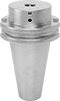 |
For Probe Dia., mm | Shank Type | For Probe Mfr. Series | Mfr. | Mfr. Model No. | Each | ||
|---|---|---|---|---|---|---|---|
| 40 | BT 40 Taper | OMP40, RMP40-QE | Renishaw | M-4071-0057 | 6206N26 | 0000000 | |
| 40 | BT 50 Taper | OMP40, RMP40-QE | Renishaw | M-4071-0071 | 6206N27 | 000000 | |
| 40 | CAT 40 Taper | OMP40, RMP40-QE | Renishaw | M-4071-0058 | 6206N22 | 000000 | |
| 40 | CAT 50 Taper | OMP40, RMP40-QE | Renishaw | M-4071-0072 | 6206N23 | 000000 | |
| 63 | BT 40 Taper | OMP60, RMP60-QE | Renishaw | M-2045-0027 | 6206N28 | 000000 | |
| 63 | BT 50 Taper | OMP60, RMP60-QE | Renishaw | M-2045-0073 | 6206N29 | 000000 | |
| 63 | CAT 40 Taper | OMP60, RMP60-QE | Renishaw | M-2045-0069 | 6206N24 | 000000 | |
| 63 | CAT 50 Taper | OMP60, RMP60-QE | Renishaw | M-2045-0071 | 6206N25 | 000000 |
 |
Add a shank adapter to fit 40 mm probes to shanks made for 63 mm probes.
For Probe Manufacturer Series | Compatible with Shanks for Probe Manufacturer Series | Mfr. | Mfr. Model No. | Each | ||
|---|---|---|---|---|---|---|
| OMP40, RMP40-QE | MP11, MP12, MP700, MP700E, OMP60, RMP60-QE | Renishaw | A-4071-0031 | 6206N16 | 0000000 |
|
Conduit Trade Size | Cord Lg., ft. | Mfr. | Mfr. Model No. | Each | ||
|---|---|---|---|---|---|---|
| 5/16 | 3 | Renishaw | A-4113-0306 | 6206N15 | 000000 |
Modular Coordinate Measurement Machine Probes
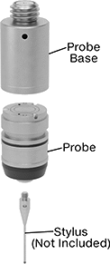 |
Probe Base and Probe Sold Separately |
Swap out Renishaw probe styles to inspect different features on a part without having to recalibrate. These probes mount magnetically to a base that threads into your coordinate measuring machine (CMM), making mid-inspection changes quick. They’re also known as modules. It’s easy to tell different styles apart from their different end colors. To take 3D measurements, they record the coordinates of different points on your workpiece. Because this involves physically touching your workpiece, they’re more accurate than other automated measurement systems. They’re touch-trigger probes, the most common CMM probe type, which means they stop to record the coordinates of one point at a time. Use them to check distances, diameters, right angles, and the location of holes and grooves. However, they're not as good at checking complex features, flatness, or roundness.
All probes require a stylus as well as a base (sold separately for some probes).
Trigger force is the amount of force required for a probe to take a measurement and record it. Choose a probe with a force that is high enough to avoid false triggers from vibration but not so high it damages the workpiece and leads to inaccurate measurements.
Probe and Base Kits
 |
SF Series—SF series probes have a trigger force that works for most general purpose probing jobs where vibration is not an issue.
TP20 Series—TP20 probe bases have a magnetic proximity switch to prevent a probe from accidentally triggering when you’re attaching it or detaching it. However, probes attached to these bases can’t be used to inspect magnetic parts.
For Stylus | Trigger Force, N | |||||||||||||
|---|---|---|---|---|---|---|---|---|---|---|---|---|---|---|
No. of Pieces | Includes | Dia., mm | Thread Size | O'all Lg., mm | For Axis Measuring Direction | X- and Y-Axis | Z-Axis | End Color | Features | Manufacturer (Series) | Each | |||
| 3 | Two 20 mm Lg. SF Probes One 19 mm Lg. TP20 Probe Base | 13 | M2 | 10 to 50 | ±X, ±Y, +Z | 0.08 | 0.75 | Black | Magnetic Proximity Switch | Renishaw (SF, TP20) | 6179N11 | 000000000 | ||
 |
For Probe Mfr. Series | Mfr. | Mfr. Model No. | Each | ||
|---|---|---|---|---|---|
| TP20, TP20 NI | Renishaw | A-1042-1486 | 6179N23 | 000000 |
Probe Bases
Bases house the system that sends a signal to record a measurement. They thread onto probe heads with an M8 connection on your CMM.
TP20 Series—TP20 probe bases have a magnetic proximity switch to prevent a probe from accidentally triggering when you’re attaching it or detaching it. However, probes attached to these bases can’t be used to inspect magnetic parts.
TP20 NI Series—TP20 NI probe bases aren’t affected by magnetic fields, so they can be used to inspect magnetic parts. However, because they don’t have a magnetic proximity switch, you’ll need to program your CMM to stop taking measurements when you’re changing out probes.
Probes
For Stylus | Trigger Force, N | ||||||||||||||||||||||||||||||||||||||||||||||||||||||||||||||||||||||||||||||||||||||||||||||||||
|---|---|---|---|---|---|---|---|---|---|---|---|---|---|---|---|---|---|---|---|---|---|---|---|---|---|---|---|---|---|---|---|---|---|---|---|---|---|---|---|---|---|---|---|---|---|---|---|---|---|---|---|---|---|---|---|---|---|---|---|---|---|---|---|---|---|---|---|---|---|---|---|---|---|---|---|---|---|---|---|---|---|---|---|---|---|---|---|---|---|---|---|---|---|---|---|---|---|---|---|
Dia., mm | Lg., mm | Thread Size | O'all Lg., mm | For Axis Measuring Direction | X- and Y-Axis | Z-Axis | End Color | Each | |||||||||||||||||||||||||||||||||||||||||||||||||||||||||||||||||||||||||||||||||||||||||||
Renishaw (LF) | |||||||||||||||||||||||||||||||||||||||||||||||||||||||||||||||||||||||||||||||||||||||||||||||||||
| 13 | 20 | M2 | 10 to 30 | ±X, ±Y, +Z | 0.055 | 0.65 | Green | 6179N17 | 000000000 | ||||||||||||||||||||||||||||||||||||||||||||||||||||||||||||||||||||||||||||||||||||||||||
Renishaw (SF) | |||||||||||||||||||||||||||||||||||||||||||||||||||||||||||||||||||||||||||||||||||||||||||||||||||
| 13 | 20 | M2 | 10 to 50 | ±X, ±Y, +Z | 0.08 | 0.75 | Black | 6179N14 | 00000000 | ||||||||||||||||||||||||||||||||||||||||||||||||||||||||||||||||||||||||||||||||||||||||||
| 13 | 70 | M2 | 10 to 50 | ±X, ±Y, +Z | 0.08 | 0.75 | Black | 6179N19 | 00000000 | ||||||||||||||||||||||||||||||||||||||||||||||||||||||||||||||||||||||||||||||||||||||||||
| 13 | 95 | M2 | 10 to 50 | ±X, ±Y, +Z | 0.08 | 0.75 | Black | 6179N21 | 00000000 | ||||||||||||||||||||||||||||||||||||||||||||||||||||||||||||||||||||||||||||||||||||||||||
Renishaw (6W) | |||||||||||||||||||||||||||||||||||||||||||||||||||||||||||||||||||||||||||||||||||||||||||||||||||
| 13 | 24 | M2 | 10 to 30 | ±X, ±Y, ±Z | 0.14 | 1.6 | Blue | 6179N18 | 00000000 | ||||||||||||||||||||||||||||||||||||||||||||||||||||||||||||||||||||||||||||||||||||||||||
Renishaw (MF) | |||||||||||||||||||||||||||||||||||||||||||||||||||||||||||||||||||||||||||||||||||||||||||||||||||
| 13 | 20 | M2 | 10 to 60 | ±X, ±Y, +Z | 0.1 | 1.9 | Gray | 6179N15 | 00000000 | ||||||||||||||||||||||||||||||||||||||||||||||||||||||||||||||||||||||||||||||||||||||||||
Renishaw (EF) | |||||||||||||||||||||||||||||||||||||||||||||||||||||||||||||||||||||||||||||||||||||||||||||||||||
| 13 | 20 | M2 | 10 to 60 | ±X, ±Y, +Z | 0.1 | 3.2 | Brown | 6179N16 | 00000000 | ||||||||||||||||||||||||||||||||||||||||||||||||||||||||||||||||||||||||||||||||||||||||||
|
For Probe Mfr. Series | Mfr. | Mfr. Model No. | Each | ||
|---|---|---|---|---|---|
| TP20, TP20 NI | Renishaw | A-1042-1486 | 6179N23 | 000000 |
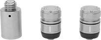
Modular Scanning Coordinate Measurement Machine Probes
Probe and Base Kits
 |  |
For Stylus | ||||||||||
|---|---|---|---|---|---|---|---|---|---|---|
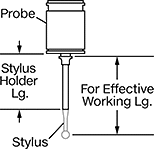
No. of Pieces | Includes | For Effective Working Lg., mm | Thread Size | O'all Lg., mm | For Axis Measuring Direction | Manufacturer (Series) | Each | |||
| 4 | One SM25-1 Probe Two SH25-1 Stylus Holders One SP25M Probe Base | 20 to 50 | M3 | 20 to 50 | ±X, ±Y, ±Z | Renishaw (SM25-1, SH25-1, SP25M) | 6191N11 | 0000000000 | ||
Probe Bases
Dia., mm | Lg., mm | Manufacturer (Series) | Each | |||
|---|---|---|---|---|---|---|
| 25 | 46 | Renishaw (SP25M) | 6191N24 | 000000000 | ||
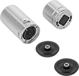
Probes
 |  | |
Stylus Holder | Probe |
Non-Linear Scanning Probes—Non-linear scanning probes work with angled styli and star styli, which probe in multiple directions.
Coordinate Measurement Machine Probes | Stylus Holders | ||||||||||||||||||||||||||||||||||||||||||||||||||||||||||||||||||||||||||||||||||||||||||||||||||
|---|---|---|---|---|---|---|---|---|---|---|---|---|---|---|---|---|---|---|---|---|---|---|---|---|---|---|---|---|---|---|---|---|---|---|---|---|---|---|---|---|---|---|---|---|---|---|---|---|---|---|---|---|---|---|---|---|---|---|---|---|---|---|---|---|---|---|---|---|---|---|---|---|---|---|---|---|---|---|---|---|---|---|---|---|---|---|---|---|---|---|---|---|---|---|---|---|---|---|---|
For Stylus | |||||||||||||||||||||||||||||||||||||||||||||||||||||||||||||||||||||||||||||||||||||||||||||||||||
For Effective Working Lg., mm | Dia., mm | Lg., mm | Thread Size | O'all Lg., mm | For Axis Measuring Direction | Manufacturer (Series) | Each | Lg., mm | Each | ||||||||||||||||||||||||||||||||||||||||||||||||||||||||||||||||||||||||||||||||||||||||||
Coordinate Measurement Machine Probes | |||||||||||||||||||||||||||||||||||||||||||||||||||||||||||||||||||||||||||||||||||||||||||||||||||
| 20 to 50 | 25 | 26 | M3 | 20 to 50 | ±X, ±Y, ±Z | Renishaw (SM25-1) | 6191N13 | 000000000 | 2.3 | 6191N18 | 0000000 | ||||||||||||||||||||||||||||||||||||||||||||||||||||||||||||||||||||||||||||||||||||||||
| 50 to 105 | 25 | 34 | M3 | 20 to 75 | ±X, ±Y, ±Z | Renishaw (SM25-2) | 6191N14 | 00000000 | 32.2 | 6191N19 | 000000 | ||||||||||||||||||||||||||||||||||||||||||||||||||||||||||||||||||||||||||||||||||||||||
| 120 to 200 | 25 | 48 | M3 | 20 to 100 | ±X, ±Y, ±Z | Renishaw (SM25-3) | 6191N15 | 00000000 | 102.2 | 6191N21 | 000000 | ||||||||||||||||||||||||||||||||||||||||||||||||||||||||||||||||||||||||||||||||||||||||
| 220 to 400 | 25 | 63 | M3 | 20 to 200 | ±X, ±Y, ±Z | Renishaw (SM25-4) | 6191N16 | 00000000 | 202.3 | 6191N22 | 000000 | ||||||||||||||||||||||||||||||||||||||||||||||||||||||||||||||||||||||||||||||||||||||||
Non-Linear Scanning Probes | |||||||||||||||||||||||||||||||||||||||||||||||||||||||||||||||||||||||||||||||||||||||||||||||||||
| 10 to 100 | 25 | 39 | M3 | 10 to 100 | ±X, ±Y, ±Z | Renishaw (SM25-5) | 6191N17 | 00000000 | 2.7 | 6191N23 | 000000 | ||||||||||||||||||||||||||||||||||||||||||||||||||||||||||||||||||||||||||||||||||||||||
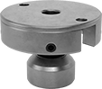
Touch-Trigger Probe Adapters
 |
Dia., mm | Lg., mm | For Probe Mfr. Series | Manufacturer (Series) | Each | |||
|---|---|---|---|---|---|---|---|
| 25 | 17 | LF, SF, 6W, MF, EF | Renishaw (TM25-20) | 6191N12 | 000000000 | ||
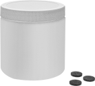
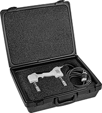
Battery-Powered Magnetic Particle Flaw Detection Kits
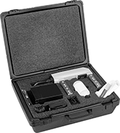 |
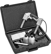
Check for defects slightly beneath the surface of ferrous materials that you wouldn’t otherwise see. The yoke in these kits is powered by a battery, so it uses direct current to create a strong magnetic field that reaches just below the surface of your part. When you apply the powder, the powder will move towards any flaws, helping you identify tears, cracks, and other imperfections.
Ideal for fieldwork, these kits come with everything you need for on-the-go inspections. The yoke lasts up to eight hours on a single battery charge. Built for rugged environments, it has a sealed design that stands up to chemicals and other harsh conditions.
For Use On | Includes | Battery Voltage, V DC | Batteries Included | Battery Charger Included | Specs. Met | Each | ||
|---|---|---|---|---|---|---|---|---|
| Cobalt, Iron, Nickel, Stainless Steel, Steel | One 1-lb. Bottle of Gray Powder | 6 | Yes | Yes | ASTM E1444 | 6081N11 | 000000000 |
Corner Weld Gauges
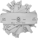 |
Also known as a fillet gauge, this gauge measures concave and convex corner weld dimensions.
Radius Measured | Measures | Material | Includes | Each | |||||||||||||||||||||||||||||||||||||||||||||||||||||||||||||||||||||||||||||||||||||||||||||||
|---|---|---|---|---|---|---|---|---|---|---|---|---|---|---|---|---|---|---|---|---|---|---|---|---|---|---|---|---|---|---|---|---|---|---|---|---|---|---|---|---|---|---|---|---|---|---|---|---|---|---|---|---|---|---|---|---|---|---|---|---|---|---|---|---|---|---|---|---|---|---|---|---|---|---|---|---|---|---|---|---|---|---|---|---|---|---|---|---|---|---|---|---|---|---|---|---|---|---|---|
MIG, TIG, Stick, Oxyacetylene Welding Process | |||||||||||||||||||||||||||||||||||||||||||||||||||||||||||||||||||||||||||||||||||||||||||||||||||
| 1/8", 3/16", 1/4", 5/16", 3/8", 7/16", 1/2", 5/8", 3/4", 7/8", 1", 3 mm, 5 mm, 6 mm, 8 mm, 10 mm, 11 mm, 13 mm, 16 mm, 19 mm, 22 mm, 25 mm | Concave Corners, Convex Corners | Steel | Vinyl Carrying Case | 7928A11 | 000000 | ||||||||||||||||||||||||||||||||||||||||||||||||||||||||||||||||||||||||||||||||||||||||||||||
Flaw Detecting Surface-Preparation Cleaners
Aerosol Can |
Remove oil, grease, and other contaminants that could alter results while inspecting for flaws. Originally made to meet aerospace standards, these cleaners dry fast without leaving a residue.
Container | Each | ||||||||||||||||||||||||||||||||||||||||||||||||||||||||||||||||||||||||||||||||||||||||||||||||||
|---|---|---|---|---|---|---|---|---|---|---|---|---|---|---|---|---|---|---|---|---|---|---|---|---|---|---|---|---|---|---|---|---|---|---|---|---|---|---|---|---|---|---|---|---|---|---|---|---|---|---|---|---|---|---|---|---|---|---|---|---|---|---|---|---|---|---|---|---|---|---|---|---|---|---|---|---|---|---|---|---|---|---|---|---|---|---|---|---|---|---|---|---|---|---|---|---|---|---|---|
Type | Net Wt., oz. | Solution Type | Harshness | For Use On | For Removing | Specs. Met | Mil. Spec. | 1-11 | 12-Up | ||||||||||||||||||||||||||||||||||||||||||||||||||||||||||||||||||||||||||||||||||||||||||
Sprays | |||||||||||||||||||||||||||||||||||||||||||||||||||||||||||||||||||||||||||||||||||||||||||||||||||
| Aerosol Can | 16 | Solvent Based | Harsh | Carbide, Ceramic, Cobalt, Iron, Nickel, Stainless Steel, Steel | Dust, Grease, Oil | ASTM E1417 | MIL-STD-2132, MIL-STD-271 | 1383T7 | 000000 | 000000 | |||||||||||||||||||||||||||||||||||||||||||||||||||||||||||||||||||||||||||||||||||||||||
Multicheck Weld Gauges
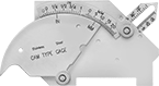 |
Check bevel angles, excess weld metal (capping size), length of a corner-weld leg, throat length, and depth of undercut.
Excess Weld Metal (Capping Size) | Corner-Weld Leg Lg. | Throat Lg. | Dp. of Undercut | ||||||||||||||||||||||||||||||||||||||||||||||||||||||||||||||||||||||||||||||||||||||||||||||||
|---|---|---|---|---|---|---|---|---|---|---|---|---|---|---|---|---|---|---|---|---|---|---|---|---|---|---|---|---|---|---|---|---|---|---|---|---|---|---|---|---|---|---|---|---|---|---|---|---|---|---|---|---|---|---|---|---|---|---|---|---|---|---|---|---|---|---|---|---|---|---|---|---|---|---|---|---|---|---|---|---|---|---|---|---|---|---|---|---|---|---|---|---|---|---|---|---|---|---|---|
Bevel Angle Measured | Max. Size Measured | Graduation Marks | Max. Lg. Measured | Graduation Marks | Max. Lg. Measured | Graduation Marks | Max. Size Measured | Graduation Marks | Material | Includes | Each | ||||||||||||||||||||||||||||||||||||||||||||||||||||||||||||||||||||||||||||||||||||||||
MIG, TIG, Stick, Oxyacetylene Welding Process | |||||||||||||||||||||||||||||||||||||||||||||||||||||||||||||||||||||||||||||||||||||||||||||||||||
| 0° to 60° | 1", 25 mm | 1/16", 1 mm | 1", 25 mm | 1/16", 1 mm | 3/4", 20 mm | 1/16", 1 mm | 3/16", 5 mm | 1/16", 1 mm | Stainless Steel | Vinyl Carrying Case | 7871A11 | 000000 | |||||||||||||||||||||||||||||||||||||||||||||||||||||||||||||||||||||||||||||||||||||||
Plug-In Magnetic Particle Flaw Detection Kits
 |
Find faulty seams, welding defects, and other surface-level flaws in ferrous materials. These kits come with everything you need to start inspecting parts. Apply the powder to the surface you want to inspect. Then plug in the yoke and it creates a magnetic field that draws the powder to the imperfection, making it easy to spot. Built for rugged environments, the yoke has a sealed design that stands up to chemicals and other harsh conditions. It’s also half the weight of a standard yoke and fits comfortably in your hand, so there’s less fatigue if you use it for extended periods of time.
Electrical | |||||||||
|---|---|---|---|---|---|---|---|---|---|
For Use On | Includes | Connection | No. of Blades | Voltage, V AC | Specs. Met | Mil. Spec. | Each | ||
| Cast Iron, Stainless Steel, Steel | One 1-lb. Bottle of Gray Powder, One 1-lb. Bottle of Red Powder | Straight Blade | 3 | 120 | ASTM E1444 | MIL-STD-2132, MIL-STD-271 | 1394T2 | 0000000 | |
Weld Alignment Gauges
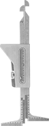 |
Measure internal misalignment of pipe ID, pipe wall thickness after tack welding, and go/no-go fit-up gap.
Internal Misalignment of Pipe ID | Pipe Wall Thick. After Tack Welding | ||||||||||||||||||||||||||||||||||||||||||||||||||||||||||||||||||||||||||||||||||||||||||||||||||
|---|---|---|---|---|---|---|---|---|---|---|---|---|---|---|---|---|---|---|---|---|---|---|---|---|---|---|---|---|---|---|---|---|---|---|---|---|---|---|---|---|---|---|---|---|---|---|---|---|---|---|---|---|---|---|---|---|---|---|---|---|---|---|---|---|---|---|---|---|---|---|---|---|---|---|---|---|---|---|---|---|---|---|---|---|---|---|---|---|---|---|---|---|---|---|---|---|---|---|---|
Max. Size Measured | Graduation Marks | Max. Thick. Measured | Graduation Marks | Go/No-Go Fit-Up Gap Size Measured Range | Material | Each | |||||||||||||||||||||||||||||||||||||||||||||||||||||||||||||||||||||||||||||||||||||||||||||
MIG, TIG, Stick, Oxyacetylene Welding Process | |||||||||||||||||||||||||||||||||||||||||||||||||||||||||||||||||||||||||||||||||||||||||||||||||||
| 1/16", 30 mm | 1/32", 1 mm | 1 3/4", 45 mm | 1/16", 1 mm | 1/16" to 3/32" | Stainless Steel | 8970A11 | 0000000 | ||||||||||||||||||||||||||||||||||||||||||||||||||||||||||||||||||||||||||||||||||||||||||||
Leak-Detecting Dye for Gasoline and Diesel Fuel Systems
Leak-Detecting Dye Kits for HVAC Systems
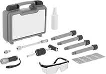 |
Dye Kit with Sealant |
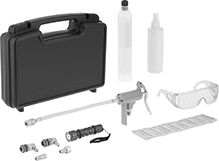 |
Dye Kit |
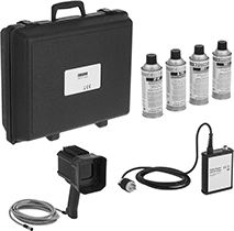
With bright-colored dye and a fully equipped kit, you have everything you need to spot leaks in your HVAC system. These kits come with the correct amount of dye required for your system's size. Inject the dye into your system and scan it with the UV light—the dye is fluorescent, so it’s easy to spot most leaks right away. For small leaks, let the dye circulate for 24 hours and then inspect it again. Use the dye cleaner before you fix a leak. If the repair isn’t sufficient, you’ll be able to spot more dye.
Four 0.5 oz. UV Dye and Sealant Containers—Kits with UV dye and sealant are formulated to seal hard-to-find leaks from the inside of your system. The dye and sealant formula is non-polymer and oil soluble, making it safe to stay in your system indefinitely. Reinforce seals from the outside for a permanent fix.
ANSI/ASHRAE Standard 86 and ANSI/ASHRAE Standard 97—Kits that meet ANSI/ASHRAE adhere to standards for chemical stability.
SAE J2297—Kits that meet SAE J2297 include dye that was originally made to detect leaks in automotive AC systems.
Dyes | Replacement Dyes | ||||||||||||||||||||||||||||||||||||||||||||||||||||||||||||||||||||||||||||||||||||||||||||||||||
|---|---|---|---|---|---|---|---|---|---|---|---|---|---|---|---|---|---|---|---|---|---|---|---|---|---|---|---|---|---|---|---|---|---|---|---|---|---|---|---|---|---|---|---|---|---|---|---|---|---|---|---|---|---|---|---|---|---|---|---|---|---|---|---|---|---|---|---|---|---|---|---|---|---|---|---|---|---|---|---|---|---|---|---|---|---|---|---|---|---|---|---|---|---|---|---|---|---|---|---|
Color | For Max. HVAC System Size, BTU/hr | Container Size, fl. oz. | Includes | Specs. Met | Each | Each | |||||||||||||||||||||||||||||||||||||||||||||||||||||||||||||||||||||||||||||||||||||||||||||
Liquid | |||||||||||||||||||||||||||||||||||||||||||||||||||||||||||||||||||||||||||||||||||||||||||||||||||
| Fluorescent Blue/Green | 168,000 | 0.5 | Four 0.5 oz. UV Dye and Sealant Containers, Adapter, Carrying Case, Cleaner, Hose Assembly, Injector, UV Light, UV Protective Glasses | ANSI/ASHRAE Standard 86, ANSI/ASHRAE Standard 97 | 7546N13 | 0000000 | 7546N14 | 000000 | |||||||||||||||||||||||||||||||||||||||||||||||||||||||||||||||||||||||||||||||||||||||||||
| Fluorescent Yellow | 760,000 | 8 | One 8 oz. UV Dye Container, Adapter, Carrying Case, Cleaner, Hose Assembly, Injector, UV Light, UV Protective Glasses | SAE J2297 | 7546N11 | 000000 | 7546N12 | 00000 | |||||||||||||||||||||||||||||||||||||||||||||||||||||||||||||||||||||||||||||||||||||||||||
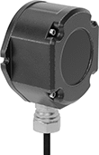
Plug-In Magnetic Yokes
 |
Find welding defects and other flaws in magnetic materials. These yokes create a magnetic field that draws magnetic powder (not included) to imperfections, making them easy to spot. All operate on AC power, which creates a small magnetic field ideal for detecting flaws along the surface of materials. Powered by standard electrical outlets, these yokes have a reliable and consistent power source.
Attach an LED light to your yoke to brightly illuminate inspection areas. They’re powered by the yoke’s magnetic field, so they don’t require batteries.
Calibrate your yoke before each use with a test weight to ensure accurate test results.
AC/DC Switch—Yokes with an AC/DC switch can also operate on DC power. DC power generates a deeper magnetic field than AC power to find defects underneath surfaces, such as internal tears and cracks.
6 lb.—6-lb. yokes are lightweight and fit comfortably in your hand to reduce fatigue over extended use.
Yokes | Test Weights | LED Light Attachments | Replacement Cords | ||||||||||||||
|---|---|---|---|---|---|---|---|---|---|---|---|---|---|---|---|---|---|
Voltage, V AC | Features | For Use On | Power Source | Cord Lg., ft. | Ht. | Lg. | Wt., lb. | Specs. Met | Each | Each | Each | Each | |||||
| 120 | — | Cobalt, Iron, Nickel, Stainless Steel, Steel | Electric | 12 | 7 1/2" | 12" | 6 | ASTM E1444 | 7096N12 | 0000000 | 7096N14 | 0000000 | 7096N13 | 0000000 | 7096N15 | 0000000 | |
| 120 | AC/DC Switch | Cobalt, Iron, Nickel, Stainless Steel, Steel | Electric | 12 | 7 1/2" | 12" | 8 | ASTM E1444 | 7096N11 | 00000000 | 7096N14 | 000000 | ——— | 0 | ——— | 0 | |
Leak-Detecting Dye for Hydraulic Systems
Container | |||||||||||||||||||||||||||||||||||||||||||||||||||||||||||||||||||||||||||||||||||||||||||||||||||
|---|---|---|---|---|---|---|---|---|---|---|---|---|---|---|---|---|---|---|---|---|---|---|---|---|---|---|---|---|---|---|---|---|---|---|---|---|---|---|---|---|---|---|---|---|---|---|---|---|---|---|---|---|---|---|---|---|---|---|---|---|---|---|---|---|---|---|---|---|---|---|---|---|---|---|---|---|---|---|---|---|---|---|---|---|---|---|---|---|---|---|---|---|---|---|---|---|---|---|---|
Color | Max. Amt. of Fluid Treated, gal. | Size | Type | Each | |||||||||||||||||||||||||||||||||||||||||||||||||||||||||||||||||||||||||||||||||||||||||||||||
Liquid | |||||||||||||||||||||||||||||||||||||||||||||||||||||||||||||||||||||||||||||||||||||||||||||||||||
| Red | 200 | 4 fl. oz. | Bottle | 1400T23 | 000000 | ||||||||||||||||||||||||||||||||||||||||||||||||||||||||||||||||||||||||||||||||||||||||||||||
| Red | 800 | 1 pt. | Bottle | 1400T101 | 00000 | ||||||||||||||||||||||||||||||||||||||||||||||||||||||||||||||||||||||||||||||||||||||||||||||
| Blue | 200 | 4 fl. oz. | Bottle | 1400T21 | 00000 | ||||||||||||||||||||||||||||||||||||||||||||||||||||||||||||||||||||||||||||||||||||||||||||||
| Blue | 800 | 1 pt. | Bottle | 1400T103 | 00000 | ||||||||||||||||||||||||||||||||||||||||||||||||||||||||||||||||||||||||||||||||||||||||||||||
| Fluorescent Red | 200 | 4 fl. oz. | Bottle | 1400T22 | 00000 | ||||||||||||||||||||||||||||||||||||||||||||||||||||||||||||||||||||||||||||||||||||||||||||||
| Fluorescent Red | 800 | 1 pt. | Bottle | 1400T102 | 000000 | ||||||||||||||||||||||||||||||||||||||||||||||||||||||||||||||||||||||||||||||||||||||||||||||
| Fluorescent Yellow | 200 | 4 fl. oz. | Bottle | 1400T104 | 00000 | ||||||||||||||||||||||||||||||||||||||||||||||||||||||||||||||||||||||||||||||||||||||||||||||
| Fluorescent Yellow | 800 | 1 pt. | Bottle | 1400T105 | 000000 | ||||||||||||||||||||||||||||||||||||||||||||||||||||||||||||||||||||||||||||||||||||||||||||||
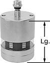
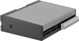
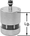
Torque Sensors
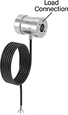 |
Measure and record manually applied torque. These sensors convert torque into an electrical signal that your computer or programmable logic controller (PLC) can read.
PC Connection Kits—Sensors with a PC connection kit include software that plots and analyzes measurements, so you can track highs, lows, and averages over time. If measurements fall outside a certain range, the software can also set off alarms or send you an email. Export your data to Excel, MATLAB, LabVIEW, and other programs for analysis. Connect to a computer or tablet with the included USB cord.
PLC Connection Kits—Sensors with a PLC connection kit send signals to a PLC to trigger actions in your system, such as checking for proper fastening between joints or connections. They can also trigger robotic arms and other machinery to apply a precise amount of force.
Wireless PC Connection Kits—Sensors with a wireless PC connection kit also have a built-in transmitter that uses Wi-Fi to send signals to a USB receiver plugged into your PC.
Accuracy | PC Connection Kits | PLC Connection Kits | Wireless PC Connection Kits | |||||||||||
|---|---|---|---|---|---|---|---|---|---|---|---|---|---|---|
Torque Range, N-m | N Torque Measuring Increments, N-m | Torque-Measuring Direction | Counterclockwise | Clockwise | Dia. | Ht. | Sensor Material | Each | Each | Each | ||||
| 0.1 to 6 | 0.01 | Clockwise and Counterclockwise | ±1% | ±1% | 1 1/2" | 2" | Aluminum | 7570N15 | 000000000 | 7570N19 | 000000000 | 7570N24 | 000000000 | |
| 0.1 to 10 | 0.01 | Clockwise and Counterclockwise | ±1% | ±1% | 1 1/2" | 2" | Aluminum | 7570N16 | 00000000 | 7570N21 | 00000000 | 7570N25 | 00000000 | |
| 0.1 to 60 | 0.06 | Clockwise and Counterclockwise | ±1% | ±1% | 1 1/2" | 2" | Aluminum | 7570N17 | 00000000 | 7570N22 | 00000000 | 7570N26 | 00000000 | |
| 0.1 to 150 | 0.15 | Clockwise and Counterclockwise | ±1% | ±1% | 1 1/2" | 2" | Aluminum | 7570N18 | 00000000 | 7570N23 | 00000000 | 7570N27 | 00000000 | |


