


Filter by
Electrical Connection
Wire Connection


Certification
U.S.–Mexico–Canada Agreement (USMCA) Qualifying
Switch Action
DFARS Specialty Metals
Export Control Classification Number (ECCN)
Display Type
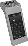
Handheld IO Link Programmers
 |
3-Pole M8 |
4-Pole M8 |
5-Pole M12 |
Configure any of your IO Link devices—from sensors to switches—without a PC, outlet, or separate software. Use these programmers to set parameters, check the quality of runs, clone settings for other devices, and more. Whether you’re setting up a device for the first time or adjusting settings, the easy-to-use touchscreen makes for a smooth experience. Since these programmers are powered by a battery and small enough to carry, you can bring them wherever you need.
As soon as you connect your device, these programmers download its IO Device Description (IODD) file. This means you won’t need to manually input device details, saving you time to jump right into programming. Internal storage keeps IODD files and custom settings on hand for you. If you need extra space, insert a microSD card (not included) into these programmers before turning on the connected device.
Plug devices with M8 or M12 connections directly into the sockets on these programmers. If your device has wire leads, use the included adapter.
Connection Type | Internal Memory Size, GB | Data Connection | Features | Enclosure Rating | Battery Type | Includes | Certification | Each | ||
|---|---|---|---|---|---|---|---|---|---|---|
| A-Code, 3-Pole M8 Plug In A-Code, 4 -Pole M8 Plug In A-Code, 5-Pole M12 Plug In | 16 | Wi-Fi microSD Card | LED Status Indicator | IP30 | Rechargeable | M12 to 4 Hook Adapter (1 1/2 ft. Lg) USB Charging Cord (1 1/2 ft. Lg) | CE Marked | 6457N11 | 000000000 |
Current-Monitoring Relays
 |  |
Screw Terminals with IO Link, Keypad Adjustment | Spring-Clamp Terminals with IO Link, Keypad Adjustment |
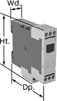
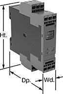
Protect electrical equipment from overcurrent and undercurrent damage—these relays continuously monitor current flow. When current is outside a set range, they trip and cut power to prevent overheating, fire hazards, and stalling. Rated IP20, these relays have recessed terminals that keep fingers and other objects from touching live circuits. Mount them on a 35 mm DIN rail (also known as DIN 3 rail) for fast installation.
Spring-Clamp-Terminal Wire Connection—Relays with spring-clamp terminals connect and disconnect to wire without screws. Because there’s no screw, these connections are less likely to loosen over time, even in high-vibration environments.
IO Link Communication Protocol—Relays with IO link can be programmed, monitored, and reset remotely by connecting them to a programmable logic controller (PLC), human-machine interface (HMI), or computer. If you want to program them locally, they have a keypad.
No. of Terminals | Input Voltage, V DC | Trip Current, amp | Trip Time, sec. | Reset Type | Switching Current @ Voltage | Max. Switching Voltage | Adjustment Mechanism | Ht. | Wd. | Dp. | Digital Display Type | Each | |||||||||||||||||||||||||||||||||||||||||||||||||||||||||||||||||||||||||||||||||||||||
|---|---|---|---|---|---|---|---|---|---|---|---|---|---|---|---|---|---|---|---|---|---|---|---|---|---|---|---|---|---|---|---|---|---|---|---|---|---|---|---|---|---|---|---|---|---|---|---|---|---|---|---|---|---|---|---|---|---|---|---|---|---|---|---|---|---|---|---|---|---|---|---|---|---|---|---|---|---|---|---|---|---|---|---|---|---|---|---|---|---|---|---|---|---|---|---|---|---|---|---|
Screw Terminals with IO Link | |||||||||||||||||||||||||||||||||||||||||||||||||||||||||||||||||||||||||||||||||||||||||||||||||||
1 Circuit Controlled with 1 Off or 1 On—SPDT | |||||||||||||||||||||||||||||||||||||||||||||||||||||||||||||||||||||||||||||||||||||||||||||||||||
| 9 | 24 | 0.05 to 10 | 0 to 999 | Automatic | 3 amp @ 240V AC 1 amp @ 24V DC | 400V AC 250V DC | External Controller, Keypad | 3.6" | 0.9" | 3.4" | LCD | 8123N11 | 0000000 | ||||||||||||||||||||||||||||||||||||||||||||||||||||||||||||||||||||||||||||||||||||||
Spring-Clamp Terminals with IO Link | |||||||||||||||||||||||||||||||||||||||||||||||||||||||||||||||||||||||||||||||||||||||||||||||||||
1 Circuit Controlled with 1 Off or 1 On—SPDT | |||||||||||||||||||||||||||||||||||||||||||||||||||||||||||||||||||||||||||||||||||||||||||||||||||
| 9 | 24 | 0.05 to 10 | 0 to 999 | Automatic | 3 amp @ 240V AC 1 amp @ 24V DC | 400V AC 250V DC | External Controller, Keypad | 3.8" | 0.9" | 3.4" | LCD | 8123N12 | 000000 | ||||||||||||||||||||||||||||||||||||||||||||||||||||||||||||||||||||||||||||||||||||||
Voltage-Monitoring Relays
Monitoring Relays with IO Link
 |
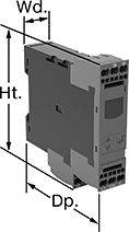
Relays with IO link can be programmed, monitored and reset remotely by connecting them to a programmable logic controller (PLC), human-machine interface (HMI), or computer. If you want to program them locally, they have a keypad.
With Spring-Clamp Terminals—Relays with spring-clamp terminals connect and disconnect to wire without screws. Because there’s no screw, these connections are less likely to loosen over time, even in high-vibration environments.
No. of Terminals | Input Voltage, V DC | Trip Voltage | Trip Time, sec. | Reset Type | Switching Current @ Voltage | Max. Switching Voltage | Adjustment Mechanism | Ht. | Wd. | Dp. | Digital Display Type | Features | Each | ||||||||||||||||||||||||||||||||||||||||||||||||||||||||||||||||||||||||||||||||||||||
|---|---|---|---|---|---|---|---|---|---|---|---|---|---|---|---|---|---|---|---|---|---|---|---|---|---|---|---|---|---|---|---|---|---|---|---|---|---|---|---|---|---|---|---|---|---|---|---|---|---|---|---|---|---|---|---|---|---|---|---|---|---|---|---|---|---|---|---|---|---|---|---|---|---|---|---|---|---|---|---|---|---|---|---|---|---|---|---|---|---|---|---|---|---|---|---|---|---|---|---|
1 Circuit Controlled with 1 Off or 1 On—SPDT | |||||||||||||||||||||||||||||||||||||||||||||||||||||||||||||||||||||||||||||||||||||||||||||||||||
With Screw Terminals | |||||||||||||||||||||||||||||||||||||||||||||||||||||||||||||||||||||||||||||||||||||||||||||||||||
| 9 | 24 | 10V AC to 600V AC, 10V DC to 600V DC | 0 to 999 | Automatic | 3 amp @ 240V AC 1 amp @ 24V DC | 400V AC 250V DC | External Controller, Keypad | 3.6" | 0.9" | 3.6" | LCD | Remote Reset | 8446N105 | 0000000 | |||||||||||||||||||||||||||||||||||||||||||||||||||||||||||||||||||||||||||||||||||||
With Spring-Clamp Terminals | |||||||||||||||||||||||||||||||||||||||||||||||||||||||||||||||||||||||||||||||||||||||||||||||||||
| 9 | 24 | 10V AC to 600V AC, 10V DC to 600V DC | 0 to 999 | Automatic | 3 amp @ 240V AC 1 amp @ 24V DC | 400V AC 250V DC | External Controller, Keypad | 3.8" | 0.9" | 3.6" | LCD | Remote Reset | 8446N106 | 000000 | |||||||||||||||||||||||||||||||||||||||||||||||||||||||||||||||||||||||||||||||||||||
Ground-Fault Monitoring Relays
 |  |
Screw Terminals with IO Link | Spring-Clamp Terminals with IO Link |
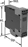
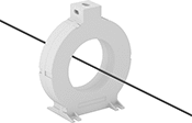
Detect and mitigate ground faults to prevent harm to equipment, circuits, and people. These relays monitor the differential between incoming and outgoing current, also known as residual current. When the balance is off, they trip and cut power to the circuit. These relays are highly sensitive, so you can trust them to de-energize faulty circuits before a minor issue becomes a major one. Rated IP20, they have recessed terminals that keep fingers and other objects from touching live circuits. Mount them on 35 mm DIN rail (also known as DIN 3 rail) for fast installation.
These relays require a current-indicating ring (sold separately) to operate. Choose a ring that is large enough for your lines to pass through. Feed the lines of the circuit through the center of the ring and connect the indicating ring output to the relay.
Spring-Clamp-Terminal Wire Connection—Relays with spring-clamp terminals connect and disconnect to wire without screws. Because they don’t have screws, there’s less of a risk that they will loosen over time, even when they’re under vibration.
IO Link Communication Protocol—Relays with IO link can be programmed, monitored, and reset remotely by connecting them to a programmable logic controller (PLC), human-machine interface (HMI), or computer. If you want to program them locally, they have a keypad.
No. of Terminals | Input Voltage, V DC | Trip Current, amp | Trip Time, sec. | Switching Current @ Voltage | Max. Switching Voltage | Adjustment Mechanism | Ht. | Wd. | Dp. | Features | Each | ||||||||||||||||||||||||||||||||||||||||||||||||||||||||||||||||||||||||||||||||||||||||
|---|---|---|---|---|---|---|---|---|---|---|---|---|---|---|---|---|---|---|---|---|---|---|---|---|---|---|---|---|---|---|---|---|---|---|---|---|---|---|---|---|---|---|---|---|---|---|---|---|---|---|---|---|---|---|---|---|---|---|---|---|---|---|---|---|---|---|---|---|---|---|---|---|---|---|---|---|---|---|---|---|---|---|---|---|---|---|---|---|---|---|---|---|---|---|---|---|---|---|---|
Screw Terminals with IO Link | |||||||||||||||||||||||||||||||||||||||||||||||||||||||||||||||||||||||||||||||||||||||||||||||||||
2 Circuits Controlled with 2 Off or 2 On—DPDT | |||||||||||||||||||||||||||||||||||||||||||||||||||||||||||||||||||||||||||||||||||||||||||||||||||
| 12 | 24 | 0.03 to 40 | 0 to 999 | 3 amp @ 240V AC 1 amp @ 24V DC | 400V AC 250V DC | External Controller, Keypad | 4" | 0.9" | 3.6" | Remote Reset | 8121N109 | 0000000 | |||||||||||||||||||||||||||||||||||||||||||||||||||||||||||||||||||||||||||||||||||||||
Spring-Clamp Terminals with IO Link | |||||||||||||||||||||||||||||||||||||||||||||||||||||||||||||||||||||||||||||||||||||||||||||||||||
2 Circuits Controlled with 2 Off or 2 On—DPDT | |||||||||||||||||||||||||||||||||||||||||||||||||||||||||||||||||||||||||||||||||||||||||||||||||||
| 12 | 24 | 0.03 to 40 | 0 to 999 | 3 amp @ 240V AC 1 amp @ 24V DC | 400V AC 250V DC | External Controller, Keypad | 4.1" | 0.9" | 3.6" | Remote Reset | 8121N111 | 000000 | |||||||||||||||||||||||||||||||||||||||||||||||||||||||||||||||||||||||||||||||||||||||
Multifunction Monitoring Relays
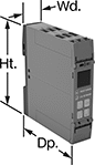 |
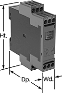
Monitor phase, voltage, and frequency at the same time to protect motors, generators, and other three-phase circuits from burning out or overheating. They'll switch the circuit off if they detect voltage or frequencies outside of the set range or phase loss, imbalance, or reversal. Rated IP20, they have recessed terminals that keep fingers and other objects from touching live circuits. Mount them on a 35 mm DIN rail (also known as DIN 3 rail) for fast installation.
These relays use IO Link, so they can be programmed, monitored, and reset remotely by connecting them to a programmable logic controller (PLC), human-machine interface (HMI), or computer. If you want to program them locally, they have a keypad.
Spring-Clamp-Terminal Wire Connection—Relays with spring-clamp terminals connect and disconnect to wire without screws. Because there’s no screw, these connections are less likely to loosen over time, even in high-vibration environments.
No. of Terminals | Input Voltage, V DC | Trip Voltage, V AC | Input Freq., Hz | Trip Freq., Hz | Trip Time, sec. | Reset Type | Switching Current @ Voltage | Max. Switching Voltage | Adjustment Mechanism | Ht. | Wd. | Dp. | Each | ||||||||||||||||||||||||||||||||||||||||||||||||||||||||||||||||||||||||||||||||||||||
|---|---|---|---|---|---|---|---|---|---|---|---|---|---|---|---|---|---|---|---|---|---|---|---|---|---|---|---|---|---|---|---|---|---|---|---|---|---|---|---|---|---|---|---|---|---|---|---|---|---|---|---|---|---|---|---|---|---|---|---|---|---|---|---|---|---|---|---|---|---|---|---|---|---|---|---|---|---|---|---|---|---|---|---|---|---|---|---|---|---|---|---|---|---|---|---|---|---|---|---|
1 Circuit Controlled with 1 Off or 1 On—SPDT | |||||||||||||||||||||||||||||||||||||||||||||||||||||||||||||||||||||||||||||||||||||||||||||||||||
Screw Terminals with IO Link | |||||||||||||||||||||||||||||||||||||||||||||||||||||||||||||||||||||||||||||||||||||||||||||||||||
| 12 | 24 | 90 to 760 | 50, 60 | 15 to 70 | 0.1 to 30 | Automatic | 3 amp @ 240V AC 1 amp @ 24V DC | 400V AC 250V DC | External Controller, Keypad | 3.9" | 0.9" | 3.6" | 8449N12 | 0000000 | |||||||||||||||||||||||||||||||||||||||||||||||||||||||||||||||||||||||||||||||||||||
Spring-Clamp Terminals with IO Link | |||||||||||||||||||||||||||||||||||||||||||||||||||||||||||||||||||||||||||||||||||||||||||||||||||
| 12 | 24 | 90 to 760 | 50, 60 | 15 to 70 | 0.1 to 30 | Automatic | 3 amp @ 240V AC 1 amp @ 24V DC | 400V AC 250V DC | External Controller, Keypad | 3.9" | 0.9" | 3.6" | 8449N11 | 000000 | |||||||||||||||||||||||||||||||||||||||||||||||||||||||||||||||||||||||||||||||||||||
