


Filter by
Body Material


For Flange Class
Mounting Position
Valve Type
Pressure Class
Maximum Temperature
Actuation
Maximum Pressure @ Temperature
Connects To
Export Control Classification Number (ECCN)
U.S.–Mexico–Canada Agreement (USMCA) Qualifying
REACH
DFARS Specialty Metals
Specifications Met
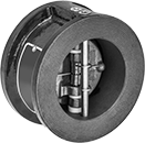
Flange-Mount Check Valves
Cast Iron Body
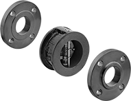 |  |
Shown with Flanges (Not Included) |
Flow Coefficient (Cv)—Flow coefficient (Cv) is the amount of water (in gallons per minute) at 60° F that will flow through a fully open valve with a difference of 1 psi between the inlet and the outlet.
Pipe Size | Flow Coefficient (Cv) | Max. Pressure @ Temp. | Min. Opening Pressure, psi | Temp. Range, ° F | End-to-End Lg. | Mounting Position | For Flange Class | For Use With | Disc Material | Seal Material | Each | |||
|---|---|---|---|---|---|---|---|---|---|---|---|---|---|---|
Flanged × Flanged | ||||||||||||||
| 2 | 60 | 200 psi @ 70° F | 1.25 | -20 to 250 | 2 1/8" | Horizontal, Vertical | 125 | Air, Argon, Helium, Krypton, Neon, Water, Xenon | Bronze | Buna-N | 5023K31 | 000000 | ||
| 2 1/2 | 100 | 200 psi @ 70° F | 1.25 | -20 to 250 | 2 1/8" | Horizontal, Vertical | 125 | Air, Argon, Helium, Krypton, Neon, Water, Xenon | Bronze | Buna-N | 5023K32 | 00000 | ||
| 3 | 170 | 200 psi @ 70° F | 1.25 | -20 to 250 | 2 1/4" | Horizontal, Vertical | 125 | Air, Argon, Helium, Krypton, Neon, Water, Xenon | Bronze | Buna-N | 5023K33 | 000000 | ||
| 4 | 340 | 200 psi @ 70° F | 1.25 | -20 to 250 | 2 1/2" | Horizontal, Vertical | 125 | Air, Argon, Helium, Krypton, Neon, Water, Xenon | Bronze | Buna-N | 5023K44 | 000000 | ||
| 5 | 520 | 200 psi @ 70° F | 1.25 | -20 to 250 | 2 3/4" | Horizontal, Vertical | 125 | Air, Argon, Helium, Krypton, Neon, Water, Xenon | Bronze | Buna-N | 5023K45 | 000000 | ||
| 6 | 850 | 200 psi @ 70° F | 1.25 | -20 to 250 | 3" | Horizontal, Vertical | 125 | Air, Argon, Helium, Krypton, Neon, Water, Xenon | Bronze | Buna-N | 5023K46 | 000000 | ||
| 8 | 1,600 | 200 psi @ 70° F | 1.25 | -20 to 250 | 3 3/4" | Horizontal, Vertical | 125 | Air, Argon, Helium, Krypton, Neon, Water, Xenon | Bronze | Buna-N | 5023K47 | 000000 | ||
| 10 | 2,400 | 200 psi @ 70° F | 1.25 | -20 to 250 | 4 1/4" | Horizontal, Vertical | 125 | Air, Argon, Helium, Krypton, Neon, Water, Xenon | Bronze | Buna-N | 5023K51 | 000000 | ||
Flanged Check Valves
Cast Iron Body
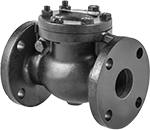 |
Flow Coefficient (Cv)—Flow coefficient (Cv) is the amount of water (in gallons per minute) at 60° F that will flow through a fully open valve with a difference of 1 psi between the inlet and the outlet.
Pipe Size | Flow Coefficient (Cv) | Max. Pressure @ Temp. | Max. Steam Pressure @ Temp. | Min. Opening Pressure, psi | Temp. Range, ° F | End-to-End Lg. | Mounting Position | Flange OD | No. of Bolt Holes | Bolt Hole Size | Bolt Circle Dia. | Bolts Included | Includes | Specs. Met | For Use With | Disc Material | Seal Material | Each | |||
|---|---|---|---|---|---|---|---|---|---|---|---|---|---|---|---|---|---|---|---|---|---|
Flanged × Flanged—Pressure Class 125 | |||||||||||||||||||||
| 2 | 110 | 200 psi @ 70° F | 125 psi @ 353° F | 1 | -20 to 405 | 8" | Horizontal | 6" | 4 | 5/8" | 4 3/4" | No | Removable Cap | ASTM A126 Class B, MSS SP-71 | Air, Steam, Water | Bronze | Bronze | 8200T11 | 0000000 | ||
| 2 1/2 | 193 | 200 psi @ 70° F | 125 psi @ 353° F | 1 | -20 to 405 | 8 1/2" | Horizontal | 7" | 4 | 3/4" | 5 1/2" | No | Removable Cap | ASTM A126 Class B, MSS SP-71 | Air, Steam, Water | Bronze | Bronze | 8200T12 | 000000 | ||
| 3 | 292 | 200 psi @ 70° F | 125 psi @ 353° F | 1 | -20 to 405 | 9 1/2" | Horizontal | 7 1/2" | 4 | 3/4" | 6" | No | Removable Cap | ASTM A126 Class B, MSS SP-71 | Air, Steam, Water | Bronze | Bronze | 8200T13 | 000000 | ||
| 4 | 468 | 200 psi @ 70° F | 125 psi @ 353° F | 1 | -20 to 405 | 11 1/2" | Horizontal | 9" | 8 | 3/4" | 7 1/2" | No | Removable Cap | ASTM A126 Class B, MSS SP-71 | Air, Steam, Water | Bronze | Bronze | 8200T14 | 000000 | ||
| 5 | 735 | 200 psi @ 70° F | 125 psi @ 353° F | 1 | -20 to 405 | 13" | Horizontal | 10" | 8 | 3/4" | 8 1/2" | No | Removable Cap | ASTM A126 Class B, MSS SP-71 | Air, Steam, Water | Iron | Bronze | 8200T15 | 00000000 | ||
| 6 | 1,060 | 200 psi @ 70° F | 125 psi @ 353° F | 1 | -20 to 405 | 14" | Horizontal | 11" | 8 | 7/8" | 9 1/2" | No | Removable Cap | ASTM A126 Class B, MSS SP-71 | Air, Steam, Water | Iron | Bronze | 8200T16 | 00000000 | ||
| 8 | 1,880 | 200 psi @ 70° F | 125 psi @ 353° F | 1 | -20 to 405 | 19 1/2" | Horizontal | 13 1/2" | 8 | 3/4" | 11 3/4" | No | Removable Cap | ASTM A126 Class B, MSS SP-71 | Air, Steam, Water | Iron | Bronze | 8200T17 | 00000000 | ||
Arresters for Flammable Vapors
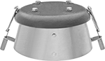 |
Minimize fire hazard from flammable vapors. Mount an arrester to your vent pipe to stop flames from traveling back into your tank. If the ambient temperature reaches 165° F, the fusible links melt, and the cover closes to block flames from the arrester.
Replacement Fusible Links—To reuse the arrester, replace the fusible links (sold separately).
