


Filter by
Maximum Discharge Pressure
Power Source
Maximum Feet of Head
Pump Type
Housing Material
Priming Type
U.S.–Mexico–Canada Agreement (USMCA) Qualifying
DFARS Specialty Metals
Export Control Classification Number (ECCN)
REACH
Air-Powered Constant-Flow-Rate Piston Pumps
 |
Commonly called piston pumps, these are often used in high-pressure applications, such as hydrostatic testing of pipelines, tanks, and valves. Flow and outlet liquid pressure can be controlled by varying the air pressure. To calculate discharge liquid pressure, multiply the air pressure by the ratio shown in the table. Pumps are self-priming, which means they create a suction force to draw liquid upward to fill the pump chamber.
Note: Pumps must be filled with liquid before use. They need a constant flow of liquid and cannot run dry.
Flow Rate, gpm | Air Pressure, psi | Overall | |||||||||||||||
|---|---|---|---|---|---|---|---|---|---|---|---|---|---|---|---|---|---|
@ 0 psi | @ 3,000 psi | Max. ft. of Head, ft. | Max. Discharge Pressure, psi | Max. Viscosity, cP | Min. | Max. | Air Consumption, scfm | Air Connection (NPT) | Intake Pipe Connection (NPT) | Discharge Pipe Connection (NPT) | Lg. | Wd. | Ht. | Each | |||
86:1 Discharge Liquid to Inlet Air Pressure Ratio | |||||||||||||||||
| 0.19 | 0.17 | 28,764 | 12,470 | 100 | 15 | 145 | 20 | 1/4 Female | 3/8 Female | 1/4 Female | 4 5/8" | 4" | 9" | 6770K43 | 000000000 | ||
28:1 Discharge Liquid to Inlet Air Pressure Ratio | |||||||||||||||||
| 0.58 | 0.13 | 9,365 | 4,060 | 100 | 15 | 145 | 20 | 1/4 Female | 3/8 Female | 1/4 Female | 4 5/8" | 4" | 9" | 6770K41 | 00000000 | ||
11:1 Discharge Liquid to Inlet Air Pressure Ratio | |||||||||||||||||
| 4.76 | — | 3,679 | 1,595 | 100 | 15 | 145 | 45 | 1/2 Female | 1 Female | 1/2 Female | 10 3/4" | 9 1/2" | 10 3/8" | 6770K28 | 00000000 | ||
High-Pressure Constant-Flow-Rate Pumps without Motor for Pressure Washing
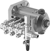 |
Also known as plunger pumps, these can provide pressures up to 3,000 psi. Use them for washdowns, drain jetting, and other pressurized water-spraying applications. Connect them directly to an electric motor to alter the pump speed. Pumps are gravity fed and require an elevated liquid source to fully fill the pump before turning on. Do not run dry or use with solids.
Intake | Discharge | Overall | |||||||||||||||
|---|---|---|---|---|---|---|---|---|---|---|---|---|---|---|---|---|---|
Max. Flow Rate, gpm | Max. Pressure, psi | Temp. Range, ° F | Req. Power, hp | For Motor Frame Size | Pipe Size | Thread Type | Gender | Pipe Size | Thread Type | Gender | Lg. | Wd. | Ht. | For Shaft Dia. | Each | ||
| 2 | 2,000 | -20 to 160 | 2.7 | NEMA 56C | 3/8 | NPT | Female | 3/8 | NPT | Female | 8 1/4" | 8 5/8" | 6 1/2" | 5/8" | 82415K91 | 0000000 | |
| 3 | 3,000 | -20 to 140 | 6 1/5 | NEMA 182TC, NEMA 184TC | 1/2 | NPT | Female | 3/8 | NPT | Female | 9 1/2" | 9 1/4" | 7 1/8" | 1 1/8" | 82415K92 | 000000 | |
| 4 | 2,000 | -20 to 140 | 5 1/2 | NEMA 182TC, NEMA 184TC | 1/2 | NPT | Female | 3/8 | NPT | Female | 9 1/2" | 9 1/4" | 7 1/8" | 1 1/8" | 82415K93 | 000000 | |
