Filter by

Height
Weight Capacity per Pair
Weight Capacity
Adjustment Mechanism
Application
Holding Capacity
Support Type
Wheel Configuration


Mobility
Export Control Classification Number (ECCN)
DFARS Specialty Metals
Weight Capacity @ Maximum Height
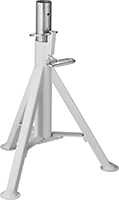
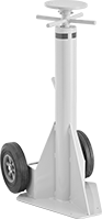
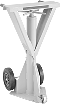
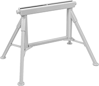
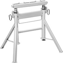
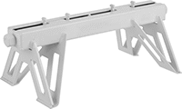
Jack Stands—Not for Lifting
 | 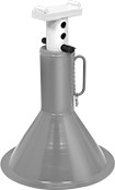 | 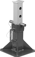 |
Style A | Style B | Style C |
After raising a load, add these steel stands for support.
Note: Do not raise or lower stands while under load. Always use stands in pairs and on a hard, flat surface.
Warning: Never use to support people or loads over people.
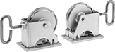
Locking-Handle Adjustment—Locking handles lock the ratchet bar in place to support the load.
Locking-Pin Adjustment—Locking pins are inserted through the riser to lock the bar in place.
Saddle | Base | |||||||||||
|---|---|---|---|---|---|---|---|---|---|---|---|---|
Style | Wt. Cap. per Pair | Ht. | Ht. Adjustment Increments | Lg. | Wd. | Dia. | Lg. | Wd. | Pair | |||
Locking-Handle Adjustment | ||||||||||||
| A | 6 ton/12,000 lb. | 12" to 17 3/4" | 9/16" | 1" | 3 1/2" | — | 7 1/2" | 8 1/4" | 8059T31 | 0000000 | ||
| A | 12 ton/24,000 lb. | 15 5/8" to 23 3/4" | 11/16" | 1 1/4" | 4 1/4" | — | 10 3/8" | 11 5/8" | 8059T32 | 000000 | ||
Locking-Pin Adjustment | ||||||||||||
| B | 12 ton/24,000 lb. | 19" to 29 1/2" | 1 1/2" | 3" | 6" | 15 7/8" | — | — | 8059T33 | 000000 | ||
| C | 44 ton/88,000 lb. | 13 7/8" to 19 7/8" | 3" | 3" | 3 3/4" | — | 11" | 11" | 8059T35 | 000000 | ||
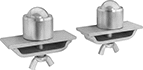
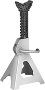
Screw Jack Stands
Stationary
 |  |
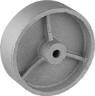
Replacement Grip |
Saddle | ||||||||||
|---|---|---|---|---|---|---|---|---|---|---|
Wt. Cap. | Holding Cap. | Ht. | Max. Lift | Lg. | Wd. | Base Dia. | Each | |||
| 2 1/2 ton/5,000 lb. | 25 ton/50,000 lb. | 44" to 51" | 7" | 5" | 5" | 14" | 8817T61 | 0000000 | ||
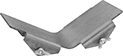
Rolling
 |  | |
Two Axle-Mounted Wheels | Three Axle-Mounted Wheels | Replacement Grip |
 |  |  |
Replacement Handle | Replacement Saddle | Replacement Wheel Kit |
 | ||
Replacement Wheel |
Saddle | Base | ||||||||||||||
|---|---|---|---|---|---|---|---|---|---|---|---|---|---|---|---|
Wt. Cap. | Holding Cap. | Ht. | Max. Lift | Dia. | Lg. | Wd. | Lg. | Wd. | Handle Lg. | Wheel Material | Features | Each | |||
Two Axle-Mounted Wheels | |||||||||||||||
| 20 ton/40,000 lb. | 50 ton/100,000 lb. | 39" to 51" | 12" | 8" | — | — | 16" | 17 5/8" | 20" | Rubber | Removable Handle | 8817T62 | 0000000 | ||
Three Axle-Mounted Wheels | |||||||||||||||
| 20 ton/40,000 lb. | 50 ton/100,000 lb. | 40" to 51" | 11" | — | 24" | 6" | 16" | 17 5/8" | 20" | Rubber, Steel | Removable Handle | 8817T74 | 000000 | ||
Jack Posts
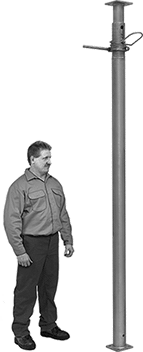 |
Support beams and joists.
Locking-Pin Adjustment—To adjust the height of locking-pin jack posts, extend the post to the approximate height needed and insert the locking pin through the hole to secure. Then turn the threaded handle counterclockwise to raise it up to 6" for more precise height adjustments.
Locking-Ring Adjustment—To adjust the height of locking-ring jack posts, slide the safety lock into the notch to secure at the approximate height needed. Then turn the 10" long handle for final height adjustments.
Ht. | Wt. Cap. | Base | Top Plate | |||||||||||||
|---|---|---|---|---|---|---|---|---|---|---|---|---|---|---|---|---|
Min. | Max. | @ Min. Ht. | @ Max. Ht. | Material | Wd. | Dp. | Wd. | Dp. | Mounting Hole Dia. (No. of) | Mounting Fasteners Included | Ctr.-to-Ctr. Adjustments | Handle Lg. | Each | |||
Locking-Pin Adjustment | ||||||||||||||||
| 78" | 138" | 6,400 lb. @ 78" | 3,800 lb. @ 138" | Steel | 4 3/4" | 4 3/4" | 4 3/4" | 4 3/4" | 9/16" (8) | No | 6" | — | 2929T15 | 0000000 | ||
| 120" | 216" | 9,300 lb. @ 120" | 2,700 lb. @ 216" | Steel | 4 3/4" | 4 3/4" | 4 3/4" | 4 3/4" | 9/16" (8) | No | 6" | — | 2929T16 | 000000 | ||
Locking-Ring Adjustment | ||||||||||||||||
| 16" | 24" | 18,000 lb. @ 16" | 18,000 lb. @ 24" | Steel | 4" | 4" | 4" | 4" | 3/8" (4), 5/8" (4) | No | 4" | 10" | 2946T5 | 000000 | ||
| 25" | 41" | 18,000 lb. @ 25" | 17,000 lb. @ 41" | Steel | 4" | 4" | 4" | 4" | 3/8" (4), 5/8" (4) | No | 4" | 10" | 2946T4 | 000000 | ||
| 40" | 64" | 18,000 lb. @ 40" | 17,000 lb. @ 64" | Steel | 4" | 4" | 4" | 4" | 3/8" (4), 5/8" (4) | No | 4" | 10" | 2946T3 | 000000 | ||
| 68" | 100" | 17,000 lb. @ 68" | 14,000 lb. @ 100" | Steel | 4" | 4" | 4" | 4" | 3/8" (4), 5/8" (4) | No | 4" | 10" | 2946T1 | 000000 | ||
Bench-Top Hand-Crank Stationary Lift Tables
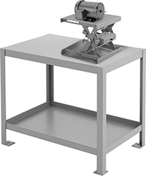 |  |
Base | ||||||||||||
|---|---|---|---|---|---|---|---|---|---|---|---|---|
Wt. Cap., lb. | Lg. | Wd. | Ht. | Lg. | Wd. | Elevation per Stroke | Color | Includes | Each | |||
Powder-Coated Steel | ||||||||||||
| 660 | 20" | 20" | 6 1/2" to 14" | 20" | 20" | 1/4" | Orange | Ratchet Wrench | 9916N101 | 0000000 | ||
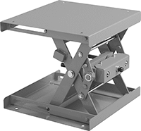
Laboratory Jacks
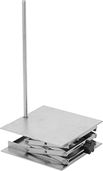 | 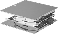 |
Laboratory Jacks | Laboratory Jack Support Rods | ||||||||
|---|---|---|---|---|---|---|---|---|---|
Head | |||||||||
Max. Load Cap., lb. | Ht. | Lg. | Wd. | Material | Each | Each | |||
| 100 | 2 1/2" to 5" | 3" | 3" | Stainless Steel | 9967T42 | 0000000 | ——— | 0 | |
| 100 | 2 1/2" to 5" | 4" | 4" | Stainless Steel | 9967T51 | 000000 | ——— | 0 | |
| 133 | 3" to 9 3/4" | 6" | 6" | Stainless Steel | 9967T43 | 000000 | 9967T5 | 000000 | |
| 227 | 3 1/2" to 13" | 8" | 8" | Stainless Steel | 9967T44 | 000000 | 9967T5 | 00000 | |
| 247 | 3 1/2" to 13" | 10" | 10" | Stainless Steel | 9967T55 | 000000 | 9967T5 | 00000 | |
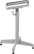
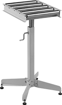
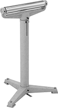
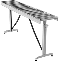
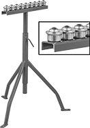
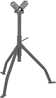
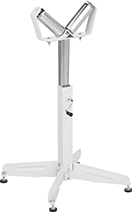
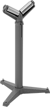
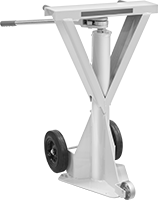
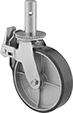
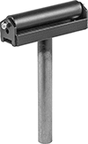
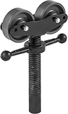
Material Support Stands
 | 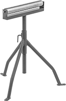 |  |  |
Style A | Style B | Style C | Style D |
 |  |  |  |
Style E | Style F | Style G |
Roller | Ball | Base | ||||||||||||||||||
|---|---|---|---|---|---|---|---|---|---|---|---|---|---|---|---|---|---|---|---|---|
Style | Between Frame Wd. | Ht. | Wt. Cap., lb. | Top Rail Wd. | Dia. | Spacing | Material | Dia. | Spacing | Material | Lg. | Wd. | Material | Mounting Fasteners Included | Mounting Hole Dia. | Features | Each | |||
Roller Support | ||||||||||||||||||||
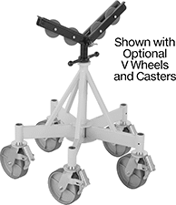
Bipod Stand | ||||||||||||||||||||
| A | 13" | 28" to 42" | 250 | — | 1 7/8" | — | Steel | — | — | — | 18" | 15 1/2" | Steel | — | — | Folding Legs, Nonskid Feet | 5771K51 | 0000000 | ||
Tripod Stand | ||||||||||||||||||||
| B | 16" | 23" to 39" | 300 | — | 2" | — | Steel | — | — | — | 21 3/8" | 24 1/4" | Steel | No | 3/8" | — | 2756T1 | 000000 | ||
| B | 16" | 28" to 50" | 300 | — | 2" | — | Steel | — | — | — | 21 3/8" | 24 1/4" | Steel | No | 3/8" | — | 2756T2 | 000000 | ||
Pedestal Stand | ||||||||||||||||||||
| C | 16" | 22" to 32" | 500 | — | 2" | — | Galvanized Steel | — | — | — | 17" | 16" | Steel | — | — | Leveling Feet | 5750K25 | 000000 | ||
| C | 16" | 27 1/4" to 44 1/4" | 350 | — | 2" | — | Galvanized Steel | — | — | — | 18" | 18" | Steel | — | — | Leveling Feet | 5750K15 | 000000 | ||
| C | 16" | 28" to 45 1/2" | 500 | — | 2" | — | Galvanized Steel | — | — | — | 17" | 16" | Steel | — | — | Leveling Feet | 5750K26 | 000000 | ||
| D | 13" | 26 1/2" to 43 1/2" | 500 | — | 1 3/8" | 4" | Galvanized Steel | — | — | — | 18" | 15" | Steel | — | — | Leveling Feet | 5760K68 | 000000 | ||
| E | 14" | 24 1/2" to 39 1/2" | 1,760 | — | 2" | — | Chrome-Plated Steel | — | — | — | 19 1/4" | 19 1/4" | Steel | — | — | — | 5750K13 | 000000 | ||
| E | 14" | 27" to 42 1/2" | 1,760 | — | 2" | — | Chrome-Plated Steel | — | — | — | 19 1/4" | 19 1/4" | Steel | — | — | — | 5750K14 | 000000 | ||
| E | 14" | 29" to 39" | 1,760 | — | 2" | — | Chrome-Plated Steel | — | — | — | 19 1/4" | 19 1/4" | Steel | — | — | Gas Charged Cylinder | 5750K11 | 000000 | ||
| E | 14" | 33" to 43" | 1,760 | — | 2" | — | Chrome-Plated Steel | — | — | — | 19 1/4" | 19 1/4" | Steel | — | — | Gas Charged Cylinder | 5750K12 | 000000 | ||
Table Stand | ||||||||||||||||||||
| F | 13" | 26 1/2" to 43 1/2" | 500 | — | 1 3/8" | 4" | Galvanized Steel | — | — | — | 66" | 15" | Steel | — | — | Folding Legs, Leveling Feet | 5760K65 | 000000 | ||
Ball-Transfer Support | ||||||||||||||||||||
Tripod Stand | ||||||||||||||||||||
| G | — | 28" to 48" | 200 | 18" | — | — | — | 1" | 2" | Steel | 21 3/8" | 24 1/4" | Steel | No | 3/8" | — | 5904K4 | 000000 | ||
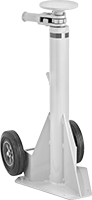
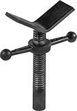
Material Support Stands for Pipe
 |  |  |
Style A | Style B | Style C |
Roller | Base | ||||||||||||||
|---|---|---|---|---|---|---|---|---|---|---|---|---|---|---|---|
Style | For Max. OD | Ht. | Wt. Cap., lb. | Dia. | Material | Lg. | Wd. | Material | Mounting Fasteners Included | Mounting Hole Dia. | Features | Each | |||
Roller Support, V-Style Support | |||||||||||||||
Tripod Stand | |||||||||||||||
| A | 4" | 25 3/4" to 38" | 400 | 2" | Steel | 21 3/8" | 24 1/4" | Steel | No | 3/8" | — | 5006T71 | 0000000 | ||
Pedestal Stand | |||||||||||||||
| B | 17" | 22" to 32" | 500 | 2" | Steel | 17" | 17" | Steel | — | — | — | 5006T101 | 000000 | ||
| B | 17" | 26 1/2" to 43 1/2" | 500 | 2" | Steel | 17" | 17" | Steel | — | — | — | 5006T102 | 000000 | ||
| C | 19 1/4" | 23" to 38 1/2" | 1,750 | 2" | Steel | 19 1/4" | 19 1/4" | Steel | No | 3/8" | — | 5006T105 | 000000 | ||
| C | 19 1/4" | 26" to 36" | 1,750 | 2" | Steel | 19 1/4" | 19 1/4" | Steel | No | 3/8" | Gas Charged Cylinder | 5006T103 | 000000 | ||
| C | 19 1/4" | 27" to 42" | 1,750 | 2" | Steel | 19 1/4" | 19 1/4" | Steel | No | 3/8" | — | 5006T106 | 000000 | ||
| C | 19 1/4" | 33" to 43" | 1,750 | 2" | Steel | 19 1/4" | 19 1/4" | Steel | No | 3/8" | Gas Charged Cylinder | 5006T104 | 000000 | ||
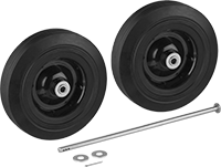
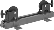
Ratchet Jack Stands
Rolling
 |  | |
Two Axle-Mounted Wheels | Three Axle-Mounted Wheels | Replacement Grip |
| | |
Replacement Handle | Replacement Saddle | Replacement Wheel Kit |
| ||
Replacement Wheel |
Saddle | Base | ||||||||||||||
|---|---|---|---|---|---|---|---|---|---|---|---|---|---|---|---|
Wt. Cap. | Holding Cap. | Ht. | Max. Lift | Dia. | Lg. | Wd. | Lg. | Wd. | Handle Lg. | Wheel Material | Features | Each | |||
Two Axle-Mounted Wheels | |||||||||||||||
| 20 ton/40,000 lb. | 50 ton/100,000 lb. | 39" to 51" | 12" | 8" | — | — | 16" | 17 5/8" | 20" | Rubber | Removable Handle | 8817T63 | 0000000 | ||
Three Axle-Mounted Wheels | |||||||||||||||
| 20 ton/40,000 lb. | 50 ton/100,000 lb. | 40" to 51" | 11 1/2" | — | 24" | 6" | 16" | 17 5/8" | 20" | Rubber, Steel | Removable Handle | 8817T67 | 000000 | ||
Reel Jacks
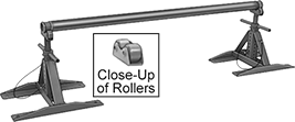 |
Two Jacks Shown with Spindle (All Sold Separately) |
Speed up dispensing from your reels. Use a pair of these adjustable-height, heavy duty jacks to lift and support each end of a spindle (sold separately). A screw mechanism adjusts the height of the jacks. Rollers on the top of the jacks allow the spindle to spin freely as you wind or dispense rope, wire, hose, and chain.
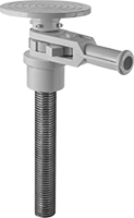
Leveling Micrometer Heads
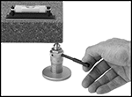 | 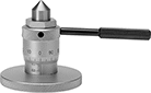 |
Precisely level heavy machines, surface plates, and other devices when accuracy is crucial. Turn the handle to adjust their height, even when under a machine.
Plain Thimble—Plain thimbles turn freely without friction or a stopping device and rely on operator feel for accurate measurements.
Overall | |||||||||||||||
|---|---|---|---|---|---|---|---|---|---|---|---|---|---|---|---|
Distance Measured Range, mm | Measuring Increments, mm | Point Angle | Spindle Face Material | Wt. Cap., lb. | Wd. | Ht. | Base Dia. | Handle Lg. | Features | Mfr. | Mfr. Model No. | Each | |||
Plain Thimble—Rotating Spindle | |||||||||||||||
| 60 to 75 | 0.01 | 90° | Steel | 850 | 4 19/32" | 2 3/8" | 2 17/32" | 3 11/32" | Handle | Mitutoyo | 7850 | 8614N11 | 0000000 | ||
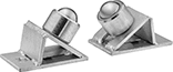
Material Support Stands for Large-Size Pipe
V-Style Support
 |
V-style supports have wide angled arms that support pipe up to 36" diameter. Leveling feet provide stability.
For OD | Arm | Base | |||||||||||
|---|---|---|---|---|---|---|---|---|---|---|---|---|---|
Min. | Max. | Ht. | Wt. Cap., lb. | Lg. | Wd. | Lg. | Wd. | Material | Features | Each | |||
5-Leg Stand | |||||||||||||
| 4" | 36" | 24" to 36" | 5,000 | 12" | 4 5/8" | 32" | 32" | Steel | Leveling Feet | 5006T075 | 0000000 | ||
Wheel Support
 |
Tabletop Stand—Place tabletop stands on a work surface to position pipe while machining. All position pipe parallel to the frame.
For OD | Dia. | Base | |||||||||||
|---|---|---|---|---|---|---|---|---|---|---|---|---|---|
Min. | Max. | Ht. | Wt. Cap., lb. | Wheel | Axle | No. of Wheels Included | Lg. | Wd. | Material | Each | |||
Tabletop Stand | |||||||||||||
| 1/2" | 48" | 6 3/4" | 2,500 | 3 3/4" | 3/8" | 2 | 22" | 7" | Steel | 2683T16 | 0000000 | ||
Flexible-Leg Tripods
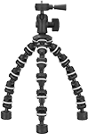 |
Bend and wrap the legs around almost anything while keeping a level mounting surface. Rubber rings around each section prevent slipping. These tripods can also be used like a traditional tripod.
Max. Load Cap., lb. | Ht. | Head Dia. | Leg Dia. | Material | Color | Mount Type | Thread Size | Each | ||
|---|---|---|---|---|---|---|---|---|---|---|
| 5 | 3 1/2" to 10" | 2" | 2" | Plastic | Black | Threaded Stud | 1/4"-20 | 1050A12 | 000000 |
Build-Your-Own Material Support Stands
Supports
 |  | | |
Roller Support | Ball-Transfer Support | Wheel Support |
For OD | Roller | ||||||||||||
|---|---|---|---|---|---|---|---|---|---|---|---|---|---|
Min. | Max. | Between Frame Wd. | Wt. Cap., lb. | Ball Dia. | Dia. | Material | Wheel Dia. | Material | Each | ||||
Roller Support | |||||||||||||
| 1/8" | 18" | 18" | 2,000 | — | 2" | Steel | — | Steel | 2683T214 | 0000000 | |||
Pair | |||||||||||||
Ball-Transfer Support | |||||||||||||
| 1/2" | 36" | — | 3,000 | 1 1/2" | — | — | — | Stainless Steel | 2683T213 | 000000 | |||
Wheel Support | |||||||||||||
| 2" | 36" | — | 5,000 | — | — | — | 4" | Steel | 2683T211 | 000000 | |||
| 2" | 36" | — | 5,000 | — | — | — | 4" | Stainless Steel | 2683T212 | 000000 | |||
Build-Your-Own Tripod Material Support Stands
Supports
 |  |  | |
Tripod Stand Roller Support | Tripod Stand V-Style Support | Tripod Stand Wheel Support |
For OD | Roller | Arm | |||||||||||||
|---|---|---|---|---|---|---|---|---|---|---|---|---|---|---|---|
Min. | Max. | Between Frame Wd. | Wt. Cap., lb. | Dia. | Material | Lg. | Wd. | Wheel Dia. | No. of Wheels Included | Material | Includes | Each | |||
Tripod Stand | |||||||||||||||
Roller Support | |||||||||||||||
| 1/8" | 10" | 10" | 550 | 2" | Steel | — | — | — | — | Steel | — | 8732T223 | 0000000 | ||
V-Style Support | |||||||||||||||
| 1/8" | 12" | — | 2,500 | — | — | 4" | 3" | — | — | Steel | — | 8732T221 | 00000 | ||
| 1/8" | 12" | — | 2,500 | — | — | 4" | 3" | — | — | Steel | V-Style Attachment | 8732T131 | 000000 | ||
Wheel Support | |||||||||||||||
| 1/8" | 12" | — | 1,000 | — | — | — | — | 4" | 2 | Phenolic | — | 8732T224 | 000000 | ||
| 3/8" | 12" | — | 550 | — | — | — | — | 4" | 2 | Stainless Steel | — | 8732T222 | 000000 | ||
| 3/8" | 12" | — | 2,000 | — | — | — | — | 4" | 2 | Aluminum | — | 8732T232 | 000000 | ||