


Filter by
Adjustment Movement
Component
RoHS
DFARS Specialty Metals
Export Control Classification Number (ECCN)
Attaching End Mounting Pattern Compatibility
Performance
Keyboard Trays
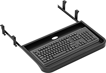 | 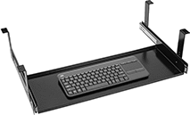 |
Style A | Style B |
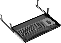 | 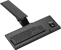 |
Style C | Style D |
Style | Adjustment Movement | Material | Ht. | Wd. | Dp. | Mounting Hardware Included | Each | |||
|---|---|---|---|---|---|---|---|---|---|---|
Trays | ||||||||||
| A | In and Out | Plastic | 1 3/8" | 20 1/2" | 12" | Yes | 13085T22 | 000000 | ||
| B | In and Out | Steel | 2" | 24" | 15 3/4" | Yes | 13085T65 | 00000 | ||
Trays with Padded Wrist Rest and Space for Mouse Pad | ||||||||||
| C | In and Out, Up and Down | Steel | 7 1/4" | 33 1/8" | 20" | Yes | 13085T69 | 000000 | ||
| D | In and Out, Up and Down, Swivel, Tilt | Steel | 3" | 27 1/2" | 18" | Yes | 13085T68 | 000000 | ||
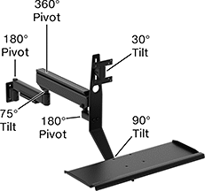
Swing-Joint Positioning Arms
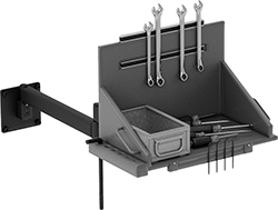 | 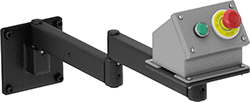 |
Shown with a Toolbox Installed | Shown with a Control Box Installed |
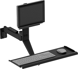 | 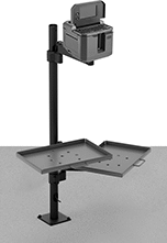 |
Shown in Use with Monitor, Keyboard, and Mouse | Shown with a Printer Installed |
 | |
Shown with a Monitor Installed |
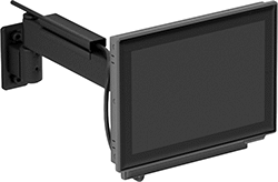
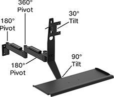
Ready-to-Use Arms with Monitor Mounting Plate
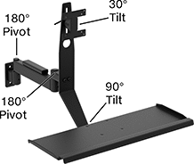 |  |
Wall Mount Style G | Wall Mount Style H |
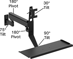 |  |
Wall Mount Style J | Wall Mount Style K |
Load Capacity, lb. | Base | Attaching End | Keyboard Tray | ||||||||||||||||||
|---|---|---|---|---|---|---|---|---|---|---|---|---|---|---|---|---|---|---|---|---|---|
Style | Max. Projection | Min. | Max. | Material | Color | Lg. | Wd. | Mounting Fasteners Included | Mounting Hole Dia. (No. of) | Lg. | Wd. | Mounting Pattern Compatibility | Mounting Hole Dia. | No. of Mounting Holes | Lg. | Wd. | Each | ||||
Wall Mount | |||||||||||||||||||||
| G | 29" | — | 25 | Powder-Coated Steel | Black | 4 1/2" | 2" | No | 13/32" | 2 | 4 1/2" | 4 1/2" | VESA 75 × 75, VESA 100 × 100 | 3/16" | 8 | 8" | 25" | 5164T34 | 0000000 | ||
| H | 41" | — | 25 | Powder-Coated Steel | Black | 4 1/2" | 2" | No | 13/32" | 2 | 4 1/2" | 4 1/2" | VESA 75 × 75, VESA 100 × 100 | 3/16" | 8 | 8" | 25" | 5164T35 | 000000 | ||
| J | 36" | 4 | 21 | Powder-Coated Steel | Black | 6" | 2 1/2" | No | 13/32" | 3 | 4 1/2" | 4 1/2" | VESA 75 × 75, VESA 100 × 100 | 3/16" | 8 | 8" | 25" | 5164T38 | 000000 | ||
| K | 43" | 18 | 43 | Powder-Coated Steel | Black | 4 1/2" | 2" | No | 13/32" | 2 | 4 1/2" | 4 1/2" | VESA 75 × 75, VESA 100 × 100 | 3/16" | 8 | 8" | 25" | 5164T37 | 000000 | ||
Keyboard Trays
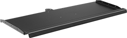 |
Keyboard trays hold a computer keyboard and mouse.
Mounting | ||||||||||||||
|---|---|---|---|---|---|---|---|---|---|---|---|---|---|---|
For Pin Dia. | Lg. | Wd. | Ht. | Lip Ht. | Max. Load Cap., lb. | Material | Color | Fasteners Included | Hole Dia. (No. of) | Each | ||||
| 7/8" | 8" | 25" | 3/4" | 3/4" | 25 | Powder-Coated Aluminum | Black | Yes | 7/8" | 1 | 5164T956 | 0000000 | ||
