


Carbide Inserts for Multiple Materials
Choose these premium carbide inserts to turn a variety of materials without changing out your tool. They’re made of higher-quality carbide than economy inserts, so they last longer and create a smoother finish. Install them into a matching holder. For the best performance, choose an insert designed for the material of your workpiece.
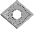
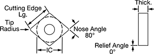
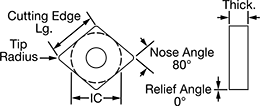
Inserts with a larger nose angle and tip radius remove more material with each pass, but they cut less precisely than smaller inserts. Select the insert with the largest nose angle and tip radius that will turn your workpiece to the shape you want.
Inserts for semi-interrupted cutting conditions are used to machine imperfectly round workpieces, such as shafts with a keyway. They’re the most common type of insert.
Negative-rake inserts are the first choice for most turning applications. With strong cutting edges on two faces, they last longer than comparable positive-rake inserts. When all the edges on one face are worn, flip the insert over. Use finishing inserts at the end of your turning process to remove minimal material for a smooth surface finish.
Inserts with a titanium aluminum nitride (TiAlN) coating dissipate heat well, especially at high speeds. The coating reacts to high temperatures by forming a layer of aluminum oxide. This layer transfers heat to the chips, so the tool stays cool even without lubrication.
Inserts with chip breakers prevent long chips from forming, so they won’t block the flow of coolant or damage your tool.
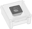
Inserts sold in packs come factory sealed from the manufacturer for maximum traceability. Inserts sold individually come packed in a clear plastic case to protect cutting edges during shipment.
Each | Package | ||||||||||||
|---|---|---|---|---|---|---|---|---|---|---|---|---|---|
| Insert Code | Inscribed Circle Dia. (IC) | Tip Radius | Thick. | Cutting Edge Lg. | Rake Type | For Cutting Operation | Finish | Features | Each | Pkg. Qty. | Pkg. | ||
For Use On Brass, Bronze, Copper, Nickel, Plastic, Steel, Titanium | |||||||||||||
For Semi-Interrupted Cutting Conditions | |||||||||||||
| CNGG-431 | 1/2" | 1/64" | 3/16" | 0.33" | Negative | Finishing | Titanium Aluminum Nitride (TiAlN) Coated | Chip Breakers | 00000000 | 000000 | 10 | 00000000 | 0000000 |
| CNGG-432 | 1/2" | 1/32" | 3/16" | 0.33" | Negative | Finishing | Titanium Aluminum Nitride (TiAlN) Coated | Chip Breakers | 00000000 | 00000 | 10 | 00000000 | 000000 |
Carbide Inserts for Heat-Resistant Super Alloys
Heat resistant and wear resistant, these inserts cut super alloys—such as Inconel and Waspaloy—and titanium better than premium general use inserts. Install inserts into a matching holder.
Inserts with a larger nose angle and tip radius remove more material with each pass but cut less precisely than smaller inserts. Select the insert with the largest nose angle and tip radius that will turn your workpiece to the desired shape.
Negative-rake inserts are the first choice for most turning applications. With strong cutting edges on two faces, they last longer than comparable positive-rake inserts. When all the edges on one face are worn, flip the insert over.
Use finishing inserts at the end of your turning process to remove minimal material for a smooth surface finish.
Choose inserts for continuous cutting conditions when machining pieces that allow for constant contact between the insert and the workpiece, such as round rods. Inserts for semi-interrupted cutting conditions are the most commonly used, often to machine imperfectly round workpieces, such as shafts with a keyway. Inserts for interrupted cutting conditions are best for workpieces that will come in and out of contact with the insert, such as hexagonal bars.
Inserts sold individually come packed in a clear plastic case to protect cutting edges during shipment. Inserts sold in packs come factory sealed from the manufacturer for maximum traceability.
| Insert Code | Inscribed Circle Dia. (IC) | Tip Radius | Thick. | Cutting Edge Lg. | Rake Type | For Cutting Operation | Finish | Each | |
For Continuous Cutting Conditions | |||||||||
|---|---|---|---|---|---|---|---|---|---|
| CNGG-431 | 1/2" | 1/64" | 3/16" | 0.33" | Negative | Finishing | Titanium Aluminum Nitride (TiAlN) Coated | 00000000 | 000000 |
| CNGG-432 | 1/2" | 1/32" | 3/16" | 0.33" | Negative | Finishing | Titanium Aluminum Nitride (TiAlN) Coated | 00000000 | 00000 |
For Semi-Interrupted Cutting Conditions | |||||||||
| CNGG-431 | 1/2" | 1/64" | 3/16" | 0.33" | Negative | Finishing | Uncoated | 00000000 | 00000 |
| CNGG-432 | 1/2" | 1/32" | 3/16" | 0.33" | Negative | Finishing | Uncoated | 00000000 | 00000 |
For Interrupted Cutting Conditions | |||||||||
| CNGG-431 | 1/2" | 1/64" | 3/16" | 0.33" | Negative | Finishing | Titanium Aluminum Nitride (TiAlN) Coated | 00000000 | 00000 |
| CNGG-432 | 1/2" | 1/32" | 3/16" | 0.33" | Negative | Finishing | Titanium Aluminum Nitride (TiAlN) Coated | 00000000 | 00000 |
| Insert Code | Inscribed Circle Dia. (IC) | Tip Radius | Thick. | Cutting Edge Lg. | Rake Type | For Cutting Operation | Finish | Pkg. Qty. | Pkg. | |
For Continuous Cutting Conditions | ||||||||||
|---|---|---|---|---|---|---|---|---|---|---|
| CNGG-431 | 1/2" | 1/64" | 3/16" | 0.33" | Negative | Finishing | Titanium Aluminum Nitride (TiAlN) Coated | 10 | 0000000 | 0000000 |
| CNGG-432 | 1/2" | 1/32" | 3/16" | 0.33" | Negative | Finishing | Titanium Aluminum Nitride (TiAlN) Coated | 10 | 0000000 | 000000 |
For Semi-Interrupted Cutting Conditions | ||||||||||
| CNGG-431 | 1/2" | 1/64" | 3/16" | 0.33" | Negative | Finishing | Uncoated | 10 | 00000000 | 000000 |
| CNGG-432 | 1/2" | 1/32" | 3/16" | 0.33" | Negative | Finishing | Uncoated | 10 | 0000000 | 000000 |
For Interrupted Cutting Conditions | ||||||||||
| CNGG-431 | 1/2" | 1/64" | 3/16" | 0.33" | Negative | Finishing | Titanium Aluminum Nitride (TiAlN) Coated | 10 | 000000 | 000000 |
| CNGG-432 | 1/2" | 1/32" | 3/16" | 0.33" | Negative | Finishing | Titanium Aluminum Nitride (TiAlN) Coated | 10 | 0000000 | 000000 |
Turning Carbide Insert Holders
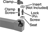
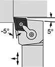
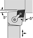
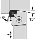
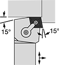
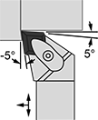
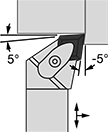
Secure carbide inserts inside these holders for stable turning. They’re also known as indexable insert holders. Select a holder that’s compatible with your insert by matching the insert style and inscribed circle diameter (IC). Right-hand holders move from right to left toward the lathe chuck, left-hand holders move from left to right away from the lathe chuck, and neutral holders can cut in either direction.
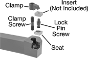
M-code holders secure inserts with both a top clamp and a pin lock, so they’re often used for interrupted or semi-interrupted cuts to keep inserts stable despite vibration. They’re the most commonly used holders with negative-rake inserts.
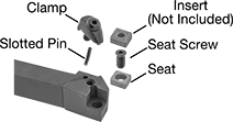
D-code holders require just a quick motion to remove inserts from their wedge clamp. However, they hold inserts less securely than M-code holders.
Holders with an offset shank are good for reaching into tight corners and when working close to the chuck.
Holders | ||||||||||||||
|---|---|---|---|---|---|---|---|---|---|---|---|---|---|---|
For Insert | Shank | Replacement Clamps | Replacement Clamp Screws | Replacement Lock Pin Screws | Replacement Seats | |||||||||
| Inscribed Circle Dia. (IC) | Thick. | Wd. | Ht. | O'all Lg. | Each | Each | Each | Each | Each | |||||
For Along-the-Length Turning, Chamfering, Facing | ||||||||||||||
Right Hand | ||||||||||||||
| 1/2" | 3/16" | 3/4" | 3/4" | 4 1/2" | 00000000 | 000000 | 00000000 | 00000 | 00000000 | 00000 | 00000000 | 00000 | 00000000 | 00000 |
| 1/2" | 3/16" | 1" | 1" | 6" | 00000000 | 00000 | 00000000 | 0000 | 00000000 | 0000 | 00000000 | 0000 | 00000000 | 0000 |
| 5/8" | 1/4" | 1" | 1" | 6" | 00000000 | 000000 | 00000000 | 0000 | 00000000 | 0000 | 00000000 | 0000 | 00000000 | 0000 |
| 3/4" | 1/4" | 1" | 1" | 6" | 00000000 | 000000 | 00000000 | 0000 | 00000000 | 0000 | 00000000 | 0000 | 00000000 | 00000 |
Left Hand | ||||||||||||||
| 1/2" | 3/16" | 3/4" | 3/4" | 4 1/2" | 00000000 | 00000 | 00000000 | 0000 | 00000000 | 0000 | 00000000 | 0000 | 00000000 | 0000 |
| 1/2" | 3/16" | 1" | 1" | 6" | 00000000 | 00000 | 00000000 | 0000 | 00000000 | 0000 | 00000000 | 0000 | 00000000 | 0000 |
| 5/8" | 1/4" | 1" | 1" | 6" | 00000000 | 000000 | 00000000 | 0000 | 00000000 | 0000 | 00000000 | 0000 | 00000000 | 0000 |
| 3/4" | 1/4" | 1" | 1" | 6" | 00000000 | 000000 | 00000000 | 0000 | 00000000 | 0000 | 00000000 | 0000 | 00000000 | 00000 |
Holders | ||||||||||||||
|---|---|---|---|---|---|---|---|---|---|---|---|---|---|---|
For Insert | Shank | Replacement Clamps | Replacement Clamp Screws | Replacement Lock Pin Screws | Replacement Seats | |||||||||
| Inscribed Circle Dia. (IC) | Thick. | Wd. | Ht. | O'all Lg. | Each | Each | Each | Each | Each | |||||
For Along-the-Length Turning, Chamfering, Facing | ||||||||||||||
Right Hand | ||||||||||||||
| 1/2" | 3/16" | 1" | 1" | 6" | 00000000 | 000000 | 00000000 | 00000 | 00000000 | 00000 | 00000000 | 00000 | 00000000 | 00000 |
| 5/8" | 1/4" | 1" | 1" | 6" | 00000000 | 000000 | 00000000 | 0000 | 00000000 | 0000 | 00000000 | 0000 | 00000000 | 0000 |
Left Hand | ||||||||||||||
| 1/2" | 3/16" | 1" | 1" | 6" | 00000000 | 00000 | 00000000 | 0000 | 00000000 | 0000 | 00000000 | 0000 | 00000000 | 0000 |
| 5/8" | 1/4" | 1" | 1" | 6" | 00000000 | 000000 | 00000000 | 0000 | 00000000 | 0000 | 00000000 | 0000 | 00000000 | 0000 |
| 3/4" | 1/4" | 1" | 1" | 6" | 00000000 | 000000 | 00000000 | 0000 | 00000000 | 0000 | 00000000 | 0000 | 00000000 | 00000 |
Holders | ||||||||||||||
|---|---|---|---|---|---|---|---|---|---|---|---|---|---|---|
For Insert | Shank | Replacement Clamps | Replacement Seats | Replacement Seat Screws | Replacement Slotted Pins | |||||||||
| Inscribed Circle Dia. (IC) | Thick. | Wd. | Ht. | O'all Lg. | Each | Each | Each | Each | Each | |||||
For Along-the-Length Turning, Facing | ||||||||||||||
Right Hand | ||||||||||||||
| 1/2" | 3/16" | 3/4" | 3/4" | 4 1/2" | 00000000 | 000000 | 00000000 | 000000 | 00000000 | 000000 | 00000000 | 000000 | 00000000 | 00000 |
| 1/2" | 3/16" | 1" | 1" | 6" | 00000000 | 00000 | 00000000 | 00000 | 00000000 | 00000 | 00000000 | 00000 | 00000000 | 000 |
| 5/8" | 1/4" | 1" | 1" | 6" | 00000000 | 00000 | 00000000 | 00000 | 00000000 | 00000 | 00000000 | 00000 | 00000000 | 000 |
Left Hand | ||||||||||||||
| 1/2" | 3/16" | 3/4" | 3/4" | 4 1/2" | 00000000 | 00000 | 00000000 | 00000 | 00000000 | 00000 | 00000000 | 00000 | 00000000 | 000 |
| 1/2" | 3/16" | 1" | 1" | 6" | 00000000 | 00000 | 00000000 | 00000 | 00000000 | 00000 | 00000000 | 00000 | 00000000 | 000 |
| 5/8" | 1/4" | 1" | 1" | 6" | 00000000 | 00000 | 00000000 | 00000 | 00000000 | 00000 | 00000000 | 00000 | 00000000 | 000 |
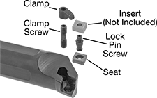
Boring Carbide Insert Holders
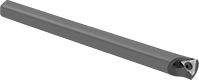
These holders conform to ANSI standards. Pair them with an ANSI standard carbide insert (sold separately) to enlarge existing holes to precise diameters. When one edge of the insert dulls, just rotate it to use another edge. Right-hand holders are for boring when the workpiece is rotating counterclockwise (toward the lathe operator). Left-hand holders are for boring when the workpiece is rotating clockwise (away from the lathe operator).

Holders | |||||||||||||||
|---|---|---|---|---|---|---|---|---|---|---|---|---|---|---|---|
For Insert | Replacement Clamps | Replacement Clamp Screws | Replacement Seats | Replacement Lock Pin Screws | |||||||||||
| Inscribed Circle Dia. (IC) | Thick. | Shank Dia. | Min. Hole Dia. | Max. Hole Dp. | O'all Lg. | Each | Each | Each | Each | Each | |||||
Right Hand | |||||||||||||||
| 1/2" | 3/16" | 3/4" | 1" | 3" | 10" | 0000000 | 0000000 | 0000000 | 00000 | 00000000 | 00000 | 000000 | 00 | 0000000 | 00000 |
| 1/2" | 3/16" | 1" | 1 5/16" | 4" | 12" | 0000000 | 000000 | 00000000 | 0000 | 00000000 | 0000 | 000000 | 00 | 0000000 | 0000 |
| 1/2" | 3/16" | 1 1/4" | 1 9/16" | 5" | 14" | 0000000 | 000000 | 00000000 | 0000 | 00000000 | 0000 | 00000000 | 00000 | 00000000 | 0000 |
| 1/2" | 3/16" | 1 1/2" | 1 13/16" | 6" | 14" | 0000000 | 000000 | 00000000 | 0000 | 00000000 | 0000 | 00000000 | 0000 | 00000000 | 0000 |
Left Hand | |||||||||||||||
| 1/2" | 3/16" | 3/4" | 1" | 3" | 10" | 0000000 | 000000 | 0000000 | 0000 | 00000000 | 0000 | 000000 | 00 | 0000000 | 0000 |
| 1/2" | 3/16" | 1" | 1 5/16" | 4" | 12" | 0000000 | 000000 | 00000000 | 0000 | 00000000 | 0000 | 000000 | 00 | 0000000 | 0000 |
| 1/2" | 3/16" | 1 1/4" | 1 9/16" | 5" | 14" | 0000000 | 000000 | 00000000 | 0000 | 00000000 | 0000 | 00000000 | 0000 | 00000000 | 0000 |
| 1/2" | 3/16" | 1 1/2" | 1 13/16" | 6" | 14" | 0000000 | 000000 | 00000000 | 0000 | 00000000 | 0000 | 00000000 | 0000 | 00000000 | 0000 |