


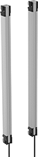
Safety Light Curtains
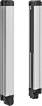 |
Transmitter and Receiver |
5-Pole M12 Plug |
4-Pole M12 Plug |
8-Pole M12 Plug |
 |
Light Curtains | Replacement Fixed Brackets | Swivel Brackets | |||||||||||||||||||||
|---|---|---|---|---|---|---|---|---|---|---|---|---|---|---|---|---|---|---|---|---|---|---|---|
Plug Type | |||||||||||||||||||||||
Light Beam Ht. | Light Beam Switch Operation | Sensing Distance, ft. | Input Voltage, V DC | Current Output, mA | Max. Load Current, mA | Output Digital Signal | Transmitter | Receiver | Ht. | Wd. | Dp. | Housing Material | Color | Each | Pkg. Qty. | Pkg. | Pkg. Qty. | Pkg. | |||||
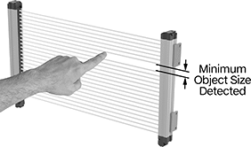
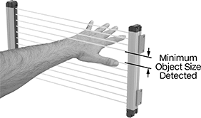
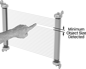
0.55" Minimum Object Size Detected | |||||||||||||||||||||||
Four Fixed Mounting Brackets | |||||||||||||||||||||||
| 6.3" | On When Object Absent | 1 to 32 | 24 | 115 | 300 | PNP/NPN | 5-Pole M12 | 8-Pole M12 | 8.2" | 1.4" | 1.4" | Painted Aluminum | Yellow | 7774K39 | 000000000 | 2 | 7774K64 | 000000 | 2 | 7774K62 | 0000000 | ||
| 9.4" | On When Object Absent | 1 to 32 | 24 | 120 | 300 | PNP/NPN | 5-Pole M12 | 8-Pole M12 | 11.3" | 1.4" | 1.4" | Painted Aluminum | Yellow | 7774K41 | 00000000 | 2 | 7774K64 | 00000 | 2 | 7774K62 | 000000 | ||
| 12.6" | On When Object Absent | 1 to 32 | 24 | 130 | 300 | PNP/NPN | 5-Pole M12 | 8-Pole M12 | 14.5" | 1.4" | 1.4" | Painted Aluminum | Yellow | 7774K43 | 00000000 | 2 | 7774K64 | 00000 | 2 | 7774K62 | 000000 | ||
| 15.7" | On When Object Absent | 1 to 32 | 24 | 140 | 300 | PNP/NPN | 5-Pole M12 | 8-Pole M12 | 17.6" | 1.4" | 1.4" | Painted Aluminum | Yellow | 7774K44 | 00000000 | 2 | 7774K64 | 00000 | 2 | 7774K62 | 000000 | ||
| 18.9" | On When Object Absent | 1 to 32 | 24 | 130 | 300 | PNP/NPN | 5-Pole M12 | 8-Pole M12 | 20.8" | 1.4" | 1.4" | Painted Aluminum | Yellow | 7774K42 | 00000000 | 2 | 7774K64 | 00000 | 2 | 7774K62 | 000000 | ||
| 22" | On When Object Absent | 1 to 32 | 24 | 135 | 300 | PNP/NPN | 5-Pole M12 | 8-Pole M12 | 23.9" | 1.4" | 1.4" | Painted Aluminum | Yellow | 7774K45 | 00000000 | 2 | 7774K64 | 00000 | 2 | 7774K62 | 000000 | ||
| 28.3" | On When Object Absent | 1 to 32 | 24 | 150 | 300 | PNP/NPN | 5-Pole M12 | 8-Pole M12 | 30.2" | 1.4" | 1.4" | Painted Aluminum | Yellow | 7774K46 | 00000000 | 2 | 7774K64 | 00000 | 2 | 7774K62 | 000000 | ||
| 34.6" | On When Object Absent | 1 to 32 | 24 | 160 | 300 | PNP/NPN | 5-Pole M12 | 8-Pole M12 | 36.5" | 1.4" | 1.4" | Painted Aluminum | Yellow | 7774K47 | 00000000 | 2 | 7774K64 | 00000 | 2 | 7774K62 | 000000 | ||
| 47.2" | On When Object Absent | 1 to 32 | 24 | 190 | 300 | PNP/NPN | 5-Pole M12 | 8-Pole M12 | 49.1" | 1.4" | 1.4" | Painted Aluminum | Yellow | 7774K48 | 00000000 | 2 | 7774K64 | 00000 | 2 | 7774K62 | 000000 | ||
0.55" Minimum Object Size Detected—Bluetooth | |||||||||||||||||||||||
Four Fixed Mounting Brackets | |||||||||||||||||||||||
| 9.8" | On When Object Absent | 10 to 32 | 24 | 900 | — | PNP | 4-Pole M12 | 8-Pole M12 | 14.3" | 1.1" | 1.3" | Painted Aluminum | Yellow | 7774K122 | 00000000 | — | ——— | 0 | — | ——— | 0 | ||
| 13" | On When Object Absent | 10 to 32 | 24 | 900 | — | PNP | 4-Pole M12 | 8-Pole M12 | 17.4" | 1.1" | 1.3" | Painted Aluminum | Yellow | 7774K123 | 00000000 | — | ——— | 0 | — | ——— | 0 | ||
| 22.4" | On When Object Absent | 10 to 32 | 24 | 900 | — | PNP | 4-Pole M12 | 8-Pole M12 | 26.9" | 1.1" | 1.3" | Painted Aluminum | Yellow | 7774K124 | 00000000 | — | ——— | 0 | — | ——— | 0 | ||
| 28.7" | On When Object Absent | 10 to 32 | 24 | 900 | — | PNP | 4-Pole M12 | 8-Pole M12 | 33.2" | 1.1" | 1.3" | Painted Aluminum | Yellow | 7774K125 | 00000000 | — | ——— | 0 | — | ——— | 0 | ||
 |
AC Switching Current @ Voltage | DC Switching Current @ Voltage | ||||||||||||||||
|---|---|---|---|---|---|---|---|---|---|---|---|---|---|---|---|---|---|
No. of Terminals | Input Voltage, V DC | Current, amp | Voltage, V AC | Current, amp | Voltage, V DC | Max. Switching Voltage, V AC | Wire Connection | Ht. | Wd. | Dp. | For Use With | Max. System Safety Rating | Features | Each | |||
2 Circuits Controlled | |||||||||||||||||
2 Off Switch Starting Position | |||||||||||||||||
| 14 | 24 | 2 | 240 | 1.5 | 24 | 250 | Terminal Block | 4.9" | 0.69" | 4.3" | Emergency Stops, Safety Light Curtains | PLe, SIL 3, Cat. 4 | Auxiliary PNP Output, LED Indicator | 7774K73 | 0000000 | ||
4 Circuits Controlled | |||||||||||||||||
4 Off Switch Starting Position | |||||||||||||||||
| 18 | 24 | 2 | 240 | 1.5 | 24 | 250 | Terminal Block | 4.9" | 0.89" | 4.3" | Emergency Stops, Safety Light Curtains | PLe, SIL 3, Cat. 4 | Auxiliary PNP Output, LED Indicator | 7774K76 | 000000 | ||
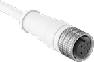 | |
4-Pole M12 Socket |
No. of Poles | Gender | Electrical Connection | Lg., ft. | Each | ||
|---|---|---|---|---|---|---|
| 4 | Female | Wire Leads | 12 | 6897K36 | 000000 |
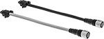 | |||
Transmitter Connectors | Receiver Connectors | Receiver Extension Cords | Transmitter and Receiver Connecting Cords |
8-Pole M12 Plug | 5-Pole Micro M12 Socket | 8-Pole M12 Socket |
Component | No. of Poles | Gender | Wire Connection | No. of Cords | Cable Lead Lg. | Each | ||
|---|---|---|---|---|---|---|---|---|
| Transmitter Connector | 5 | Female | Wire Leads | — | 32 1/2 ft. | 7774K52 | 000000 | |
| Receiver Connector | 8 | Female | Wire Leads | — | 32 1/2 ft. | 7774K51 | 000000 | |
| Receiver Extension Cord | 8 | Female × Male | — | — | 9 1/2 ft. | 7774K55 | 00000 | |
| Transmitter and Receiver Connecting Cords | 5, 8 | Female | — | 2 | 8" | 7774K57 | 000000 |
 |
Light Curtains | Replacement Fixed Brackets | Swivel Brackets | ||||||||||||||||||||
|---|---|---|---|---|---|---|---|---|---|---|---|---|---|---|---|---|---|---|---|---|---|---|
Plug Type | ||||||||||||||||||||||
Light Beam Ht. | Light Beam Switch Operation | Sensing Distance, ft. | Input Voltage, V DC | Current Output, mA | Output Digital Signal | Transmitter | Receiver | Ht. | Wd. | Dp. | Housing Material | Color | Each | Pkg. Qty. | Pkg. | Pkg. Qty. | Pkg. | |||||
0.98" Minimum Object Size Detected | ||||||||||||||||||||||
| 6.3" | On When Object Absent | 1 to 65 | 24 | 155 | PNP/NPN | 5-Pole M12 | 8-Pole M12 | 6.3" | 1.3" | 1.5" | Painted Aluminum | Yellow | 7774K111 | 0000000 | 2 | 8690N15 | 000000 | 2 | 7774K121 | 0000000 | ||
| 9.4" | On When Object Absent | 1 to 65 | 24 | 160 | PNP/NPN | 5-Pole M12 | 8-Pole M12 | 9.4" | 1.3" | 1.5" | Painted Aluminum | Yellow | 7774K112 | 000000 | 2 | 8690N15 | 00000 | 2 | 7774K121 | 000000 | ||
| 12.6" | On When Object Absent | 1 to 65 | 24 | 160 | PNP/NPN | 5-Pole M12 | 8-Pole M12 | 12.6" | 1.3" | 1.5" | Painted Aluminum | Yellow | 7774K113 | 000000 | 2 | 8690N15 | 00000 | 2 | 7774K121 | 000000 | ||
| 15.7" | On When Object Absent | 1 to 65 | 24 | 160 | PNP/NPN | 5-Pole M12 | 8-Pole M12 | 15.7" | 1.3" | 1.5" | Painted Aluminum | Yellow | 7774K114 | 000000 | 2 | 8690N15 | 00000 | 2 | 7774K121 | 000000 | ||
| 18.9" | On When Object Absent | 1 to 65 | 24 | 165 | PNP/NPN | 5-Pole M12 | 8-Pole M12 | 18.9" | 1.3" | 1.5" | Painted Aluminum | Yellow | 7774K115 | 00000000 | 2 | 8690N15 | 00000 | 2 | 7774K121 | 000000 | ||
| 22" | On When Object Absent | 1 to 65 | 24 | 165 | PNP/NPN | 5-Pole M12 | 8-Pole M12 | 22" | 1.3" | 1.5" | Painted Aluminum | Yellow | 7774K116 | 00000000 | 2 | 8690N15 | 00000 | 2 | 7774K121 | 000000 | ||
| 28.3" | On When Object Absent | 1 to 65 | 24 | 175 | PNP/NPN | 5-Pole M12 | 8-Pole M12 | 28.3" | 1.3" | 1.5" | Painted Aluminum | Yellow | 7774K117 | 00000000 | 2 | 8690N15 | 00000 | 2 | 7774K121 | 000000 | ||
| 34.6" | On When Object Absent | 1 to 65 | 24 | 180 | PNP/NPN | 5-Pole M12 | 8-Pole M12 | 34.6" | 1.3" | 1.5" | Painted Aluminum | Yellow | 7774K118 | 00000000 | 2 | 8690N15 | 00000 | 2 | 7774K121 | 000000 | ||
| 47.2" | On When Object Absent | 1 to 65 | 24 | 190 | PNP/NPN | 5-Pole M12 | 8-Pole M12 | 47.2" | 1.3" | 1.5" | Painted Aluminum | Yellow | 7774K119 | 00000000 | 2 | 8690N15 | 00000 | 2 | 7774K121 | 000000 | ||
|
AC Switching Current @ Voltage | DC Switching Current @ Voltage | ||||||||||||||||
|---|---|---|---|---|---|---|---|---|---|---|---|---|---|---|---|---|---|
No. of Terminals | Input Voltage, V DC | Current, amp | Voltage, V AC | Current, amp | Voltage, V DC | Max. Switching Voltage, V AC | Wire Connection | Ht. | Wd. | Dp. | For Use With | Max. System Safety Rating | Features | Each | |||
2 Circuits Controlled | |||||||||||||||||
2 Off Switch Starting Position | |||||||||||||||||
| 14 | 24 | 2 | 240 | 1.5 | 24 | 250 | Terminal Block | 4.9" | 0.69" | 4.3" | Emergency Stops, Safety Light Curtains | PLe, SIL 3, Cat. 4 | Auxiliary PNP Output, LED Indicator | 7774K73 | 0000000 | ||
4 Circuits Controlled | |||||||||||||||||
4 Off Switch Starting Position | |||||||||||||||||
| 18 | 24 | 2 | 240 | 1.5 | 24 | 250 | Terminal Block | 4.9" | 0.89" | 4.3" | Emergency Stops, Safety Light Curtains | PLe, SIL 3, Cat. 4 | Auxiliary PNP Output, LED Indicator | 7774K76 | 000000 | ||
| |||
Transmitter Connectors | Receiver Connectors | Receiver Extension Cords | Transmitter and Receiver Connecting Cords |
8-Pole M12 Plug | 5-Pole Micro M12 Socket | 8-Pole M12 Socket |
Component | No. of Poles | Gender | Wire Connection | No. of Cords | Cable Lead Lg. | Each | ||
|---|---|---|---|---|---|---|---|---|
| Transmitter Connector | 5 | Female | Wire Leads | — | 32 1/2 ft. | 7774K52 | 000000 | |
| Receiver Connector | 8 | Female | Wire Leads | — | 32 1/2 ft. | 7774K51 | 000000 | |
| Receiver Extension Cord | 8 | Female × Male | — | — | 9 1/2 ft. | 7774K55 | 00000 | |
| Transmitter and Receiver Connecting Cords | 5, 8 | Female | — | 2 | 8" | 7774K57 | 000000 |
Safety Relays with Diagnostic Capabilities
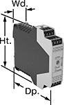 |
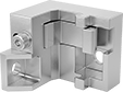
Relay with Time Delay |
No. of Terminals | Input Voltage | Switching Current @ Voltage | Max. Switching Voltage | Ht. | Wd. | Dp. | For Use With | Mounting Location | Max. System Safety Rating | Features | Each | |||
|---|---|---|---|---|---|---|---|---|---|---|---|---|---|---|
2 Circuits Controlled | ||||||||||||||
2 Off | ||||||||||||||
| 14 | 24V DC | 2 amp @ 240V AC 1.5 amp @ 24V DC | 250V AC | 4.9" | 0.69" | 4.3" | Emergency Stops, Safety Light Curtains | DIN Rail, Surface | PLe, SIL 3, Cat. 4 | Auxiliary PNP Output, LED Indicator | 7774K73 | 0000000 | ||
2 Safety Outputs with 2 Off and 2 Delayed Safety Outputs with 2 Off | ||||||||||||||
| 16 | 24V DC | 3 amp @ 240V AC 3 amp @ 24V DC | 250V AC, 250V DC | 3.9" | 0.9" | 4.5" | Emergency Stops, Safety Light Curtains | DIN Rail | PLe, SIL 3 | Time Delay | 6322N15 | 000000 | ||
4 Circuits Controlled | ||||||||||||||
4 Off | ||||||||||||||
| 18 | 24V DC | 2 amp @ 240V AC 1.5 amp @ 24V DC | 250V AC | 4.9" | 0.89" | 4.3" | Emergency Stops, Safety Light Curtains | DIN Rail, Surface | PLe, SIL 3, Cat. 4 | Auxiliary PNP Output, LED Indicator | 7774K76 | 000000 | ||
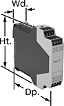 |  |
Auxiliary Contact Block | Auxiliary Contact Block with Time Delay |
No. of Terminals | Input Voltage, V DC | Switching Current @ Voltage | Max. Switching Voltage | Ht. | Wd. | Dp. | Features | Each | |||
|---|---|---|---|---|---|---|---|---|---|---|---|
5 Safety Outputs | |||||||||||
| 16 | 24 | 3 amp @ 240V AC 2.5 amp @ 24V DC | 250V AC, 250V DC | 3.9" | 0.9" | 4.5" | — | 6322N22 | 0000000 | ||
4 Delayed Safety Outputs | |||||||||||
| 16 | 24 | 3 amp @ 240V AC 3 amp @ 24V DC | 250V AC, 250V DC | 3.9" | 0.9" | 4.5" | Time Delay | 6322N18 | 000000 | ||
Harsh Environment Safety Light Curtains
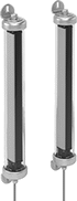 |
Transmitter and Receiver |
4-Pole M12 Plug |
5-Pole M12 Plug |
 |
Plug Type | ||||||||||||||||||
|---|---|---|---|---|---|---|---|---|---|---|---|---|---|---|---|---|---|---|
Light Beam Ht. | Light Beam Switch Operation | Sensing Distance, ft. | Input Voltage, V DC | Current Output, mA | Output Digital Signal | Transmitter | Receiver | Ht. | Wd. | Dp. | Housing Material | Color | Includes | Cable Lg., ft. | Each | |||
0.55" Minimum Object Size Detected—Bluetooth | ||||||||||||||||||
| 13" | On When Object Absent | 1 to 23 | 24 | 700 | PNP | 4-Pole M12 | 5-Pole M12 | 18.1" | 2.4" | 2.4" | Polycarbonate | Yellow | Four Fixed Mounting Brackets | 33 | 8403N11 | 000000000 | ||
| 19.3" | On When Object Absent | 1 to 23 | 24 | 700 | PNP | 4-Pole M12 | 5-Pole M12 | 24.4" | 2.4" | 2.4" | Polycarbonate | Yellow | Four Fixed Mounting Brackets | 33 | 8403N13 | 00000000 | ||
| 25.6" | On When Object Absent | 1 to 23 | 24 | 700 | PNP | 4-Pole M12 | 5-Pole M12 | 30.7" | 2.4" | 2.4" | Polycarbonate | Yellow | Four Fixed Mounting Brackets | 33 | 8403N15 | 00000000 | ||
| 28.7" | On When Object Absent | 1 to 23 | 24 | 700 | PNP | 4-Pole M12 | 5-Pole M12 | 33.9" | 2.4" | 2.4" | Polycarbonate | Yellow | Four Fixed Mounting Brackets | 33 | 8403N17 | 00000000 | ||
| 35" | On When Object Absent | 1 to 23 | 24 | 700 | PNP | 4-Pole M12 | 5-Pole M12 | 40.2" | 2.4" | 2.4" | Polycarbonate | Yellow | Four Fixed Mounting Brackets | 33 | 8403N19 | 00000000 | ||
| 38.2" | On When Object Absent | 1 to 23 | 24 | 700 | PNP | 4-Pole M12 | 5-Pole M12 | 43.3" | 2.4" | 2.4" | Polycarbonate | Yellow | Four Fixed Mounting Brackets | 33 | 8403N22 | 00000000 | ||
| 47.6" | On When Object Absent | 1 to 23 | 24 | 700 | PNP | 4-Pole M12 | 5-Pole M12 | 52.8" | 2.4" | 2.4" | Polycarbonate | Yellow | Four Fixed Mounting Brackets | 33 | 8403N24 | 00000000 | ||
| 53.9" | On When Object Absent | 1 to 23 | 24 | 700 | PNP | 4-Pole M12 | 5-Pole M12 | 59.1" | 2.4" | 2.4" | Polycarbonate | Yellow | Four Fixed Mounting Brackets | 33 | 8403N26 | 00000000 | ||
|
AC Switching Current @ Voltage | DC Switching Current @ Voltage | ||||||||||||||||
|---|---|---|---|---|---|---|---|---|---|---|---|---|---|---|---|---|---|
No. of Terminals | Input Voltage, V DC | Current, amp | Voltage, V AC | Current, amp | Voltage, V DC | Max. Switching Voltage, V AC | Wire Connection | Ht. | Wd. | Dp. | For Use With | Max. System Safety Rating | Features | Each | |||
2 Circuits Controlled | |||||||||||||||||
2 Off Switch Starting Position | |||||||||||||||||
| 14 | 24 | 2 | 240 | 1.5 | 24 | 250 | Terminal Block | 4.9" | 0.69" | 4.3" | Emergency Stops, Safety Light Curtains | PLe, SIL 3, Cat. 4 | Auxiliary PNP Output, LED Indicator | 7774K73 | 0000000 | ||
4 Circuits Controlled | |||||||||||||||||
4 Off Switch Starting Position | |||||||||||||||||
| 18 | 24 | 2 | 240 | 1.5 | 24 | 250 | Terminal Block | 4.9" | 0.89" | 4.3" | Emergency Stops, Safety Light Curtains | PLe, SIL 3, Cat. 4 | Auxiliary PNP Output, LED Indicator | 7774K76 | 000000 | ||
 |
Plug Type | ||||||||||||||||||
|---|---|---|---|---|---|---|---|---|---|---|---|---|---|---|---|---|---|---|
Light Beam Ht. | Light Beam Switch Operation | Sensing Distance, ft. | Input Voltage, V DC | Current Output, mA | Output Digital Signal | Transmitter | Receiver | Ht. | Wd. | Dp. | Housing Material | Color | Includes | Cable Lg., ft. | Each | |||
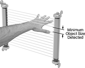
1.18" Minimum Object Size Detected | ||||||||||||||||||
| 13" | On When Object Absent | 1 to 32 | 24 | 700 | PNP | 4-Pole M12 | 5-Pole M12 | 18.1" | 2.4" | 2.4" | Polycarbonate | Yellow | Four Fixed Mounting Brackets | 33 | 8403N12 | 000000000 | ||
| 19.3" | On When Object Absent | 1 to 32 | 24 | 700 | PNP | 4-Pole M12 | 5-Pole M12 | 24.4" | 2.4" | 2.4" | Polycarbonate | Yellow | Four Fixed Mounting Brackets | 33 | 8403N14 | 00000000 | ||
| 25.6" | On When Object Absent | 1 to 32 | 24 | 700 | PNP | 4-Pole M12 | 5-Pole M12 | 30.7" | 2.4" | 2.4" | Polycarbonate | Yellow | Four Fixed Mounting Brackets | 33 | 8403N16 | 00000000 | ||
| 28.7" | On When Object Absent | 1 to 32 | 24 | 700 | PNP | 4-Pole M12 | 5-Pole M12 | 33.9" | 2.4" | 2.4" | Polycarbonate | Yellow | Four Fixed Mounting Brackets | 33 | 8403N18 | 00000000 | ||
| 35" | On When Object Absent | 1 to 32 | 24 | 700 | PNP | 4-Pole M12 | 5-Pole M12 | 40.2" | 2.4" | 2.4" | Polycarbonate | Yellow | Four Fixed Mounting Brackets | 33 | 8403N21 | 00000000 | ||
| 38.2" | On When Object Absent | 1 to 32 | 24 | 700 | PNP | 4-Pole M12 | 5-Pole M12 | 43.3" | 2.4" | 2.4" | Polycarbonate | Yellow | Four Fixed Mounting Brackets | 33 | 8403N23 | 00000000 | ||
| 47.6" | On When Object Absent | 1 to 32 | 24 | 700 | PNP | 4-Pole M12 | 5-Pole M12 | 52.8" | 2.4" | 2.4" | Polycarbonate | Yellow | Four Fixed Mounting Brackets | 33 | 8403N25 | 00000000 | ||
| 53.9" | On When Object Absent | 1 to 32 | 24 | 700 | PNP | 4-Pole M12 | 5-Pole M12 | 59.1" | 2.4" | 2.4" | Polycarbonate | Yellow | Four Fixed Mounting Brackets | 33 | 8403N27 | 00000000 | ||
|
AC Switching Current @ Voltage | DC Switching Current @ Voltage | ||||||||||||||||
|---|---|---|---|---|---|---|---|---|---|---|---|---|---|---|---|---|---|
No. of Terminals | Input Voltage, V DC | Current, amp | Voltage, V AC | Current, amp | Voltage, V DC | Max. Switching Voltage, V AC | Wire Connection | Ht. | Wd. | Dp. | For Use With | Max. System Safety Rating | Features | Each | |||
2 Circuits Controlled | |||||||||||||||||
2 Off Switch Starting Position | |||||||||||||||||
| 14 | 24 | 2 | 240 | 1.5 | 24 | 250 | Terminal Block | 4.9" | 0.69" | 4.3" | Emergency Stops, Safety Light Curtains | PLe, SIL 3, Cat. 4 | Auxiliary PNP Output, LED Indicator | 7774K73 | 0000000 | ||
4 Circuits Controlled | |||||||||||||||||
4 Off Switch Starting Position | |||||||||||||||||
| 18 | 24 | 2 | 240 | 1.5 | 24 | 250 | Terminal Block | 4.9" | 0.89" | 4.3" | Emergency Stops, Safety Light Curtains | PLe, SIL 3, Cat. 4 | Auxiliary PNP Output, LED Indicator | 7774K76 | 000000 | ||
Safety Light Curtains for Long Distances
 |
 |  |  |
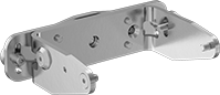
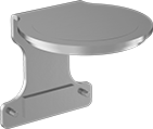
Fixed Brackets | Swivel Brackets |
Light Curtains | Replacement Fixed Brackets | Swivel Brackets | |||||||||||||||||||||
|---|---|---|---|---|---|---|---|---|---|---|---|---|---|---|---|---|---|---|---|---|---|---|---|
Plug Type | |||||||||||||||||||||||
Light Beam Ht. | Light Beam Switch Operation | Sensing Distance, ft. | Input Voltage, V DC | Current Output, mA | Output Digital Signal | Transmitter | Receiver | Ht. | Wd. | Dp. | Housing Material | Color | Cable Lg., ft. | Each | Pkg. Qty. | Pkg. | Pkg. Qty. | Pkg. | |||||
11.8" Minimum Object Size Detected | |||||||||||||||||||||||
| 35.4" | On When Object Absent | 1 to 230 | 24 | 140 | PNP/NPN | 5-Pole M12 | 8-Pole M12 | 42.1" | 1.3" | 1.5" | Painted Aluminum | Yellow | 1 | 8690N13 | 000000000 | 2 | 8690N15 | 000000 | 2 | 7774K121 | 0000000 | ||
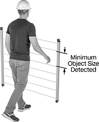
15.7" Minimum Object Size Detected | |||||||||||||||||||||||
| 31.5" | On When Object Absent | 1 to 230 | 24 | 130 | PNP/NPN | 5-Pole M12 | 8-Pole M12 | 38.2" | 1.3" | 1.5" | Painted Aluminum | Yellow | 1 | 8690N12 | 00000000 | 2 | 8690N15 | 00000 | 2 | 7774K121 | 000000 | ||
| 47.2" | On When Object Absent | 1 to 230 | 24 | 140 | PNP/NPN | 5-Pole M12 | 8-Pole M12 | 53.9" | 1.3" | 1.5" | Painted Aluminum | Yellow | 1 | 8690N14 | 00000000 | 2 | 8690N15 | 00000 | 2 | 7774K121 | 000000 | ||
19.7" Minimum Object Size Detected | |||||||||||||||||||||||
| 19.7" | On When Object Absent | 1 to 230 | 24 | 120 | PNP/NPN | 5-Pole M12 | 8-Pole M12 | 26.4" | 1.3" | 1.5" | Painted Aluminum | Yellow | 1 | 8690N11 | 00000000 | 2 | 8690N15 | 00000 | 2 | 7774K121 | 000000 | ||
|
AC Switching Current @ Voltage | DC Switching Current @ Voltage | ||||||||||||||||
|---|---|---|---|---|---|---|---|---|---|---|---|---|---|---|---|---|---|
No. of Terminals | Input Voltage, V DC | Current, amp | Voltage, V AC | Current, amp | Voltage, V DC | Max. Switching Voltage, V AC | Wire Connection | Ht. | Wd. | Dp. | For Use With | Max. System Safety Rating | Features | Each | |||
2 Circuits Controlled | |||||||||||||||||
2 Off Switch Starting Position | |||||||||||||||||
| 14 | 24 | 2 | 240 | 1.5 | 24 | 250 | Terminal Block | 4.9" | 0.69" | 4.3" | Emergency Stops, Safety Light Curtains | PLe, SIL 3, Cat. 4 | Auxiliary PNP Output, LED Indicator | 7774K73 | 0000000 | ||
4 Circuits Controlled | |||||||||||||||||
4 Off Switch Starting Position | |||||||||||||||||
| 18 | 24 | 2 | 240 | 1.5 | 24 | 250 | Terminal Block | 4.9" | 0.89" | 4.3" | Emergency Stops, Safety Light Curtains | PLe, SIL 3, Cat. 4 | Auxiliary PNP Output, LED Indicator | 7774K76 | 000000 | ||
| |||
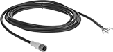
Transmitter Connectors | Receiver Connectors | Receiver Extension Cords | Transmitter and Receiver Connecting Cords |
5-Pole M12 Female | 8-Pole M12 Female |
8-Pole M12 Male |
Component | No. of Poles | Gender | Wire Connection | No. of Cords | Cable Lead Lg. | Each | ||
|---|---|---|---|---|---|---|---|---|
| Transmitter Connector | 5 | Female | Wire Leads | — | 32 1/2 ft. | 7774K52 | 000000 | |
| Receiver Connector | 8 | Female | Wire Leads | — | 32 1/2 ft. | 7774K51 | 000000 | |
| Receiver Extension Cord | 8 | Female × Male | — | — | 9 1/2 ft. | 7774K55 | 00000 | |
| Transmitter and Receiver Connecting Cords | 5, 8 | Female | — | 2 | 8" | 7774K57 | 000000 |
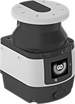
Safety Laser Scanners
 |
 |
Sensing Angle |
Light Beam Switch Operation | Input Voltage, V DC | Current Output, mA | Safety Sensing Distance Range | No. of Safety Outputs | Configurable Input/Output Sensing Distance Range | No. of Configurable Inputs/Outputs | Input/Output Digital Signal | Max. Sensing Angle | Ht. | Wd. | Dp. | Housing Material | Includes | Housing Color | Each | |||
|---|---|---|---|---|---|---|---|---|---|---|---|---|---|---|---|---|---|---|
1.2" Minimum Object Size Detected | ||||||||||||||||||
| On When Object Absent | 24 | 250 | 2" to 9.8 ft. | 1 | 2" to 131.2 ft. | 3 | PNP | 275° | 6" | 4" | 4.4" | Powder-Coated Aluminum | Downloadable Software | Yellow | 7933N11 | 000000000 | ||
| On When Object Absent | 24 | 250 | 2" to 18 ft. | 1 | 2" to 131.2 ft. | 3 | PNP | 275° | 6" | 4" | 4.4" | Powder-Coated Aluminum | Downloadable Software | Yellow | 7933N12 | 00000000 | ||
 |
Mounting Brackets |
 |
Protective Brackets |
Material | Mounting Fasteners Included | Each | ||
|---|---|---|---|---|
| Zinc-Plated Steel | Yes | 7933N22 | 000000 |
Safety Light Curtain Mirrors
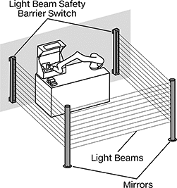 |
Frame | ||||||||||
|---|---|---|---|---|---|---|---|---|---|---|
For Max. Light Beam Ht. | Ht. | Wd. | For Use With | Mirror Material | Material | Color | Mounting Fasteners Included | Each | ||
| 15.7" | 21" | 5" | Safety Light Curtains | Glass Mirror | Painted Steel | Yellow | Yes | 8886N11 | 0000000 | |
| 19.3" | 27" | 5" | Safety Light Curtains | Glass Mirror | Painted Steel | Yellow | Yes | 8886N12 | 000000 | |
| 25.6" | 33" | 5" | Safety Light Curtains | Glass Mirror | Painted Steel | Yellow | Yes | 8886N13 | 000000 | |
| 28.7" | 39" | 5" | Safety Light Curtains | Glass Mirror | Painted Steel | Yellow | Yes | 8886N14 | 000000 | |
| 38.2" | 50" | 5" | Safety Light Curtains | Glass Mirror | Painted Steel | Yellow | Yes | 8886N15 | 000000 | |
| 53.9" | 62" | 5" | Safety Light Curtains | Glass Mirror | Painted Steel | Yellow | Yes | 8886N16 | 000000 | |
Mirrors | Replacement Stands | |||||||||||||||||
|---|---|---|---|---|---|---|---|---|---|---|---|---|---|---|---|---|---|---|
Stand | Stand Floor Mounting Holes | Floor Mounting Slots | ||||||||||||||||
For Max. Light Beam Ht. | Ht. | Wd. | For Use With | Mirror Material | Frame Material | Material | Color | Floor Mounting Fasteners Included | No. of | Hole Dia. | No. of | Lg. | Wd. | Each | Each | |||
| 35" | 52.5" | 4.3" | Safety Light Curtains | Glass Mirror | Stainless Steel | Powder-Coated Steel | Yellow | No | 3 | 7/16" | 3 | 1 3/16" | 1/2" | 8886N333 | 0000000 | 8886N17 | 0000000 | |
| 53.9" | 84" | 4.3" | Safety Light Curtains | Glass Mirror | Stainless Steel | Powder-Coated Steel | Yellow | No | 3 | 7/16" | 3 | 1 3/16" | 1/2" | 8886N777 | 000000 | 8886N18 | 000000 | |
