


Filter by
Actuator Style

Switch Action
Switch Designation
Electrical Connection
Number of Positions
Wire Connection

Illumination
Switch Starting Position
DFARS Specialty Metals
Export Control Classification Number (ECCN)
Mounting Location
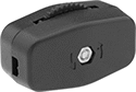
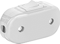
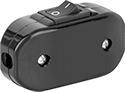
Thumb Light Switches
 |  |  |
Rotary | Rocker | Rocker with Vertical Line/Circle |
No. of Circuits Controlled | Color | Switch Action | Switch Designation | Message (Location) | Message Color | Switching Current @ Voltage | Wire Connection Method | Certification | Each | |||
|---|---|---|---|---|---|---|---|---|---|---|---|---|
Rotary Actuator | ||||||||||||
| 1 | Brown | Maintained | SPST-NO | — | — | 3 amp @ 125V AC | Snap On | UL Listed, CSA Certified | 14695K91 | 00000 | ||
Rocker Switch Actuator | ||||||||||||
| 1 | Black | Maintained | SPST-NO | Vertical Line (Top), Circle (Bottom) | White | 6 amp @ 120V AC | Snap On | UL Listed, C-UL Listed | 7798N12 | 00000 | ||
| 1 | White | Maintained | SPST-NO | — | — | 6 amp @ 120V AC | Snap On | UL Listed, C-UL Listed | 7798N11 | 00000 | ||
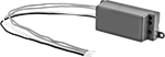
Wireless Light Switches
Vibration-Resistant 22 mm Panel-Mount Lever Switches
 |
Prevent accidental actuation from bumps—these switches require you to grip and twist the lever to turn the switch. The contact block and actuator are all one piece, so they won’t separate in high-vibration applications. Install them in a standard panel cutout.
Lever Lg. | No. of Circuits Controlled | Switch Starting Position | Switch Action | No. of Terminals | Switch Designation | Switching Current @ Voltage | Max. Voltage | Dia. | Dp. Behind Panel | Enclosure Rating | Certification | Specs. Met | Each | |||
|---|---|---|---|---|---|---|---|---|---|---|---|---|---|---|---|---|
2 Positions with Screw Terminals | ||||||||||||||||
| 1 1/8" | 1 | 1 Off | Maintained | 2 | SPST-NO | 0.6 amp @ 120V AC, 0.22 amp @ 125V DC | 240V AC 250V DC | 1 1/8" | 1 11/16" | NEMA 3, NEMA 12, IP65 | UL Listed, CSA Certified, CCC Marked, CE Marked | UL 508 | 6894N11 | 000000 | ||
Panel-Mount Set-to-the-Minute Time and Day Activated Switches
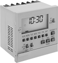 |
7-Day Timing Cycle, 2 Circuits Controlled |
Install these switches in a panel cutout. More precise than other time and day switches, they program on/off times for equipment down to the exact minute. The seven-day timing cycle can perform a different program each day of the week. All have an override to bypass the programmed on/off settings. A backup battery maintains the program during a power outage.
2 Circuits Controlled—Two-circuit switches can apply a different program to each circuit.
For Panel Cutout | ||||||||||||||||||
|---|---|---|---|---|---|---|---|---|---|---|---|---|---|---|---|---|---|---|
No. of Circuits Controlled | Switching Current @ Voltage | Input Voltage, V AC | Max. On/Off Cycles, per day | Min. Set Time, min. | Timing Adjustment Style | With Override | Switch Designation | Ht. | Wd. | Dp. | Ht. | Wd. | Wire Connection | Certification | Each | |||
7-Day Timing Cycle—With Battery Backup | ||||||||||||||||||
| 2 | 15 amp @ 250V AC | 120/240 | 20 | 1 | Push Button | Yes | SPST-NO | 2.8" | 2.8" | 2.2" | 2.68" | 2.68" | Screw Terminal | UL Recognized Component, CSA Certified | 70395K81 | 0000000 | ||
Surface/DIN-Rail Mount Set-to-the-Minute Time and Day Activated Switches
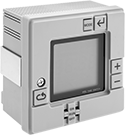 |
24-Hr. Timing Cycle |
Mount these switches to a flat surface or attach to DIN rail. More precise than other time and day switches, they program on/off times for equipment down to the exact minute. All have an override to bypass the programmed on/off settings. A backup battery maintains the program during a power outage.
24-Hr. Timing Cycle—24-hour switches repeat the same program daily. They control two circuits and can apply a different program to each circuit.
Mounting | For Panel Cutout | ||||||||||||||||||||
|---|---|---|---|---|---|---|---|---|---|---|---|---|---|---|---|---|---|---|---|---|---|
No. of Circuits Controlled | Switching Current @ Voltage | Input Voltage, V AC | Max. On/Off Cycles, per day | Min. Set Time, min. | Timing Adjustment Style | With Override | Switch Designation | Ht. | Wd. | Dp. | Fasteners Included | No. of Holes | For DIN Rail Ht., mm | Ht. | Wd. | Wire Connection | Certification | Each | |||
24-Hr. Timing Cycle—With Battery Backup | |||||||||||||||||||||
| 2 | 15 amp @ 250V AC | 120/240 | 12 | 1 | Push Button | Yes | SPST-NO | 3.8" | 3.8" | 2.2" | No | 2 | 35 | 3.62" | 3.62" | Screw Terminal | UL Recognized Component, CSA Certified | 70395K71 | 0000000 | ||
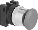
30 mm Panel-Mount Push-Button-Actuator Emergency Stop Switches
Metal Actuator Base with Screw-Terminal Wire Connection—Illuminated
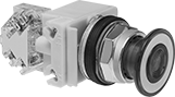 |
Pull Reset |
Illuminated switches are visible in low light. They include a bulb. If wiring the switch and the bulb to the same circuit, the circuit voltage must not exceed bulb voltage.
Pull Reset—Turn pull switches back on by pulling the button.
No. of Circuits Controlled | Switch Starting Position | Switch Action | No. of Terminals | Switch Designation | Actuator Color | Switching Current @ Voltage | Max. Voltage | Dia. | For Max. No. of Contact Blocks | Dp. Behind Panel | Choose a Bulb Voltage | Each | |||
|---|---|---|---|---|---|---|---|---|---|---|---|---|---|---|---|
Pull Reset | |||||||||||||||
| 1 | 1 Off | Maintained | 4 | SPST-NO | Red | 6 amp @ 120V AC 5 amp @ 24V DC | 600V AC 250V DC | 1 1/2" | 4 | 2 1/16" | 24V AC/24V DC, 120V AC/120V DC | 9235K36 | 0000000 | ||
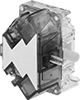 |
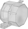
Additional contact blocks can be added to control more circuits or replace the included contact blocks.
No. of Circuits Controlled | Switch Starting Position | No. of Terminals | Switch Designation | Certification | Specs. Met | Each | ||
|---|---|---|---|---|---|---|---|---|
| 1 | 1 Off | 2 | SPST-NO | C-UL Listed, CE Marked, CSA Certified, UL Listed | EN 60947-1, EN 60947-5-1, UL 508 | 9235K382 | 000000 |
 |
Pull Reset | ||||||||
|---|---|---|---|---|---|---|---|---|
Actuator Clarity | Actuator Color | Bulb Type | Bulb Color | Choose a Bulb Voltage | Each | |||
Metal Actuator Base—Illuminated | ||||||||
| Clear | Red | LED | Red | 24V AC/24V DC, 120V AC/120V DC, 240V AC/240V DC | 9235K48 | 0000000 | ||
Bulb | ||||||||||
|---|---|---|---|---|---|---|---|---|---|---|
Voltage | Shape No. | Dia. | Overall Lg. | Bulb Material | Color | Light Tech. | Rated Life, hr. | Each | ||
| 24V AC, 24V DC | T3 1/4 | 3/8" | 1 1/8" | Plastic | Red | LED | 100,000 | 5453T171 | 000000 | |
Bulb | ||||||||||
|---|---|---|---|---|---|---|---|---|---|---|
Voltage | Shape Number | Dia. | Overall Lg. | Bulb Material | Color | Light Tech. | Rated Life, hr. | Each | ||
| 130V AC, 130V DC | T3 1/4 | 3/8" | 1 1/8" | Plastic | Red | LED | 100,000 | 5453T176 | 000000 | |
 |
For Max. Padlock Shackle Dia. | Each | ||
|---|---|---|---|
| 1/4" | 9235K368 | 000000 |
