


Choosing an Electrical Switch
More
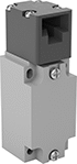
Limit Switches
When a moving object contacts the actuator on these switches, they open or close a circuit. They have the rapid-closing action of a snap-acting switch, but with a larger actuator. This makes them a good choice for use with large objects—for instance, a box on a conveyor runs into the switch, stopping the conveyor.
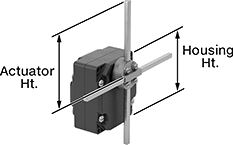
Switches with a T-rod actuator have four rods extending in different directions from a pivot point. If an object contacts any of the rods from any direction, these switches actuate. Since they have such a large actuation area, they’re great for detecting moving parts when your machine tool isn’t perfectly aligned.
Housing | Conduit | |||||||||||||||
|---|---|---|---|---|---|---|---|---|---|---|---|---|---|---|---|---|
| Style | No. of Circuits Controlled | Switch Starting Position | Switch Action | Industry Designation | Switching Current @ Voltage | Max. Voltage | Operating Temp. Range, °F | Actuator Ht. | Lg. | Ht. | Dp. | Housing Material | Thread Size | Environmental Rating | Each | |
T-Rod Actuator Style | ||||||||||||||||
With Screw Terminals | ||||||||||||||||
| G | 2 | 2 Off (Normally Open) or 2 On (Normally Closed) | Stays Switched (Maintained) | DPDT | 10 A @ 240 V AC, 250 V DC | 240V AC 250V DC | -13° to 158° | 7.9" | 3.4" | 3.7" | 2.1" | Zinc | PG-13.5 | IP54 | 00000000 | 0000000 |
Enclosed Wet-Location Snap-Acting Switches
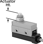
Rated IP67, these switches have an enclosure that shields their interior during temporary submersion. They open and close circuits in a snap—their quick actuation limits arcing and keeps contacts from sticking. These switches are often used to indicate an open appliance or enclosure door. You can also use them inside limit, pressure, and temperature switches. Switches with a plunger actuator require a push to actuate, similar to a button.
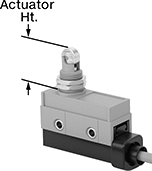
Switches with a roller plunger actuator have a roller that moves parallel to the body length when an object pushes the actuator. This reduces friction to limit wear and tear on your switch.
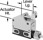
Switches with a roller lever actuator combine the larger actuation area of a standard lever with a smooth gliding roller actuator. They minimize friction to limit wear and tear on your switch.
Switches with a 4-pole micro M12 plug quickly connect and disconnect from your switch. Use cables (sold separately) to wire your switch connection to your setup.
Micro
M12 Plug
Housing | ||||||||||||||
|---|---|---|---|---|---|---|---|---|---|---|---|---|---|---|
| No. of Circuits Controlled | Switch Starting Position | Switch Action | Industry Designation | Switching Current @ Voltage | Max. Voltage | Operating Temp. Range, °F | Actuator Ht. | Lg. | Ht. | Dp. | Lever Lg. | Specifications Met | Each | |
Plunger Actuator Style for 9/16" Panel Cutout Dia. | ||||||||||||||
With 4-Pole Micro M12 Plug | ||||||||||||||
| 1 | 1 Off (Normally Open) or 1 On (Normally Closed) | Springs Back (Momentary) | SPDT | 0.1 A @ 30 V DC | 30V DC | 45° to 155° | 0.79" | 2.24" | 1.3" | 0.71" | __ | EN 60947-5-1 | 0000000 | 0000000 |
| 1 | 1 Off (Normally Open) or 1 On (Normally Closed) | Springs Back (Momentary) | SPDT | 1 A @ 30 V DC | 30V DC | 45° to 155° | 0.79" | 2.24" | 1.3" | 0.71" | __ | EN 60947-5-1 | 0000000 | 000000 |
Roller Plunger Actuator Style for 9/16" Panel Cutout Dia. | ||||||||||||||
With 4-Pole Micro M12 Plug | ||||||||||||||
| 1 | 1 Off (Normally Open) or 1 On (Normally Closed) | Springs Back (Momentary) | SPDT | 0.1 A @ 30 V DC | 30V DC | 45° to 155° | 1.06" | 2.24" | 1.3" | 0.71" | __ | EN 60947-5-1 | 0000000 | 000000 |
| 1 | 1 Off (Normally Open) or 1 On (Normally Closed) | Springs Back (Momentary) | SPDT | 1 A @ 30 V DC | 30V DC | 45° to 155° | 1.06" | 2.24" | 1.3" | 0.71" | __ | EN 60947-5-1 | 0000000 | 000000 |
Roller Lever Actuator Style | ||||||||||||||
With 4-Pole Micro M12 Plug | ||||||||||||||
| 1 | 1 Off (Normally Open) or 1 On (Normally Closed) | Springs Back (Momentary) | SPDT | 0.1 A @ 30 V DC | 30V DC | 45° to 155° | 0.73" | 2.24" | 1.3" | 0.71" | 0.79" | EN 60947-5-1 | 0000000 | 000000 |
| 1 | 1 Off (Normally Open) or 1 On (Normally Closed) | Springs Back (Momentary) | SPDT | 1 A @ 30 V DC | 30V DC | 45° to 155° | 0.73" | 2.24" | 1.3" | 0.71" | 0.79" | EN 60947-5-1 | 0000000 | 000000 |
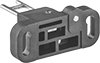
Frame-Mounted Safety Switches
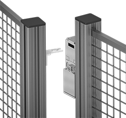
Also known as interlock switches, these ensure the safety of personnel by automatically shutting off power to machinery when an access door opens. Mount the switch to the door frame and mount a key to the door so that the key is inserted into the switch when the door is closed. When the door opens, the key is removed from the switch and the machine shuts down. They’re often used with machine guards for large robots.
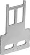
All switches require an actuator key, but not all include one—check whether you need to pick out a separate actuator key. For some switch styles, you can also select the mounting orientation of the key. Flexible keys pivot at least 15°, making them easier to align with switches during installation.
Style A-G switches have positive-force, normally closed contacts that will open a circuit when the switch is actuated even if a spring fails or the contacts stick.
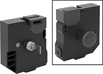
Style J switches have extra safety controls to prevent you from getting trapped next to running machinery. They actuate with the turn of a portable key. Bring the key when you enter an enclosure to ensure machinery won’t start while you’re inside, even if the door closes behind you. As an added fail-safe, a rear release button lets you cut power from inside of enclosures if needed. These switches have light-up indicators that show when they're properly installed and whether they're actuated.
IP67 rated switches protect against temporary submersion.
Housing | Conduit | ||||||||||||||||
|---|---|---|---|---|---|---|---|---|---|---|---|---|---|---|---|---|---|
| Style | No. of Circuits Controlled | Switch Starting Position | Switch Action | No. of Terminals | Industry Designation | Switching Current @ Voltage | Max. Voltage | Ht. | Wd. | Dp. | Trade Size | Thread Size | Thread Type | Key Included | Environmental Rating | Each | |
Screw Terminal Connection with Positive-Force Normally Closed Contacts | |||||||||||||||||
| D | 3 | 1 Off (Normally Open) and 2 On (Normally Closed) | Stays Switched (Maintained) | 6 | 3PST-1NO/2NC | 6 A @ 120 V AC, 0.27 A @ 24 V DC | 240V AC 250V DC | 3.8" | 1.2" | 1.2" | 1/2 | __ | NPT | Yes | IP67 | 00000000 | 000000 |
| F | 2 | 1 Off (Normally Open) and 1 On (Normally Closed) | Stays Switched (Maintained) | 4 | DPST-1NO/1NC | 2 A @ 400 V AC | 400V AC | 4.4" | 1.6" | 1.6" | __ | M20 | Metric | No | IP67 | 000000000 | 00000 |
| F | 2 | 1 Off (Normally Open) and 1 On (Normally Closed) | Stays Switched (Maintained) | 4 | DPST-1NO/1NC | 2 A @ 400 V AC | 400V AC | 4.4" | 1.6" | 1.6" | 1/2 | __ | BSPP | No | IP67 | 000000000 | 000000 |
| F | 2 | 1 Off (Normally Open) and 1 On (Normally Closed) | Stays Switched (Maintained) | 4 | DPST-1NO/1NC | 2 A @ 400 V AC | 400V AC | 4.4" | 1.6" | 1.6" | 1/2 | __ | NPT | No | IP67 | 000000000 | 000000 |
| F | 2 | 2 On (Normally Closed) | Stays Switched (Maintained) | 4 | DPST-NC | 2 A @ 400 V AC | 400V AC | 4.4" | 1.6" | 1.6" | __ | M20 | Metric | No | IP67 | 000000000 | 00000 |
| F | 2 | 2 On (Normally Closed) | Stays Switched (Maintained) | 4 | DPST-NC | 2 A @ 400 V AC | 400V AC | 4.4" | 1.6" | 1.6" | 1/2 | __ | BSPP | No | IP67 | 000000000 | 00000 |
| F | 2 | 2 On (Normally Closed) | Stays Switched (Maintained) | 4 | DPST-NC | 2 A @ 400 V AC | 400V AC | 4.4" | 1.6" | 1.6" | 1/2 | __ | NPT | No | IP67 | 000000000 | 000000 |
Screw Terminal Connection with Rear Release Button, Portable Key, and LED Status Indicator | |||||||||||||||||
| J | 6 | 2 Off (Normally Open) and 4 On (Normally Closed) | Stays Switched (Maintained) | 12 | 6PST-2NO/4NC | 3 A @ 240 V AC, 2.5 A @ 250 V DC | 240V AC 250V DC | 5.2" | 4.6" | 2.2" | __ | M20 | Metric | Yes | IP67 | 000000000 | 000000 |

O'all | |||||||
|---|---|---|---|---|---|---|---|
| Angle Range | Adjustability | Lg. | Wd. | Mounting Fasteners Included | Each | ||
Straight Keys | |||||||
| For Style F | __ | __ | 53.7 mm | 52.4 mm | No | 000000000 | 000000 |
| For Style J | __ | __ | 61.5 mm | 40 mm | No | 000000000 | 00000 |
90° Angle Keys | |||||||
| For Style J | __ | __ | 45 mm | 40 mm | No | 000000000 | 00000 |
Flexible Keys | |||||||
| For Style D | 0°-15° | Up/Down/Left/Right | 48.9 mm | 55 mm | No | 000000000 | 00000 |
| For Style F | 0°-18° | Left/Right | 80.7 mm | 40 mm | No | 000000000 | 00000 |
| For Style J | 0°-18° | Left/Right | 70 mm | 40 mm | No | 000000000 | 00000 |