


Filter by
Actuator Style

Switch Starting Position
Switch Action
Housing Material
Switch Designation
Wire Connection

Number of Circuits Controlled
Certification
Maximum Temperature
Operating Temperature
Electrical Connection Type
DFARS Specialty Metals
Export Control Classification Number (ECCN)
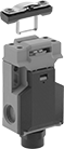
Manual-Reset Safety Limit Switches
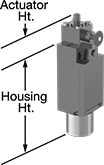 | 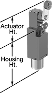 | 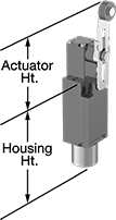 |
Style A | Style B | Style C |
Prevent equipment from automatically restarting—these switches must be manually reset each time they're actuated. Pull the knob to reset. Positive-force contacts open the circuit when actuated, even if a spring fails or the contacts stick. These switches send a signal to your circuit when an object hits the actuator—for instance, a box on a conveyor runs into the switch, stopping the conveyor. They open and close circuits as fast as snap-acting switches, but they have a bigger actuator for large objects.
Rated IP67, these switches seal out water if they’re washed down or briefly submersed.
Style B—Style B have a roller lever actuator that allows parts to glide across the actuation surface with minimal friction.
Style C—Style C have a roller lever actuator that allows parts to glide across the actuation surface with minimal friction. You can also adjust the actuator's height, making it easier to align the switch with the target during installation.
Housing | |||||||||||||||||||||||||||||||||||||||||||||||||||||||||||||||||||||||||||||||||||||||||||||||||||
|---|---|---|---|---|---|---|---|---|---|---|---|---|---|---|---|---|---|---|---|---|---|---|---|---|---|---|---|---|---|---|---|---|---|---|---|---|---|---|---|---|---|---|---|---|---|---|---|---|---|---|---|---|---|---|---|---|---|---|---|---|---|---|---|---|---|---|---|---|---|---|---|---|---|---|---|---|---|---|---|---|---|---|---|---|---|---|---|---|---|---|---|---|---|---|---|---|---|---|---|
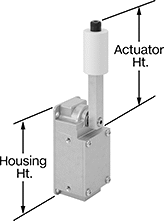
Style | No. of Circuits Controlled | Switch Starting Position | Switch Action | Switch Designation | Switching Current @ Voltage | Max. Voltage | Operating Temp. Range, ° F | Actuator Ht. | No. of Terminals | Lg. | Ht. | Dp. | Housing Material | Conduit Thread Size | Enclosure Rating | Each | |||||||||||||||||||||||||||||||||||||||||||||||||||||||||||||||||||||||||||||||||||
Plunger Actuator | |||||||||||||||||||||||||||||||||||||||||||||||||||||||||||||||||||||||||||||||||||||||||||||||||||
Screw-Terminal Wire Connection | |||||||||||||||||||||||||||||||||||||||||||||||||||||||||||||||||||||||||||||||||||||||||||||||||||
| A | 2 | 1 Off and 1 On | Maintained | DPST-1NO/1NC | 10 amp @ 240V AC, 2.5 amp @ 125V DC | 300V AC 250V DC | -22 to 158 | 1" | 4 | 1.2" | 3.4" | 1.2" | Plastic | M20 | IP67 | 0000000 | 000000 | ||||||||||||||||||||||||||||||||||||||||||||||||||||||||||||||||||||||||||||||||||
Roller Lever Actuator | |||||||||||||||||||||||||||||||||||||||||||||||||||||||||||||||||||||||||||||||||||||||||||||||||||
Screw-Terminal Wire Connection | |||||||||||||||||||||||||||||||||||||||||||||||||||||||||||||||||||||||||||||||||||||||||||||||||||
| B | 2 | 1 Off and 1 On | Maintained | DPST-1NO/1NC | 10 amp @ 240V AC, 2.5 amp @ 125V DC | 300V AC 250V DC | -22 to 158 | 2.4" | 4 | 1.2" | 3.4" | 1.2" | Plastic | M20 | IP67 | 0000000 | 00000 | ||||||||||||||||||||||||||||||||||||||||||||||||||||||||||||||||||||||||||||||||||
| C | 2 | 1 Off and 1 On | Maintained | DPST-1NO/1NC | 10 amp @ 240V AC, 2.5 amp @ 125V DC | 300V AC 250V DC | -22 to 158 | 2.1" to 3.9" | 4 | 1.2" | 3.4" | 1.2" | Plastic | M20 | IP67 | 0000000 | 000000 | ||||||||||||||||||||||||||||||||||||||||||||||||||||||||||||||||||||||||||||||||||
Build-Your-Own Limit Switches
Switches
 | |
Screw Terminal Connection | 4-Pole Micro M12 Connection |
Polypropylene Housing—Switches with a polypropylene housing are lighter in weight than metal switches.
Zinc Housing—Switches with a zinc alloy housing are more durable than those with a plastic housing.
4-Pole Micro M12 Connection—Switches with a 4-pole micro M12 plug quickly connect and disconnect from your setup. Use cords (sold separately) to wire your switch connection to your setup.
2 Conduit Connections—Switches with 2 conduit connections allow you to wire switches side by side, so you can save space and simplify your wiring.
IP65 Enclosure Rating—IP65 switches protect against dust and splashing water.
IP66 Enclosure Rating—IP66 switches protect against dust and washdowns.
IP67 Enclosure Rating—IP67 switches protect against dust and temporary submersion.
Switches | Cords | ||||||||||||||||||||||||||||||||||||||||||||||||||||||||||||||||||||||||||||||||||||||||||||||||||
|---|---|---|---|---|---|---|---|---|---|---|---|---|---|---|---|---|---|---|---|---|---|---|---|---|---|---|---|---|---|---|---|---|---|---|---|---|---|---|---|---|---|---|---|---|---|---|---|---|---|---|---|---|---|---|---|---|---|---|---|---|---|---|---|---|---|---|---|---|---|---|---|---|---|---|---|---|---|---|---|---|---|---|---|---|---|---|---|---|---|---|---|---|---|---|---|---|---|---|---|
Housing | Conduit | ||||||||||||||||||||||||||||||||||||||||||||||||||||||||||||||||||||||||||||||||||||||||||||||||||
No. of Circuits Controlled | Switch Starting Position | Switch Action | Switch Designation | Switching Current @ Voltage | Max. Voltage | No. of Terminals | Lg. | Ht. | Dp. | No. of Connections | Thread Size | Enclosure Rating | Specs. Met | Certification | Each | Each | |||||||||||||||||||||||||||||||||||||||||||||||||||||||||||||||||||||||||||||||||||
Polypropylene Housing | |||||||||||||||||||||||||||||||||||||||||||||||||||||||||||||||||||||||||||||||||||||||||||||||||||
Screw Terminal Connection | |||||||||||||||||||||||||||||||||||||||||||||||||||||||||||||||||||||||||||||||||||||||||||||||||||
| 2 | 1 Off and 1 On | Momentary | DPST-1NO/1NC | 6 amp @ 240V AC, 3 amp @ 24V DC | 400V AC 400V DC | 4 | 1.2" | 2.7" | 1.3" | 1 | M20 | IP65 | EN 50047 | UL Listed, C-UL Listed, CE Marked, CCC Marked | 0000000 | 000000 | ——— | 0 | |||||||||||||||||||||||||||||||||||||||||||||||||||||||||||||||||||||||||||||||||
| 2 | 1 Off and 1 On | Momentary | DPST-1NO/1NC | 6 amp @ 240V AC, 3 amp @ 24V DC | 400V AC 400V DC | 4 | 1.6" | 3.1" | 1.5" | 1 | M20 | IP66, IP67 | EN 50041 | UL Listed, C-UL Listed, CE Marked, CCC Marked | 0000000 | 00000 | ——— | 0 | |||||||||||||||||||||||||||||||||||||||||||||||||||||||||||||||||||||||||||||||||
| 2 | 1 Off and 1 On | Momentary | DPST-1NO/1NC | 6 amp @ 240V AC, 3 amp @ 24V DC | 400V AC 400V DC | 4 | 2" | 2.1" | 1.3" | 2 | M20 | IP66, IP67 | EN 50047 | UL Listed, C-UL Listed, CE Marked, CCC Marked | 0000000 | 000000 | ——— | 0 | |||||||||||||||||||||||||||||||||||||||||||||||||||||||||||||||||||||||||||||||||
4-Pole Micro M12 Connection | |||||||||||||||||||||||||||||||||||||||||||||||||||||||||||||||||||||||||||||||||||||||||||||||||||
| 2 | 1 Off and 1 On | Momentary | DPST-1NO/1NC | 4 amp @ 240V AC, 3 amp @ 24V DC | 250V AC 250V DC | — | 1.2" | 2.7" | 1.3" | — | — | IP65 | EN 50047 | UL Listed, C-UL Listed, CE Marked, CCC Marked | 0000000 | 000000 | 0000000 | 000000 | |||||||||||||||||||||||||||||||||||||||||||||||||||||||||||||||||||||||||||||||||
| 2 | 1 Off and 1 On | Momentary | DPST-1NO/1NC | 4 amp @ 240V AC, 3 amp @ 24V DC | 250V AC 250V DC | — | 1.6" | 3.1" | 1.5" | — | — | IP67 | EN 50041 | UL Listed, C-UL Listed, CE Marked, CCC Marked | 0000000 | 000000 | 0000000 | 00000 | |||||||||||||||||||||||||||||||||||||||||||||||||||||||||||||||||||||||||||||||||
Zinc Housing | |||||||||||||||||||||||||||||||||||||||||||||||||||||||||||||||||||||||||||||||||||||||||||||||||||
Screw Terminal Connection | |||||||||||||||||||||||||||||||||||||||||||||||||||||||||||||||||||||||||||||||||||||||||||||||||||
| 2 | 1 Off and 1 On | Momentary | DPST-1NO/1NC | 6 amp @ 240V AC, 3 amp @ 24V DC | 400V AC 400V DC | 4 | 1.2" | 2.7" | 1.3" | 1 | M20 | IP66, IP67 | EN 50047 | UL Listed, C-UL Listed, CE Marked, CCC Marked | 0000000 | 000000 | ——— | 0 | |||||||||||||||||||||||||||||||||||||||||||||||||||||||||||||||||||||||||||||||||
| 2 | 1 Off and 1 On | Momentary | DPST-1NO/1NC | 6 amp @ 240V AC, 3 amp @ 24V DC | 400V AC 400V DC | 4 | 1.6" | 3.1" | 1.4" | 1 | M20 | IP66, IP67 | EN 50041 | UL Listed, C-UL Listed, CE Marked, CCC Marked | 0000000 | 000000 | ——— | 0 | |||||||||||||||||||||||||||||||||||||||||||||||||||||||||||||||||||||||||||||||||
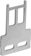
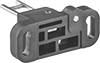
Frame-Mounted Safety Switches
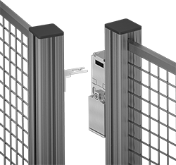 |
Key Shown Actuating from the Side |
 | 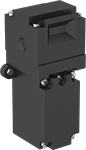 | 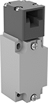 | ||
Style A | Style B | Style C | Style E | Style F |
Also known as interlock switches, these ensure the safety of personnel by automatically shutting off power to machinery when an access door opens. Mount the switch to the door frame and mount a key to the door so that the key is inserted into the switch when the door is closed. When the door opens, the key is removed from the switch and the machine shuts down. They’re often used with machine guards for large robots.
Styles A-F—Style A-G switches have positive-force, normally closed contacts that will open a circuit when the switch is actuated even if a spring fails or the contacts stick.
IP67 Enclosure Rating—IP67 rated switches protect against temporary submersion.
NEMA 4 Enclosure Rating—NEMA 4 rated switches protect against washdowns.
NEMA 6 Enclosure Rating—NEMA 6 rated switches protect against both temporary submersion and washdowns.
Key Included—All switches require an actuator key, but not all include one—check whether you need to pick out a separate actuator key. For some switch styles, you can also select the mounting orientation of the key.
Housing | Conduit | ||||||||||||||||||||||||||||||||||||||||||||||||||||||||||||||||||||||||||||||||||||||||||||||||||
|---|---|---|---|---|---|---|---|---|---|---|---|---|---|---|---|---|---|---|---|---|---|---|---|---|---|---|---|---|---|---|---|---|---|---|---|---|---|---|---|---|---|---|---|---|---|---|---|---|---|---|---|---|---|---|---|---|---|---|---|---|---|---|---|---|---|---|---|---|---|---|---|---|---|---|---|---|---|---|---|---|---|---|---|---|---|---|---|---|---|---|---|---|---|---|---|---|---|---|---|
Style | No. of Circuits Controlled | Switch Starting Position | Switch Action | No. of Terminals | Switch Designation | Switching Current @ Voltage | Max. Voltage | Ht. | Wd. | Dp. | Trade Size | Thread Size | Thread Type | Key Included | Enclosure Rating | Each | |||||||||||||||||||||||||||||||||||||||||||||||||||||||||||||||||||||||||||||||||||
Wire Lead Connection with Positive-Force Normally Closed Contacts | |||||||||||||||||||||||||||||||||||||||||||||||||||||||||||||||||||||||||||||||||||||||||||||||||||
| A | 2 | 1 Off and 1 On | Maintained | 2 | DPST-1NO/1NC | 8 amp @ 120V AC, 4 amp @ 24V DC | 250V AC 24V DC | 3.3" | 1.2" | 1.2" | — | M16 | Metric | Yes | IP67 | 00000000 | 0000000 | ||||||||||||||||||||||||||||||||||||||||||||||||||||||||||||||||||||||||||||||||||
Screw-Terminal Wire Connection with Positive-Force Normally Closed Contacts | |||||||||||||||||||||||||||||||||||||||||||||||||||||||||||||||||||||||||||||||||||||||||||||||||||
| B | 2 | 1 Off and 1 On | Maintained | 4 | DPST-1NO/1NC | 5 amp @ 120V AC, 2 amp @ 24V DC | 500V AC 250V DC | 3" | 1" | 1.1" | 1/2 | — | NPT | Yes | IP67, NEMA 6 | 00000000 | 000000 | ||||||||||||||||||||||||||||||||||||||||||||||||||||||||||||||||||||||||||||||||||
| C | 2 | 1 Off and 1 On | Maintained | 4 | DPST-1NO/1NC | 10 amp @ 120V AC, 2 amp @ 24V DC | 250V AC 24V DC | 3.6" | 2.1" | 1.3" | 1/2 | — | NPT | Yes | IP65, NEMA 4 | 00000000 | 000000 | ||||||||||||||||||||||||||||||||||||||||||||||||||||||||||||||||||||||||||||||||||
| E | 2 | 1 Off and 1 On | Maintained | 4 | DPST-1NO/1NC | 8 amp @ 230V AC, 5 amp @ 24V DC | 400V AC 24V DC | 4.2" | 2" | 1.6" | — | M20 | Metric | No | IP67 | 00000000 | 00000 | ||||||||||||||||||||||||||||||||||||||||||||||||||||||||||||||||||||||||||||||||||
| F | 2 | 1 Off and 1 On | Maintained | 4 | DPST-1NO/1NC | 2 amp @ 400V AC | 400V AC | 4.4" | 1.6" | 1.6" | — | M20 | Metric | No | IP67 | 000000000 | 000000 | ||||||||||||||||||||||||||||||||||||||||||||||||||||||||||||||||||||||||||||||||||
| F | 2 | 1 Off and 1 On | Maintained | 4 | DPST-1NO/1NC | 2 amp @ 400V AC | 400V AC | 4.4" | 1.6" | 1.6" | 1/2 | — | BSPP | No | IP67 | 000000000 | 000000 | ||||||||||||||||||||||||||||||||||||||||||||||||||||||||||||||||||||||||||||||||||
| F | 2 | 1 Off and 1 On | Maintained | 4 | DPST-1NO/1NC | 2 amp @ 400V AC | 400V AC | 4.4" | 1.6" | 1.6" | 1/2 | — | NPT | No | IP67 | 000000000 | 000000 | ||||||||||||||||||||||||||||||||||||||||||||||||||||||||||||||||||||||||||||||||||

Heavy Duty Limit Switches
 | 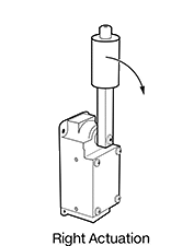 |
Rugged enough for mining operations, these limit switches require a high actuation force, like heavy rocks moving on a conveyor. They open and close a circuit as quickly as a snap-acting switch but have a larger actuator for larger objects. The roller on the end of the lever arm reduces friction to prevent wear and tear on the switch. Rated NEMA 4 and 13 as well as IP67, these switches are protected from dirt, oil spraying, and temporary submersion.
To determine if you need a right or left actuation direction, stand facing where you'll put the switch. If objects will be passing to the right, you'll need a right actuation direction. If they'll be passing to the left, you'll need a left actuation direction.
Housing | |||||||||||||||||||||||||||||||||||||||||||||||||||||||||||||||||||||||||||||||||||||||||||||||||||
|---|---|---|---|---|---|---|---|---|---|---|---|---|---|---|---|---|---|---|---|---|---|---|---|---|---|---|---|---|---|---|---|---|---|---|---|---|---|---|---|---|---|---|---|---|---|---|---|---|---|---|---|---|---|---|---|---|---|---|---|---|---|---|---|---|---|---|---|---|---|---|---|---|---|---|---|---|---|---|---|---|---|---|---|---|---|---|---|---|---|---|---|---|---|---|---|---|---|---|---|
Actuation Direction | No. of Circuits Controlled | Switch Starting Position | Switch Action | Switch Designation | Switching Current @ Voltage | Max. Voltage | Actuation Torque, in·ozf | Operating Temp. Range, ° F | Actuator Ht. | For Max. Cable OD | No. of Terminals | Lg. | Ht. | Dp. | Housing Material | Enclosure Rating | Each | ||||||||||||||||||||||||||||||||||||||||||||||||||||||||||||||||||||||||||||||||||
Roller Lever Actuator | |||||||||||||||||||||||||||||||||||||||||||||||||||||||||||||||||||||||||||||||||||||||||||||||||||
Screw-Terminal Wire Connection | |||||||||||||||||||||||||||||||||||||||||||||||||||||||||||||||||||||||||||||||||||||||||||||||||||
| Right | 2 | 1 Off and 1 On | Momentary | DPST-1NO/1NC | 20 amp @ 120V AC, 5 amp @ 120V DC | 600V AC 600V DC | 150 | -10 to 185 | 5.7" | 0.5" | 4 | 2.3" | 5" | 2" | Aluminum | NEMA 4, NEMA 13, IP67 | 0000000 | 0000000 | |||||||||||||||||||||||||||||||||||||||||||||||||||||||||||||||||||||||||||||||||
