


Filter by
Actuator Style

System of Measurement
Switching Voltage
Switch Starting Position
Switch Designation
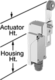
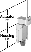
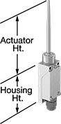
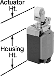
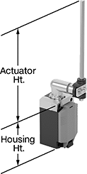
Actuator Height
Housing Material
Switch Action
Wire Connection
Certification
Conduit Trade Size
DFARS Specialty Metals
Export Control Classification Number (ECCN)
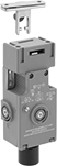
Limit Switches
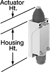 | 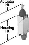 | 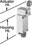 |
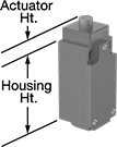
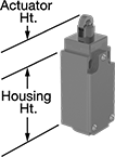
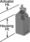
Style A | Style B | Style D |
 |  |  |
Style E | Style F | Style H |
When a moving object contacts the actuator on these switches, they open or close a circuit. They have the rapid-closing action of a snap-acting switch, but with a larger actuator. This makes them a good choice for use with large objects—for instance, a box on a conveyor runs into the switch, stopping the conveyor.
Plunger Actuator—Switches with a plunger actuator require a push to actuate, similar to a button.
Roller Plunger Actuator—Switches with a roller plunger actuator have a roller that moves when an object pushes the actuator. This reduces friction during actuation to limit wear and tear on your switch.
Roller Lever Actuator—Switches with a roller lever actuator use a lever with a roller at the end to activate. This allows parts to glide across the actuation surface with minimal friction, limiting wear and tear on your switch.
Rod Actuator—Switches with a rod actuator use a rod extending out of the body to actuate, so they’ll activate even if an object is far away.
Wobble Stick Actuator—Switches with a wobble stick actuator have an arm that rotates 360°, so you don’t need to align it in a specific direction. Since the actuator is flexible, it won’t snap if pushed backward. That makes these switches a great choice for systems that get jammed often.
Styles E and F—Styles E and F let you adjust the actuator’s height to align it with your target.
NEMA 13 Enclosure Rating—Switches rated NEMA 13 are protected against dirt and oil/coolant spraying.
IP67 Enclosure Rating—Switches rated IP67 are protected against dust and temporary submersion.
Housing | |||||||||||||||||||||||||||||||||||||||||||||||||||||||||||||||||||||||||||||||||||||||||||||||||||
|---|---|---|---|---|---|---|---|---|---|---|---|---|---|---|---|---|---|---|---|---|---|---|---|---|---|---|---|---|---|---|---|---|---|---|---|---|---|---|---|---|---|---|---|---|---|---|---|---|---|---|---|---|---|---|---|---|---|---|---|---|---|---|---|---|---|---|---|---|---|---|---|---|---|---|---|---|---|---|---|---|---|---|---|---|---|---|---|---|---|---|---|---|---|---|---|---|---|---|---|
Style | No. of Circuits Controlled | Switch Starting Position | Switch Action | Switch Designation | Switching Current @ Voltage | Max. Voltage | Actuation Torque, in·ozf | Operating Temp. Range, ° F | Actuator Ht. | No. of Terminals | Lg. | Ht. | Dp. | Housing Material | Conduit Trade Size | Enclosure Rating | Each | ||||||||||||||||||||||||||||||||||||||||||||||||||||||||||||||||||||||||||||||||||
Plunger Actuator | |||||||||||||||||||||||||||||||||||||||||||||||||||||||||||||||||||||||||||||||||||||||||||||||||||
Screw-Terminal Wire Connection | |||||||||||||||||||||||||||||||||||||||||||||||||||||||||||||||||||||||||||||||||||||||||||||||||||
| A | 1 | 1 Off or 1 On | Momentary | SPDT | 10 amp @ 240V AC, 10 amp @ 24V DC | 600V AC 250V DC | — | 10 to 200 | 0.8" | 4 | 1.9" | 4.5" | 1.8" | Zinc | 1/2 | NEMA 6P, NEMA 13, IP66, IP67 | 00000000 | 0000000 | |||||||||||||||||||||||||||||||||||||||||||||||||||||||||||||||||||||||||||||||||
| A | 1 | 1 Off or 1 On | Momentary | SPDT | 10 amp @ 300V AC, 6 amp @ 24V DC | 300V AC 250V DC | — | 14 to 176 | 1.1" | 4 | 1.6" | 2.7" | 1.6" | Aluminum | 1/2 | IP67 | 0000000 | 00000 | |||||||||||||||||||||||||||||||||||||||||||||||||||||||||||||||||||||||||||||||||
| A | 2 | 2 Off or 2 On | Momentary | DPDT | 5 amp @ 240V AC, 10 amp @ 24V DC | 600V AC 250V DC | — | 10 to 200 | 0.8" | 8 | 1.9" | 4.5" | 1.8" | Zinc | 1/2 | NEMA 6P, NEMA 13, IP66, IP67 | 00000000 | 000000 | |||||||||||||||||||||||||||||||||||||||||||||||||||||||||||||||||||||||||||||||||
Roller Plunger Actuator | |||||||||||||||||||||||||||||||||||||||||||||||||||||||||||||||||||||||||||||||||||||||||||||||||||
Screw-Terminal Wire Connection | |||||||||||||||||||||||||||||||||||||||||||||||||||||||||||||||||||||||||||||||||||||||||||||||||||
| B | 1 | 1 Off or 1 On | Momentary | SPDT | 10 amp @ 300V AC, 6 amp @ 24V DC | 300V AC 250V DC | — | 14 to 176 | 1.6" | 4 | 1.6" | 2.7" | 1.6" | Aluminum | 1/2 | IP67 | 0000000 | 000000 | |||||||||||||||||||||||||||||||||||||||||||||||||||||||||||||||||||||||||||||||||
Roller Lever Actuator | |||||||||||||||||||||||||||||||||||||||||||||||||||||||||||||||||||||||||||||||||||||||||||||||||||
Screw-Terminal Wire Connection | |||||||||||||||||||||||||||||||||||||||||||||||||||||||||||||||||||||||||||||||||||||||||||||||||||
| D | 1 | 1 Off or 1 On | Momentary | SPDT | 10 amp @ 240V AC, 10 amp @ 24V DC | 600V AC 250V DC | — | 10 to 250 | 1.2" | 4 | 1.9" | 4.5" | 1.8" | Zinc | 1/2 | NEMA 6P, NEMA 13, IP66, IP67 | 00000000 | 000000 | |||||||||||||||||||||||||||||||||||||||||||||||||||||||||||||||||||||||||||||||||
| D | 1 | 1 Off or 1 On | Momentary | SPDT | 10 amp @ 300V AC, 6 amp @ 24V DC | 300V AC 250V DC | 48 | 14 to 176 | 2.2" | 4 | 1.6" | 2.7" | 1.6" | Aluminum | 1/2 | IP67 | 0000000 | 000000 | |||||||||||||||||||||||||||||||||||||||||||||||||||||||||||||||||||||||||||||||||
| D | 2 | 2 Off or 2 On | Momentary | DPDT | 5 amp @ 240V AC, 10 amp @ 24V DC | 600V AC 250V DC | — | 10 to 250 | 1.2" | 8 | 1.9" | 4.5" | 1.8" | Zinc | 1/2 | NEMA 6P, NEMA 13, IP66, IP67 | 00000000 | 000000 | |||||||||||||||||||||||||||||||||||||||||||||||||||||||||||||||||||||||||||||||||
| E | 1 | 1 Off or 1 On | Momentary | SPDT | 10 amp @ 240V AC, 10 amp @ 24V DC | 600V AC 250V DC | — | 10 to 250 | 1.2" to 3.3" | 4 | 1.9" | 4.5" | 1.8" | Zinc | 1/2 | NEMA 6P, NEMA 13, IP66, IP67 | 00000000 | 000000 | |||||||||||||||||||||||||||||||||||||||||||||||||||||||||||||||||||||||||||||||||
| E | 1 | 1 Off or 1 On | Momentary | SPDT | 10 amp @ 300V AC, 6 amp @ 24V DC | 300V AC 250V DC | 48 | 14 to 176 | 1.7" to 4.2" | 4 | 1.6" | 2.7" | 1.6" | Aluminum | 1/2 | IP67 | 0000000 | 000000 | |||||||||||||||||||||||||||||||||||||||||||||||||||||||||||||||||||||||||||||||||
| E | 2 | 2 Off or 2 On | Momentary | DPDT | 5 amp @ 240V AC, 10 amp @ 24V DC | 600V AC 250V DC | — | 10 to 250 | 1.2" to 3.3" | 8 | 1.9" | 4.5" | 1.8" | Zinc | 1/2 | NEMA 6P, NEMA 13, IP66, IP67 | 00000000 | 000000 | |||||||||||||||||||||||||||||||||||||||||||||||||||||||||||||||||||||||||||||||||
Rod Actuator | |||||||||||||||||||||||||||||||||||||||||||||||||||||||||||||||||||||||||||||||||||||||||||||||||||
Screw-Terminal Wire Connection | |||||||||||||||||||||||||||||||||||||||||||||||||||||||||||||||||||||||||||||||||||||||||||||||||||
| F | 1 | 1 Off or 1 On | Momentary | SPDT | 10 amp @ 240V AC, 10 amp @ 24V DC | 600V AC 250V DC | — | 10 to 250 | 0.5" to 4.3" | 4 | 1.9" | 4.5" | 1.8" | Zinc | 1/2 | NEMA 6P, NEMA 13, IP66, IP67 | 00000000 | 000000 | |||||||||||||||||||||||||||||||||||||||||||||||||||||||||||||||||||||||||||||||||
| F | 1 | 1 Off or 1 On | Momentary | SPDT | 10 amp @ 300V AC, 6 amp @ 24V DC | 300V AC 250V DC | 50.6 | 14 to 176 | 1.4" to 5.9" | 4 | 1.6" | 2.7" | 1.6" | Aluminum | 1/2 | IP67 | 0000000 | 000000 | |||||||||||||||||||||||||||||||||||||||||||||||||||||||||||||||||||||||||||||||||
| F | 2 | 2 Off or 2 On | Momentary | DPDT | 5 amp @ 240V AC, 10 amp @ 24V DC | 600V AC 250V DC | — | 10 to 250 | 0.5" to 11.8" | 8 | 1.9" | 4.5" | 1.8" | Zinc | 1/2 | NEMA 6P, NEMA 13, IP66, IP67 | 00000000 | 000000 | |||||||||||||||||||||||||||||||||||||||||||||||||||||||||||||||||||||||||||||||||
Wobble Stick Actuator | |||||||||||||||||||||||||||||||||||||||||||||||||||||||||||||||||||||||||||||||||||||||||||||||||||
Screw-Terminal Wire Connection | |||||||||||||||||||||||||||||||||||||||||||||||||||||||||||||||||||||||||||||||||||||||||||||||||||
| H | 1 | 1 Off or 1 On | Momentary | SPDT | 10 amp @ 240V AC, 10 amp @ 24V DC | 600V AC 250V DC | — | 10 to 200 | 4.5" | 4 | 1.9" | 4.5" | 1.8" | Zinc | 1/2 | NEMA 6P, NEMA 13, IP66, IP67 | 00000000 | 000000 | |||||||||||||||||||||||||||||||||||||||||||||||||||||||||||||||||||||||||||||||||
| H | 1 | 1 Off or 1 On | Momentary | SPDT | 10 amp @ 300V AC, 6 amp @ 24V DC | 300V AC 250V DC | — | 14 to 176 | 5.3" | 4 | 1.6" | 2.7" | 1.6" | Aluminum | 1/2 | IP67 | 0000000 | 000000 | |||||||||||||||||||||||||||||||||||||||||||||||||||||||||||||||||||||||||||||||||
| H | 2 | 2 Off or 2 On | Momentary | DPDT | 5 amp @ 240V AC, 10 amp @ 24V DC | 600V AC 250V DC | — | 10 to 200 | 4.5" | 8 | 1.9" | 4.5" | 1.8" | Zinc | 1/2 | NEMA 6P, NEMA 13, IP66, IP67 | 00000000 | 000000 | |||||||||||||||||||||||||||||||||||||||||||||||||||||||||||||||||||||||||||||||||
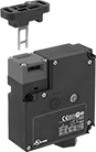
Safety Limit Switches
 |  |
Style C | Style F |
Protect machinery and ensure the safety of personnel—these switches have positive-force contacts that will open the circuit when actuated even if a spring fails or the contacts stick. When an object in motion comes into contact with the actuator, it sends a signal to open or close a circuit. These switches have the rapid-closing action of a snap-acting switch, but with a larger actuator. This makes them a good choice for use with large objects—for instance, a box on a conveyor runs into the switch, stopping the conveyor.
Roller Lever Actuator—Switches with a roller lever actuator use a lever with a roller at the end to activate. This allows parts to glide across the actuation surface with minimal friction, limiting wear and tear on your switch.
Rod Actuator—Switches with a rod actuator use a rod extending out of the body to actuate, so they’ll activate even if an object is far away.
Style F—Styles D, E, and F have an actuator that allows you to adjust its height, making it easier to align switch with the target during installation.
Plastic Actuator—Switches with a plastic actuator limit wear and tear on passing objects better than switches with a steel actuator.
Steel Actuator—Switches with a steel actuator are more durable than switches with a plastic actuator. They also handle higher loads.
Housing | |||||||||||||||||||||||||||||||||||||||||||||||||||||||||||||||||||||||||||||||||||||||||||||||||||
|---|---|---|---|---|---|---|---|---|---|---|---|---|---|---|---|---|---|---|---|---|---|---|---|---|---|---|---|---|---|---|---|---|---|---|---|---|---|---|---|---|---|---|---|---|---|---|---|---|---|---|---|---|---|---|---|---|---|---|---|---|---|---|---|---|---|---|---|---|---|---|---|---|---|---|---|---|---|---|---|---|---|---|---|---|---|---|---|---|---|---|---|---|---|---|---|---|---|---|---|
Style | No. of Circuits Controlled | Switch Starting Position | Switch Action | Switch Designation | Actuator Material | Switching Current @ Voltage | Max. Voltage | Actuation Torque, in·ozf | Operating Temp. Range, ° F | Actuator Ht. | No. of Terminals | Lg. | Ht. | Dp. | Housing Material | Conduit Thread Size | Enclosure Rating | Each | |||||||||||||||||||||||||||||||||||||||||||||||||||||||||||||||||||||||||||||||||
Roller Lever Actuator | |||||||||||||||||||||||||||||||||||||||||||||||||||||||||||||||||||||||||||||||||||||||||||||||||||
Screw-Terminal Wire Connection | |||||||||||||||||||||||||||||||||||||||||||||||||||||||||||||||||||||||||||||||||||||||||||||||||||
| C | 1 | 1 Off or 1 On | Momentary | SPDT | Plastic | 3 amp @ 240V AC, 1.5 amp @ 24V DC | 240V AC 24V DC | — | -22 to 165 | 1.5" | 4 | 1.7" | 2.9" | 1.6" | Plastic | M20 | NEMA 4X, IP66, IP67 | 00000000 | 0000000 | ||||||||||||||||||||||||||||||||||||||||||||||||||||||||||||||||||||||||||||||||
Rod Actuator | |||||||||||||||||||||||||||||||||||||||||||||||||||||||||||||||||||||||||||||||||||||||||||||||||||
Screw-Terminal Wire Connection | |||||||||||||||||||||||||||||||||||||||||||||||||||||||||||||||||||||||||||||||||||||||||||||||||||
| F | 1 | 1 Off or 1 On | Momentary | SPDT | Steel | 3 amp @ 240V AC, 1.5 amp @ 24V DC | 240V AC 24V DC | 24.8 | -22 to 165 | 0.5" to 8" | 4 | 1.7" | 2.9" | 1.6" | Plastic | M20 | NEMA 4X, IP66, IP67 | 00000000 | 000000 | ||||||||||||||||||||||||||||||||||||||||||||||||||||||||||||||||||||||||||||||||
Compact Safety Limit Switches
 |  |  |
Style A | Style B | Style C |
Shorter and thinner than other safety limit switches, these are sized to fit tight spaces. They protect machinery and ensure the safety of personnel. Positive-force contacts open the circuit when actuated, even if a spring fails or the contacts stick. They send a signal to your circuit when an object hits the actuator—for instance, a box on a conveyor runs into the switch, stopping the conveyor. They open and close circuits as fast as snap-acting switches, but they have a bigger actuator for large objects. All are NEMA and IP rated for protection from washdowns.
Plunger Actuator—Switches with a plunger actuator require a push to actuate, similar to a button.
Roller Plunger Actuator—Switches with a roller plunger actuator have a roller that moves parallel to the mounting direction when an object pushes the actuator. This reduces friction during actuation to limit wear and tear on your switch.
Roller Lever Actuator—Switches with a roller lever actuator use a lever with a roller at the end to activate. This allows parts to glide across the actuation surface with minimal friction, limiting wear and tear.
Housing | |||||||||||||||||||||||||||||||||||||||||||||||||||||||||||||||||||||||||||||||||||||||||||||||||||
|---|---|---|---|---|---|---|---|---|---|---|---|---|---|---|---|---|---|---|---|---|---|---|---|---|---|---|---|---|---|---|---|---|---|---|---|---|---|---|---|---|---|---|---|---|---|---|---|---|---|---|---|---|---|---|---|---|---|---|---|---|---|---|---|---|---|---|---|---|---|---|---|---|---|---|---|---|---|---|---|---|---|---|---|---|---|---|---|---|---|---|---|---|---|---|---|---|---|---|---|
Style | No. of Circuits Controlled | Switch Starting Position | Switch Action | Switch Designation | Switching Current @ Voltage | Max. Voltage | Operating Temp. Range, ° F | Actuator Ht. | No. of Terminals | Lg. | Ht. | Dp. | Housing Material | Conduit Thread Size | Enclosure Rating | Each | |||||||||||||||||||||||||||||||||||||||||||||||||||||||||||||||||||||||||||||||||||
Plunger Actuator | |||||||||||||||||||||||||||||||||||||||||||||||||||||||||||||||||||||||||||||||||||||||||||||||||||
Screw-Terminal Wire Connection | |||||||||||||||||||||||||||||||||||||||||||||||||||||||||||||||||||||||||||||||||||||||||||||||||||
| A | 1 | 1 Off or 1 On | Momentary | SPDT | 10 amp @ 240V AC, 4 amp @ 24V DC | 240V AC 24V DC | -22 to 176 | 0.5" | 4 | 1.2" | 2.4" | 1.2" | Plastic | M20 | NEMA 4, IP65 | 00000000 | 0000000 | ||||||||||||||||||||||||||||||||||||||||||||||||||||||||||||||||||||||||||||||||||
Roller Plunger Actuator | |||||||||||||||||||||||||||||||||||||||||||||||||||||||||||||||||||||||||||||||||||||||||||||||||||
Screw-Terminal Wire Connection | |||||||||||||||||||||||||||||||||||||||||||||||||||||||||||||||||||||||||||||||||||||||||||||||||||
| B | 1 | 1 Off or 1 On | Momentary | SPDT | 10 amp @ 240V AC, 4 amp @ 24V DC | 240V AC 24V DC | -22 to 176 | 1.2" | 4 | 1.2" | 2.4" | 1.2" | Plastic | M20 | NEMA 4, IP65 | 00000000 | 000000 | ||||||||||||||||||||||||||||||||||||||||||||||||||||||||||||||||||||||||||||||||||
Roller Lever Actuator | |||||||||||||||||||||||||||||||||||||||||||||||||||||||||||||||||||||||||||||||||||||||||||||||||||
Screw-Terminal Wire Connection | |||||||||||||||||||||||||||||||||||||||||||||||||||||||||||||||||||||||||||||||||||||||||||||||||||
| C | 1 | 1 Off or 1 On | Momentary | SPDT | 10 amp @ 240V AC, 4 amp @ 24V DC | 240V AC 24V DC | -22 to 176 | 1.1" | 4 | 1.2" | 2.4" | 1.2" | Plastic | M20 | NEMA 4, IP65 | 00000000 | 000000 | ||||||||||||||||||||||||||||||||||||||||||||||||||||||||||||||||||||||||||||||||||
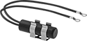
Build-Your-Own Limit Switches
Switches
 |  | |
Screw Terminal Connection | Screw Terminal Connection—LED Power Indicator and LED Status Indicator | 4-Pole Micro M12 Connection |
Polypropylene Housing—Switches with a polypropylene housing are lighter in weight than metal switches.
Zinc Housing—Switches with a zinc alloy housing are more durable than those with a plastic housing.
LED Power Indicator and LED Status Indicator—Switches with an LED power indicator and LED status indicator show you the status of the line and load phases. They give you extra assurance that your switch is connected and wired correctly.
4-Pole Micro M12 Connection—Switches with a 4-pole micro M12 plug quickly connect and disconnect from your setup. Use cords (sold separately) to wire your switch connection to your setup.
2 Conduit Connections—Switches with 2 conduit connections allow you to wire switches side by side, so you can save space and simplify your wiring.
IP65 Enclosure Rating—IP65 switches protect against dust and splashing water.
IP66 Enclosure Rating—IP66 switches protect against dust and washdowns.
IP67 Enclosure Rating—IP67 switches protect against dust and temporary submersion.
Switches | Cords | ||||||||||||||||||||||||||||||||||||||||||||||||||||||||||||||||||||||||||||||||||||||||||||||||||
|---|---|---|---|---|---|---|---|---|---|---|---|---|---|---|---|---|---|---|---|---|---|---|---|---|---|---|---|---|---|---|---|---|---|---|---|---|---|---|---|---|---|---|---|---|---|---|---|---|---|---|---|---|---|---|---|---|---|---|---|---|---|---|---|---|---|---|---|---|---|---|---|---|---|---|---|---|---|---|---|---|---|---|---|---|---|---|---|---|---|---|---|---|---|---|---|---|---|---|---|
Housing | Conduit | ||||||||||||||||||||||||||||||||||||||||||||||||||||||||||||||||||||||||||||||||||||||||||||||||||
No. of Circuits Controlled | Switch Starting Position | Switch Action | Switch Designation | Switching Current @ Voltage | Max. Voltage | No. of Terminals | Lg. | Ht. | Dp. | No. of Connections | Thread Size | Enclosure Rating | Specs. Met | Certification | Each | Each | |||||||||||||||||||||||||||||||||||||||||||||||||||||||||||||||||||||||||||||||||||
Polypropylene Housing | |||||||||||||||||||||||||||||||||||||||||||||||||||||||||||||||||||||||||||||||||||||||||||||||||||
Screw Terminal Connection | |||||||||||||||||||||||||||||||||||||||||||||||||||||||||||||||||||||||||||||||||||||||||||||||||||
| 2 | 1 Off and 1 On | Momentary | DPST-1NO/1NC | 6 amp @ 240V AC, 3 amp @ 24V DC | 400V AC 400V DC | 4 | 1.2" | 2.7" | 1.3" | 1 | M20 | IP65 | EN 50047 | UL Listed, C-UL Listed, CE Marked, CCC Marked | 0000000 | 000000 | ——— | 0 | |||||||||||||||||||||||||||||||||||||||||||||||||||||||||||||||||||||||||||||||||
| 2 | 1 Off and 1 On | Momentary | DPST-1NO/1NC | 6 amp @ 240V AC, 3 amp @ 24V DC | 400V AC 400V DC | 4 | 1.6" | 3.1" | 1.5" | 1 | M20 | IP66, IP67 | EN 50041 | UL Listed, C-UL Listed, CE Marked, CCC Marked | 0000000 | 00000 | ——— | 0 | |||||||||||||||||||||||||||||||||||||||||||||||||||||||||||||||||||||||||||||||||
| 2 | 1 Off and 1 On | Momentary | DPST-1NO/1NC | 6 amp @ 240V AC, 3 amp @ 24V DC | 400V AC 400V DC | 4 | 2" | 2.1" | 1.3" | 2 | M20 | IP66, IP67 | EN 50047 | UL Listed, C-UL Listed, CE Marked, CCC Marked | 0000000 | 000000 | ——— | 0 | |||||||||||||||||||||||||||||||||||||||||||||||||||||||||||||||||||||||||||||||||
Screw Terminal Connection—LED Power Indicator and LED Status Indicator | |||||||||||||||||||||||||||||||||||||||||||||||||||||||||||||||||||||||||||||||||||||||||||||||||||
| 3 | 1 Off and 2 On | Momentary | 3PST-1NO/2NC | 3 amp @ 24V DC | 24V DC | 6 | 1.2" | 2.7" | 1.3" | 1 | M20 | IP65 | EN 50047 | UL Listed, C-UL Listed, CE Marked, CCC Marked | 0000000 | 000000 | ——— | 0 | |||||||||||||||||||||||||||||||||||||||||||||||||||||||||||||||||||||||||||||||||
| 3 | 1 Off and 2 On | Momentary | 3PST-1NO/2NC | 3 amp @ 24V DC | 24V DC | 6 | 1.6" | 3.1" | 1.5" | 1 | M20 | IP66, IP67 | EN 50041 | UL Listed, C-UL Listed, CE Marked, CCC Marked | 0000000 | 000000 | ——— | 0 | |||||||||||||||||||||||||||||||||||||||||||||||||||||||||||||||||||||||||||||||||
4-Pole Micro M12 Connection | |||||||||||||||||||||||||||||||||||||||||||||||||||||||||||||||||||||||||||||||||||||||||||||||||||
| 2 | 1 Off and 1 On | Momentary | DPST-1NO/1NC | 4 amp @ 240V AC, 3 amp @ 24V DC | 250V AC 250V DC | — | 1.2" | 2.7" | 1.3" | — | — | IP65 | EN 50047 | UL Listed, C-UL Listed, CE Marked, CCC Marked | 0000000 | 000000 | 0000000 | 000000 | |||||||||||||||||||||||||||||||||||||||||||||||||||||||||||||||||||||||||||||||||
| 2 | 1 Off and 1 On | Momentary | DPST-1NO/1NC | 4 amp @ 240V AC, 3 amp @ 24V DC | 250V AC 250V DC | — | 1.6" | 3.1" | 1.5" | — | — | IP67 | EN 50041 | UL Listed, C-UL Listed, CE Marked, CCC Marked | 0000000 | 000000 | 0000000 | 00000 | |||||||||||||||||||||||||||||||||||||||||||||||||||||||||||||||||||||||||||||||||
Zinc Housing | |||||||||||||||||||||||||||||||||||||||||||||||||||||||||||||||||||||||||||||||||||||||||||||||||||
Screw Terminal Connection | |||||||||||||||||||||||||||||||||||||||||||||||||||||||||||||||||||||||||||||||||||||||||||||||||||
| 2 | 1 Off and 1 On | Momentary | DPST-1NO/1NC | 6 amp @ 240V AC, 3 amp @ 24V DC | 400V AC 400V DC | 4 | 1.2" | 2.7" | 1.3" | 1 | M20 | IP66, IP67 | EN 50047 | UL Listed, C-UL Listed, CE Marked, CCC Marked | 0000000 | 000000 | ——— | 0 | |||||||||||||||||||||||||||||||||||||||||||||||||||||||||||||||||||||||||||||||||
| 2 | 1 Off and 1 On | Momentary | DPST-1NO/1NC | 6 amp @ 240V AC, 3 amp @ 24V DC | 400V AC 400V DC | 4 | 1.6" | 3.1" | 1.4" | 1 | M20 | IP66, IP67 | EN 50041 | UL Listed, C-UL Listed, CE Marked, CCC Marked | 0000000 | 000000 | ——— | 0 | |||||||||||||||||||||||||||||||||||||||||||||||||||||||||||||||||||||||||||||||||
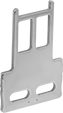
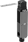
Frame-Mounted Safety Switches
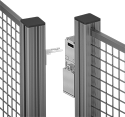 |
Key Shown Actuating from the Side |
 |  |  | |||
Style A | Style B | Style C | Style D | Style E | Style G |
Housing | Conduit | ||||||||||||||||||||||||||||||||||||||||||||||||||||||||||||||||||||||||||||||||||||||||||||||||||
|---|---|---|---|---|---|---|---|---|---|---|---|---|---|---|---|---|---|---|---|---|---|---|---|---|---|---|---|---|---|---|---|---|---|---|---|---|---|---|---|---|---|---|---|---|---|---|---|---|---|---|---|---|---|---|---|---|---|---|---|---|---|---|---|---|---|---|---|---|---|---|---|---|---|---|---|---|---|---|---|---|---|---|---|---|---|---|---|---|---|---|---|---|---|---|---|---|---|---|---|
Style | No. of Circuits Controlled | Switch Starting Position | Switch Action | No. of Terminals | Switch Designation | Switching Current @ Voltage | Max. Voltage | Ht. | Wd. | Dp. | Trade Size | Thread Size | Thread Type | Key Included | Enclosure Rating | Each | |||||||||||||||||||||||||||||||||||||||||||||||||||||||||||||||||||||||||||||||||||
Wire Lead Connection with Positive-Force Normally Closed Contacts | |||||||||||||||||||||||||||||||||||||||||||||||||||||||||||||||||||||||||||||||||||||||||||||||||||
| A | 2 | 1 Off and 1 On | Maintained | 2 | DPST-1NO/1NC | 8 amp @ 120V AC, 4 amp @ 24V DC | 250V AC 24V DC | 3.3" | 1.2" | 1.2" | — | M16 | Metric | Yes | IP67 | 00000000 | 0000000 | ||||||||||||||||||||||||||||||||||||||||||||||||||||||||||||||||||||||||||||||||||
Screw-Terminal Wire Connection with Positive-Force Normally Closed Contacts | |||||||||||||||||||||||||||||||||||||||||||||||||||||||||||||||||||||||||||||||||||||||||||||||||||
| B | 2 | 1 Off and 1 On | Maintained | 4 | DPST-1NO/1NC | 5 amp @ 120V AC, 2 amp @ 24V DC | 500V AC 250V DC | 3" | 1" | 1.1" | 1/2 | — | NPT | Yes | IP67, NEMA 6 | 00000000 | 000000 | ||||||||||||||||||||||||||||||||||||||||||||||||||||||||||||||||||||||||||||||||||
| C | 2 | 1 Off and 1 On | Maintained | 4 | DPST-1NO/1NC | 10 amp @ 120V AC, 2 amp @ 24V DC | 250V AC 24V DC | 3.6" | 2.1" | 1.3" | 1/2 | — | NPT | Yes | IP65, NEMA 4 | 00000000 | 000000 | ||||||||||||||||||||||||||||||||||||||||||||||||||||||||||||||||||||||||||||||||||
| C | 3 | 1 Off and 2 On | Maintained | 3 | 3PST-1NO/2NC | 8 amp @ 120V AC, 4 amp @ 24V DC | 600V AC 250V DC | 3.5" | 2.1" | 1.2" | 1/2 | — | NPT | Yes | IP67 | 00000000 | 000000 | ||||||||||||||||||||||||||||||||||||||||||||||||||||||||||||||||||||||||||||||||||
| C | 3 | 1 Off and 2 On | Maintained | 6 | 3PST-1NO/2NC | 4 amp @ 230V AC, 4 amp @ 24V DC | 500V AC 24V DC | 3.5" | 2" | 1.2" | — | M16 | Metric | Yes | IP67 | 00000000 | 000000 | ||||||||||||||||||||||||||||||||||||||||||||||||||||||||||||||||||||||||||||||||||
| D | 3 | 1 Off and 2 On | Maintained | 6 | 3PST-1NO/2NC | 6 amp @ 120V AC, 0.27 amp @ 24V DC | 240V AC 250V DC | 3.8" | 1.2" | 1.2" | 1/2 | — | NPT | Yes | IP67 | 00000000 | 00000 | ||||||||||||||||||||||||||||||||||||||||||||||||||||||||||||||||||||||||||||||||||
| E | 2 | 1 Off and 1 On | Maintained | 4 | DPST-1NO/1NC | 8 amp @ 230V AC, 5 amp @ 24V DC | 400V AC 24V DC | 4.2" | 2" | 1.6" | — | M20 | Metric | No | IP67 | 00000000 | 00000 | ||||||||||||||||||||||||||||||||||||||||||||||||||||||||||||||||||||||||||||||||||
| E | 2 | 2 On | Maintained | 4 | DPST-NC | 8 amp @ 230V AC, 5 amp @ 24V DC | 400V AC 24V DC | 4.2" | 2" | 1.6" | — | M20 | Metric | No | IP67 | 00000000 | 00000 | ||||||||||||||||||||||||||||||||||||||||||||||||||||||||||||||||||||||||||||||||||
Screw-Terminal Wire Connection with Positive-Force Normally Closed Contacts and Rotating Head | |||||||||||||||||||||||||||||||||||||||||||||||||||||||||||||||||||||||||||||||||||||||||||||||||||
| C | 3 | 1 Off and 2 On | Maintained | 6 | 3PST-1NO/2NC | 5 amp @ 120V AC, 5 amp @ 24V DC | 400V AC 400V DC | 3.5" | 2" | 1.3" | 1/2 | — | NPT | Yes | IP65 | 00000000 | 000000 | ||||||||||||||||||||||||||||||||||||||||||||||||||||||||||||||||||||||||||||||||||
| G | 3 | 1 Off and 2 On | Maintained | 6 | 3PST-1NO/2NC | 10 amp @ 230V AC, 4 amp @ 24V DC | 250V AC 24V DC | 4.3" | 1.6" | 1.4" | — | M20 | Metric | No | IP67 | 00000000 | 000000 | ||||||||||||||||||||||||||||||||||||||||||||||||||||||||||||||||||||||||||||||||||
 |  |  |
Straight | 90° Angle | Flexible |
Tilt Switches
 | 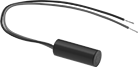 |
Style A | Style B |
Often used as position indicators, pump level controls, and machine limit switches, these switches actuate when tilted to a certain angle. They mount horizontally and activate when tilted downward, and deactivate when tilted up. All combine electromechanical and solid state technologies for reliability and long life.
Differential Angle—Differential angle is the total angle from the point of activation to the point of deactivation.
Style | No. of Circuits Controlled | Switch Starting Position | Switch Designation | Switching Current @ Voltage | Max. Voltage | Differential Angle | No. of Wire Leads | Dia. | Lg. | Housing Material | Enclosure Rating | Each | |||||||||||||||||||||||||||||||||||||||||||||||||||||||||||||||||||||||||||||||||||||||
|---|---|---|---|---|---|---|---|---|---|---|---|---|---|---|---|---|---|---|---|---|---|---|---|---|---|---|---|---|---|---|---|---|---|---|---|---|---|---|---|---|---|---|---|---|---|---|---|---|---|---|---|---|---|---|---|---|---|---|---|---|---|---|---|---|---|---|---|---|---|---|---|---|---|---|---|---|---|---|---|---|---|---|---|---|---|---|---|---|---|---|---|---|---|---|---|---|---|---|---|
Ring-Terminal Wire Connection | |||||||||||||||||||||||||||||||||||||||||||||||||||||||||||||||||||||||||||||||||||||||||||||||||||
| A | 1 | 1 Off | SPST-NO | 0.1 amp @ 120V AC, 0.25 amp @ 24V DC | 60V DC/120V AC | 15° | 2 | 0.53" | 1.88" | Plastic | NEMA 4, IP67 | 000000 | 000000 | ||||||||||||||||||||||||||||||||||||||||||||||||||||||||||||||||||||||||||||||||||||||
Wire Lead Connection | |||||||||||||||||||||||||||||||||||||||||||||||||||||||||||||||||||||||||||||||||||||||||||||||||||
| B | 1 | 1 Off | SPST-NO | 20 amp @ 24V DC | 40V DC | 10° | 2 | 0.75" | 2" | Plastic | NEMA 4, IP67 | 000000 | 00000 | ||||||||||||||||||||||||||||||||||||||||||||||||||||||||||||||||||||||||||||||||||||||
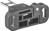
Access-Delay Frame-Mounted Safety Switches
|
Key Shown Actuating from the Side |
 |  |
Style A | Style B |
 | |
Style C |
Housing | Conduit | ||||||||||||||||||||||||||||||||||||||||||||||||||||||||||||||||||||||||||||||||||||||||||||||||||
|---|---|---|---|---|---|---|---|---|---|---|---|---|---|---|---|---|---|---|---|---|---|---|---|---|---|---|---|---|---|---|---|---|---|---|---|---|---|---|---|---|---|---|---|---|---|---|---|---|---|---|---|---|---|---|---|---|---|---|---|---|---|---|---|---|---|---|---|---|---|---|---|---|---|---|---|---|---|---|---|---|---|---|---|---|---|---|---|---|---|---|---|---|---|---|---|---|---|---|---|
Style | No. of Circuits Controlled | Switch Starting Position | Switch Action | No. of Terminals | Switch Designation | Switching Current @ Voltage | Max. Voltage | Input Voltage | Holding Force, lbf | Ht. | Wd. | Dp. | Trade Size | Thread Type | Enclosure Rating | Each | |||||||||||||||||||||||||||||||||||||||||||||||||||||||||||||||||||||||||||||||||||
Screw-Terminal Wire Connection with Positive-Force Normally Closed Contacts | |||||||||||||||||||||||||||||||||||||||||||||||||||||||||||||||||||||||||||||||||||||||||||||||||||
| A | 3 | 1 Off and 2 On | Maintained | 6 | 3PST-1NO/2NC | 5 amp @ 120V AC, 2 amp @ 24V DC | 500V AC 250V DC | 24V AC, 24V DC | 225 | 4.7" | 2.3" | 1.4" | 1/2 | NPT | IP67, NEMA 6 | 0000000 | 0000000 | ||||||||||||||||||||||||||||||||||||||||||||||||||||||||||||||||||||||||||||||||||
| A | 3 | 1 Off and 2 On | Maintained | 6 | 3PST-1NO/2NC | 5 amp @ 120V AC, 2 amp @ 24V DC | 500V AC 250V DC | 110V AC | 225 | 4.7" | 2.3" | 1.4" | 1/2 | NPT | IP67, NEMA 6 | 0000000 | 000000 | ||||||||||||||||||||||||||||||||||||||||||||||||||||||||||||||||||||||||||||||||||
| B | 3 | 1 Off and 2 On | Maintained | 14 | 3PST-1NO/2NC | 3 amp @ 120V AC, 2.5 amp @ 24V DC | 240V AC 250V DC | 24V DC | 225 | 3.7" | 3.5" | 1.4" | 1/2 | NPT | IP67 | 0000000 | 000000 | ||||||||||||||||||||||||||||||||||||||||||||||||||||||||||||||||||||||||||||||||||
Screw-Terminal Wire Connection with Positive-Force Normally Closed Contacts and Rotating Head | |||||||||||||||||||||||||||||||||||||||||||||||||||||||||||||||||||||||||||||||||||||||||||||||||||
| C | 4 | 2 Off and 2 On | Maintained | 8 | 4PST-2NO/2NC | 4 amp @ 120V AC, 4 amp @ 24V DC | 240V AC 24V DC | 24V AC, 24V DC | 225 | 7.6" | 1.2" | 1.6" | 1/2 | NPT | IP67 | 0000000 | 000000 | ||||||||||||||||||||||||||||||||||||||||||||||||||||||||||||||||||||||||||||||||||
