


About Moment Loads
More
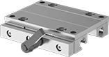
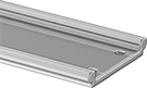
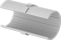
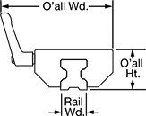
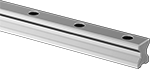
Locking Sleeve Bearing Carriages and Guide Rails
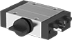
A handle on the side of the carriage locks the carriage in place. With fewer moving parts and no need for lubrication, sleeve bearing carriages perform better in dusty and wet environments than ball and roller bearing carriages. They're also better at handling impact and vibration.
Note: Load capacity is diminished when carriages are mounted upside down or on a vertical surface.
Aluminum Carriages and PTFE Plastic Bearings | |||||||||||||||||
|---|---|---|---|---|---|---|---|---|---|---|---|---|---|---|---|---|---|
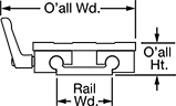
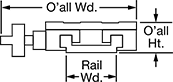
Mounting | Anodized Aluminum Guide Rails | ||||||||||||||||
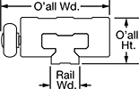
| For Rail Wd., mm | Static Load Cap., lbs. | O'all Wd., mm | O'all Ht., mm | Carriage Wd., mm | Carriage Lg., mm | Handle Dia., mm | Max. Temp., °F | No. of Holes | Hole Thread Size | Hole Thread Pitch, mm | Hole Dp., mm | Fasteners Included | Each | Rail Lengths, mm | Per mm | ||
| 15 | 900 | 63 | 24 | 47 | 68 | 20 | 190° | 4 | M5 | 0.8 | 16 | No | 000000 | 000000 | 0000000 | 00000 | |
| 20 | 1,650 | 80 | 30 | 63 | 81 | 28 | 190° | 4 | M6 | 1 | 19.8 | No | 000000 | 00000 | 0000000 | 000 | |
| 23 | 2,200 | 86 | 36 | 70 | 90 | 28 | 190° | 4 | M8 | 1.25 | 24.8 | No | 000000 | 00000 | 0000000 | 000 | |
| 30 | 3,100 | 110 | 42 | 90 | 103 | 28 | 190° | 4 | M10 | 1.5 | 27 | No | 000000 | 000000 | 0000000 | 000 | |
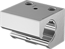
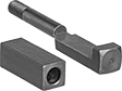
Self-Aligning Locking Sleeve Bearing Carriages and Guide Rails
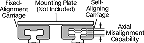
Create a self-aligning system that can be locked in place with these carriages and guide rails. The floating bearing in these self-aligning carriages compensates for misalignment, so carriages will still move in tandem even if the rails aren’t installed at the same exact height. A complete system includes a self-aligning carriage and rail on one side and a fixed-alignment carriage and rail on the other (all sold separately).
Note: Each carriage can only be used with its corresponding guide rail. Load capacity is diminished when carriages are mounted upside down or on a vertical surface.
Aluminum Carriages and PTFE Plastic Bearings | |||||||||||||||||
|---|---|---|---|---|---|---|---|---|---|---|---|---|---|---|---|---|---|
Mounting | Anodized Aluminum Guide Rails | ||||||||||||||||
| For Rail Wd., mm | Static Load Cap., lbs. | Axial Misalignment Capability, mm | O'all Wd., mm | O'all Ht., mm | Carriage Wd., mm | Carriage Lg., mm | Max. Temp., °F | No. of Holes | Hole Thread Size | Hole Thread Pitch, mm | Hole Dp., mm | Fasteners Included | Each | Rail Lengths, mm | Per mm | ||
| 15 | 900 | 1 | 63 | 24 | 47 | 68 | 190° | 4 | M5 | 0.8 | 16 | No | 0000000 | 0000000 | 0000000 | 00000 | |
| 20 | 1,650 | 1 | 80 | 30 | 63 | 81 | 190° | 4 | M6 | 1 | 19.8 | No | 0000000 | 000000 | 0000000 | 000 | |
| 23 | 2,200 | 1 | 86 | 36 | 70 | 90 | 190° | 4 | M8 | 1.25 | 24.8 | No | 0000000 | 000000 | 0000000 | 000 | |
| 30 | 3,100 | 1 | 110 | 42 | 90 | 103 | 190° | 4 | M10 | 1.5 | 27 | No | 0000000 | 000000 | 0000000 | 000 | |
Aluminum Carriages and PTFE Plastic Bearings | ||||||||||||||||
|---|---|---|---|---|---|---|---|---|---|---|---|---|---|---|---|---|
Mounting | Anodized Aluminum Guide Rails | |||||||||||||||
| For Rail Wd., mm | Static Load Cap., lbs. | O'all Wd., mm | O'all Ht., mm | Carriage Wd., mm | Carriage Lg., mm | Max. Temp., °F | No. of Holes | Hole Thread Size | Hole Thread Pitch, mm | Hole Dp., mm | Fasteners Included | Each | Rail Lengths, mm | Per mm | ||
| 15 | 900 | 63 | 24 | 47 | 68 | 190° | 4 | M5 | 0.8 | 16 | No | 000000 | 000000 | 0000000 | 00000 | |
| 20 | 1,650 | 80 | 30 | 63 | 81 | 190° | 4 | M6 | 1 | 19.8 | No | 000000 | 00000 | 0000000 | 000 | |
| 23 | 2,200 | 86 | 36 | 70 | 90 | 190° | 4 | M8 | 1.25 | 24.8 | No | 000000 | 00000 | 0000000 | 000 | |
| 30 | 3,100 | 110 | 42 | 90 | 103 | 190° | 4 | M10 | 1.5 | 27 | No | 000000 | 000000 | 0000000 | 000 | |
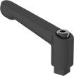
Locking Extra-Wide Sleeve Bearing Carriages and Guide Rails

A handle on the side of the carriage locks the carriage in place. Carriages have a wide base for stabilizing moment (twisting) and off-center loads better than standard sleeve bearing carriages. Use them in areas where multiple carriages or rails won't fit. The sleeve bearings allow them to outperform ball bearings in wet, dirty, and high-vibration environments. Mount in any orientation without affecting load capacity.
Aluminum carriages conduct and dissipate the heat produced by friction, protecting your machinery. They are more corrosion resistant than zinc carriages.
Zinc carriages are mildly corrosion resistant.
Aluminum Carriages and PTFE Plastic Bearings | |||||||||||||||||||
|---|---|---|---|---|---|---|---|---|---|---|---|---|---|---|---|---|---|---|---|
Mounting | Anodized Aluminum Guide Rails | ||||||||||||||||||
| For Rail Wd., mm | Static Load Cap., lbs. | O'all Wd., mm | O'all Ht., mm | Carriage Wd., mm | Carriage Lg., mm | Handle Lg., mm | Max. Temp., °F | No. of Holes | Hole Thread Size | Hole Thread Pitch, mm | Hole Dp., mm | Fasteners Included | Rail Shape | Rail Shape | Each | Rail Lengths, mm | Per mm | ||
Round | |||||||||||||||||||
| 40 | 1,050 | 101 | 24 | 73 | 100 | 40 | 190° | 4 | M6 | 1 | 19 | No | Straight | Straight | 00000000 | 0000000 | 0000000 | 00000 | |
| 40 | 1,050 | 101 | 24 | 73 | 150 | 40 | 190° | 4 | M6 | 1 | 19 | No | Straight | Straight | 00000000 | 000000 | 0000000 | 000 | |
Zinc Carriages and PTFE Plastic Bearings | |||||||||||||||||||
|---|---|---|---|---|---|---|---|---|---|---|---|---|---|---|---|---|---|---|---|
Mounting | Anodized Aluminum Guide Rails | ||||||||||||||||||
| For Rail Wd., mm | Static Load Cap., lbs. | O'all Wd., mm | O'all Ht., mm | Carriage Wd., mm | Carriage Lg., mm | Handle Lg., mm | Max. Temp., °F | No. of Holes | Hole Thread Size | Hole Thread Pitch, mm | Hole Dp., mm | Fasteners Included | Rail Shape | Rail Shape | Each | Rail Lengths, mm | Per mm | ||
Square | |||||||||||||||||||
| 27 | 370 | 82 | 18 | 54 | 60 | 28 | 190° | 4 | M4 | 0.7 | 15 | No | __ | __ | 00000000 | 0000000 | 0000000 | 00000 | |
| 27 | 370 | 82 | 18 | 54 | 80 | 28 | 190° | 4 | M4 | 0.7 | 15 | No | __ | __ | 00000000 | 00000 | 0000000 | 000 | |
Round | |||||||||||||||||||
| 40 | 1,050 | 101 | 24 | 73 | 100 | 40 | 190° | 4 | M6 | 1 | 19 | No | Straight | Straight | 00000000 | 000000 | 0000000 | 000 | |
| 40 | 1,050 | 101 | 24 | 73 | 150 | 40 | 190° | 4 | M6 | 1 | 19 | No | Straight | Straight | 00000000 | 000000 | 0000000 | 000 | |
| 40 | 1,050 | 101 | 24 | 73 | 200 | 40 | 190° | 4 | M6 | 1 | 19 | No | Straight | Straight | 00000000 | 000000 | 0000000 | 000 | |
| 54 | 1,880 | 132 | 35 | 104 | 150 | 40 | 190° | 4 | M8 | 1.25 | 30 | No | __ | __ | 00000000 | 000000 | 0000000 | 000 | |
| 54 | 1,880 | 132 | 35 | 104 | 200 | 40 | 190° | 4 | M8 | 1.25 | 30 | No | __ | __ | 00000000 | 000000 | 0000000 | 000 | |
| 74 | 1,050 | 147 | 24 | 107 | 100 | 40 | 190° | 4 | M6 | 1 | 19 | No | __ | __ | 00000000 | 000000 | 0000000 | 000 | |
| 74 | 2,850 | 174 | 44 | 134 | 150 | 40 | 190° | 4 | M8 | 1.25 | 38 | No | __ | __ | 00000000 | 000000 | 0000000 | 000 | |
| 74 | 2,870 | 174 | 44 | 134 | 250 | 40 | 190° | 4 | M8 | 1.25 | 38 | No | __ | __ | 00000000 | 000000 | 0000000 | 000 | |
Locking Sleeve Bearing Carriages and Guide Rails for Curves
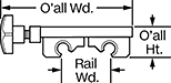


A handle locks these carriages in place on curved paths, loops, and circuits in assembly stations and other repetitive processes. Because these carriages and rails have a wide base, they stabilize twisting and off-center loads better than standard carriages and rails. They’re useful in areas that won’t fit multiple rails or carriages. The carriages have sleeve bearings that swivel, so they move around curves without jamming. Their sleeve bearings also work better than ball bearings in wet, dirty, and high-vibration environments. Mount them in any orientation.
Aluminum Carriages and PTFE Plastic Bearings | 90° Angle Anodized Aluminum Guide Rails | U-Shape Anodized Aluminum Guide Rails | Round Anodized Aluminum Guide Rails | Straight Anodized Aluminum Guide Rails | |||||||||||||||
|---|---|---|---|---|---|---|---|---|---|---|---|---|---|---|---|---|---|---|---|
| For Rail Bend Radius, mm | Static Load Cap., lbs. | O'all Wd., mm | O'all Ht., mm | Carriage Wd., mm | Carriage Lg., mm | Each | Rail Length, mm | Each | Rail Length, mm | Each | Rail Length, mm | Each | Rail Lengths, mm | Per mm | |||||
For 40 mm Rail Width | |||||||||||||||||||
| 300 | 220 | 114 | 28 | 80 | 102 | 0000000 | 0000000 | 671 | 0000000 | 0000000 | 1,143 | 0000000 | 0000000 | 1,883 | 0000000 | 0000000 | 0000000 | 00000 | |
| 500 | 220 | 114 | 28 | 80 | 102 | 0000000 | 000000 | 985 | 0000000 | 000000 | 1,771 | 0000000 | 000000 | 3,140 | 0000000 | 000000 | 0000000 | 000 | |
Locking High-Load Track Roller Carriages and Guide Rails
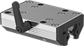
A handle on the side of the carriage locks the carriage in place. Made with needle-roller bearings, these track roller carriages have higher load capacities than other track roller carriages. Carriages can be adjusted for a snug or loose fit on the rail (also known as preload). Rollers are permanently lubricated to save maintenance time and effort.
Aluminum Carriages with Adjustable Steel Rollers | Anodized Aluminum Guide Rails | Replacement Clamp Jaw Kits | Replacement Locking Handles | ||||||||||||||
|---|---|---|---|---|---|---|---|---|---|---|---|---|---|---|---|---|---|
| For Rail Wd., mm | Dynamic Load Cap., lbs. | O'all Wd., mm | O'all Ht., mm | Carriage Wd., mm | Carriage Lg., mm | Handle Lg., mm | Max. Temp., °F | Max. Clamping Force, lbs. | Each | Rail Lengths, mm | Per mm | Each | Each | ||||
| 15.5 | 940 | 80 | 24 | 47 | 88 | 45 | 175° | 40 | 0000000 | 0000000 | 0000000 | 00000 | 0000000 | 0000000 | 0000000 | 000000 | |
| 21 | 1,200 | 63 | 30 | 63 | 102 | 45 | 175° | 55 | 0000000 | 000000 | 0000000 | 000 | 0000000 | 000000 | 0000000 | 00000 | |
| 23 | 2,000 | 103 | 36 | 70 | 108 | 45 | 175° | 55 | 0000000 | 000000 | 0000000 | 000 | 0000000 | 000000 | 0000000 | 00000 | |
| 32 | 2,800 | 142 | 48 | 100 | 145 | 78 | 175° | 75 | 0000000 | 000000 | 0000000 | 000 | 0000000 | 000000 | 0000000 | 00000 | |
| 45 | 4,700 | 120 | 60 | 120 | 175 | 78 | 175° | 165 | 0000000 | 000000 | 0000000 | 000 | 0000000 | 000000 | 000000 | 00 | |