


Electronic Magnetic Pole Detectors
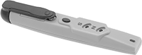
Point this detector at your magnet and press the button. Red and green lights indicate north or south poles.
| Lg. | Wd. | Batteries Included | Each | |
| 5 1/2" | 1" | Yes | 00000000 | 000000 |
Digital Magnetic Field Meters
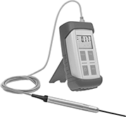
Measure magnetic fields to determine electromagnetic interference and detect flaws in welded metal. Product regulations restrict sales to the listed jurisdictions/areas.
| Scale | Measuring Range (Increments) | Accuracy | Frequency Bandwidth | Batteries Included | Includes | Cannot Be Sold To | Each | |
| Ampere/Meters, Gauss, Tesla | 0-100 Gauss (.01 Gauss) 0-1 Kilogauss (.1 Gauss) 0-10 Kilogauss (1 Gauss) 0-45 Kilogauss (10 Gauss) | 2% | 0-5 kHz | Yes | AC Adapter, Detachable Probe | CA | 0000000 | 000000000 |
Digital Electromagnetic Field Meters
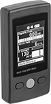
Measure the strength of magnetic fields, electric fields, and radio frequencies at the same time. To detect emissions, just point these meters at the electrical equipment you want to test, such as a cable. When they detect high levels that could damage sensitive equipment, an alert appears in red and an audible alarm sounds. Their color LCD display shows readings, bar graphs, and trending graphs.
These meters store up to 20 radio frequency readings. Send readings to your PC using a USB cable (not included).
| Scale | Measures | Measuring Range (Increments) | Accuracy | Frequency Bandwith | Ht. | Wd. | Dp. | Batteries Included | Each | |
| Gauss, Tesla | Magnetic Field Strength Electric Field Strength Radio Frequency Strength Magnetic Field Direction (3-Axis) | 0.02-2 Gauss (0.01 Gauss) 50-2,000 V/m (1 V/m) 0.03-14.46 V/m (0.02 V/m) | ±15% ±7% ±2 dB | 0.05-0.06 kHz 0.05-0.06 kHz 50,000-3,500,000 kHz | 4 1/2" | 2 1/2" | 1" | Yes | 0000000 | 0000000 |
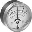
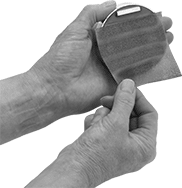
Calibrated-Dial Magnetic Field Indicators with Certificate of Calibration
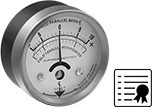
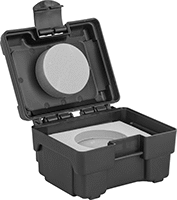
These indicators come with a calibration certificate traceable to NIST that states they've passed a test for accuracy. All are calibrated at 72° F. In addition to measuring the strength of a magnetic field in gauss, they also measure the direction of a magnetic field in positive/negative. To take a measurement, place the lower edge of the indicator near or against your tools and parts.
Calibrated-Dial Magnetic Field Indicators
Calibrated at 72° F. In addition to measuring the strength of a magnetic field in gauss, these indicators also measure the direction of a magnetic field in positive/negative. To take a measurement, place the lower edge of the indicator near or against your tools and parts.
Indicators | |||||||
|---|---|---|---|---|---|---|---|
Dial | Protective Cases | ||||||
| Measuring Range | Dia. | Face Color | Housing Material | Each | Each | ||
| 5-0-5 gauss | 2 1/2" | White | Aluminum | 0000000 | 0000000 | 0000000 | 000000 |
| 10-0-10 gauss | 2 1/2" | White | Aluminum | 0000000 | 000000 | 0000000 | 00000 |
| 20-0-20 gauss | 2 1/2" | White | Aluminum | 0000000 | 000000 | 0000000 | 00000 |
| 50-0-50 gauss | 2 1/2" | White | Aluminum | 0000000 | 000000 | 0000000 | 00000 |
Dial Magnetic Field Indicators
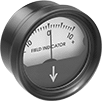
Place the lower edge of these dial indicators near or against your tools and parts to measure the strength of a magnetic field in gauss.
Dial | |||||
|---|---|---|---|---|---|
| Measuring Range | Dia. | Face Color | Housing Material | Each | |
| 10-0-10 gauss | 2" | White | Plastic | 0000000 | 0000000 |
Magnetic Field Detectors
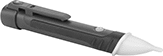
Troubleshoot solenoid valves, check relays, and test permanent magnets by detecting if a magnetic field is present. Hold these detectors near a surface and they'll light up blue if they sense a magnetic field. They don't measure the strength or direction of the magnetic field.
| Detects | Lg. | Wd. | Batteries Included | Features | Each | |
| Magnetic Fields | 6 1/4" | 1" | Yes | Flashlight, Low Battery Indicator | 0000000 | 000000 |
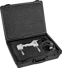
Plug-In Magnetic Particle Flaw-Detection Kits
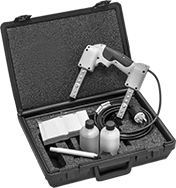
Find faulty seams, welding defects, and other surface-level flaws in ferrous materials. These kits come with everything you need to start inspecting parts. Apply the powder to the surface you want to inspect. Then plug in the yoke and it creates a magnetic field that draws the powder to the imperfection, making it easy to spot. Built for rugged environments, the yoke has a sealed design that stands up to chemicals and other harsh conditions. It’s also half the weight of a standard yoke and fits comfortably in your hand, so there’s less fatigue if you use it for extended periods of time.
| For Use On | Includes | Plug Type | Voltage | Specifications Met | Each | |
| Cast Iron, Stainless Steel, Steel | One 1-lb. Bottle of Gray Powder, One 1-lb. Bottle of Red Powder | Three Prong | 120V AC | ASTM E1444, MIL-STD-2132, MIL-STD-271 | 000000 | 0000000 |
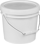
Particles for Magnetic-Particle Flaw Detection
Reveal imperfections both at and slightly below the surface of your metal part, unlike other flaw detection methods. Use these particles with a magnetic yoke to check for faulty seams, welding defects, and fatigue cracks to make sure metal parts will be safe under high stress. The yoke creates a magnetic field that draws the particles towards flaws, making them easy to spot. To prevent issues with other inspections down the line, make sure to fully demagnetize your part to remove all the particles.
Powder particles withstand higher temperatures than spray particles and are quick to use. They don’t need to dry, which means you can start testing immediately. Shake them out from a bottle or use a powder blower to apply them to your part. You can blow excess particles off even if your part is still magnetized. They come in different colors, so choose what will contrast best with your metal surface.
When testing round or hard-to-reach material, it’s easier to apply an even layer of spray particles than powder. They’re smaller than powder particles, so they’re good for detecting finer surface flaws and imperfections. Particles with a 360° sprayer won’t sputter or spatter even when the aerosol can is upside down, so you can coat parts evenly without straining your wrist. Water-based spray particles are easier to clean up than oil-based spray particles. Black spray particles are often used with white contrast paint to make flaws more visible.
Ultraviolet spray particles require a UV light, but stand out more than natural light particles, so you spend less time examining each part. For the best contrast, use these particles in dim lighting.
Container | Application Temp. Range | ||||||||||
|---|---|---|---|---|---|---|---|---|---|---|---|
| For Use On | Visibility | Color | Net Weight | Type | Particle Size, microns | Min., °F | Max., °F | Features | Specifications Met | Each | |
Powder | |||||||||||
| Cobalt, Iron, Nickel, Stainless Steel, Steel | Natural Light | Gray | 10 lbs. | Pail | 80 | Not Rated | 750° | __ | ASTM E1444, MIL-STD-2132, MIL-STD-271, NAVSEA 250-1500-1, NAVSEA T9074-AS-GIB-010/271 | 00000000 | 0000000 |
| Cobalt, Iron, Nickel, Stainless Steel, Steel | Natural Light | Red | 10 lbs. | Pail | 80 | Not Rated | 600° | __ | ASTM E1444, ISO 9934, MIL-STD-2132, MIL-STD-271, NAVSEA 250-1500-1, NAVSEA T9074-AS-GIB-010/271 | 00000000 | 000000 |
| Cobalt, Iron, Nickel, Stainless Steel, Steel | Natural Light | Yellow | 10 lbs. | Pail | 80 | Not Rated | 500° | __ | ASTM E1444, ISO 9934, MIL-STD-2132, MIL-STD-271, NAVSEA 250-1500-1, NAVSEA T9074-AS-GIB-010/271 | 00000000 | 000000 |
Oil-Based Spray | |||||||||||
| Cobalt, Iron, Nickel, Stainless Steel, Steel | Natural Light | Black | 10.5 oz. | Aerosol Can | __ | 45° | 120° | 360° Sprayer | ASTM E1444, ISO 9934, MIL-STD-2132, NAVSEA 250-1500-1, NAVSEA T9074-AS-GIB-010/271 | 00000000 | 00000 |
| Cobalt, Iron, Nickel, Stainless Steel, Steel | Ultraviolet | Fluorescent Light Green | 10.5 oz. | Aerosol Can | 6 | 55° | 120° | __ | ASTM E1444, ISO 9934, MIL-STD-2132, MIL-STD-271, NAVSEA 250-1500-1, NAVSEA T9074-AS-GIB-010/271 | 0000000 | 00000 |
Water-Based Spray | |||||||||||
| Cobalt, Iron, Nickel, Stainless Steel, Steel | Natural Light | Black | 12.2 oz. | Aerosol Can | __ | 25° | 120° | __ | ISO 9934, MIL-STD-2132, NAVSEA 250-1500-1, NAVSEA T9074-AS-GIB-010/271 | 00000000 | 00000 |
Battery-Powered Magnetic Particle Flaw-Detection Kits
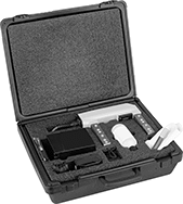
Check for defects slightly beneath the surface of ferrous materials that you wouldn’t otherwise see. The yoke in these kits is powered by a battery, so it uses direct current to create a strong magnetic field that reaches just below the surface of your part. When you apply the powder, the powder will move towards any flaws, helping you identify tears, cracks, and other imperfections.
Ideal for fieldwork, these kits come with everything you need for on-the-go inspections. The yoke lasts up to eight hours on a single battery charge. Built for rugged environments, it has a sealed design that stands up to chemicals and other harsh conditions.
| For Use On | Includes | Battery Voltage | Batteries Included | Battery Charger Included | Specifications Met | Each | |
| Cobalt, Iron, Nickel, Stainless Steel, Steel | One 1-lb. Bottle of Gray Powder | 6V DC | Yes | Yes | ASTM E1444 | 0000000 | 000000000 |
Plug-In Yokes for Magnetic-Particle Flaw Detection
Find welding defects and other flaws in magnetic materials. These yokes create a magnetic field that draws magnetic powder (not included) to imperfections, making them easy to spot. All operate on AC power, which creates a small magnetic field ideal for detecting flaws along the surface of materials. Powered by standard electrical outlets, these yokes have a reliable and consistent power source.
6-lb. yokes are lightweight and fit comfortably in your hand to reduce fatigue over extended use. Attach an LED light to your yoke to brightly illuminate inspection areas. They’re powered by the yoke’s magnetic field, so they don’t require batteries.
Yokes with an AC/DC switch can also operate on DC power. DC power generates a deeper magnetic field than AC power to find defects underneath surfaces, such as internal tears and cracks.
Calibrate your yoke before each use with a test weight to ensure accurate test results.
Yokes | Test Weights | LED Light Attachments | Replacement Cords | |||||||||||||
|---|---|---|---|---|---|---|---|---|---|---|---|---|---|---|---|---|
| Voltage | Features | For Use On | Power Source | Cord Lg. | Ht. | Lg. | Weight, lbs. | Specifications Met | Each | Each | Each | Each | ||||
| 120V AC | __ | Cobalt, Iron, Nickel, Stainless Steel, Steel | Electric | 12 ft. | 7 1/2" | 12" | 6 | ASTM E1444 | 0000000 | 0000000 | 0000000 | 0000000 | 0000000 | 0000000 | 0000000 | 0000000 |
| 120V AC | AC/DC Switch | Cobalt, Iron, Nickel, Stainless Steel, Steel | Electric | 12 ft. | 7 1/2" | 12" | 8 | ASTM E1444 | 0000000 | 00000000 | 0000000 | 000000 | 000000 | 00 | 000000 | 00 |
Contrast Paint for Magnetic-Particle Flaw Detection
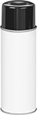
Create a high-contrast background for magnetic particles to make flaws easier to spot during inspections. This opaque white paint reduces glare, so you can see where particles are clustered around imperfections. No need for brushes—it comes in an aerosol can that’s easy to use during field testing and spot inspections. Even when the can is upside down, the 360° sprayer won’t sputter or spatter, so you can coat parts evenly without straining your wrist. To speed up inspections, this paint dries quickly, leaving a clean coat that won’t bubble or flake. It works with both wet and dry magnetic particles.
Container | |||||||||
|---|---|---|---|---|---|---|---|---|---|
| Net Weight, oz. | Type | Composition | O'all Dry Time | Application Temperature Range, °F | For Use On | Color | Features | Each | |
Spray | |||||||||
| 12 | Aerosol Can | Solvent Based | 1 min. | 45° to 120° | Cast Iron, Cobalt, Iron, Nickel, Stainless Steel, Steel | White | 360° Sprayer | 0000000 | 000000 |
Motion-Measuring Modules for Development Boards
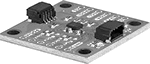
Measure your device's acceleration, rotation, or orientation. These modules gather data over time and track movement, which can help improve performance, debug issues, and calibrate your components. Solder them onto a development board. To connect them to your device, solder on a wire or header. For a solderless connection, use a Qwiic cord (not included).
An accelerometer measures the rate at which your device is speeding up or slowing down. A gyroscope measures how fast your device is rotating. A magnetometer measures your device's orientation.
Output Data | |||||||||||
|---|---|---|---|---|---|---|---|---|---|---|---|
| Acceleration | Velocity | Magnetic Field | Resolution, bit | Frequency, kHz | Input Voltage | I2C Address | No. of Qwiic Connections | Lg. | Wd. | Each | |
I2C Communication Protocol—Qwiic Connection | |||||||||||
Modules with Magnetometer | |||||||||||
| __ | __ | 0-8 gauss | 18 | 1 | 2.8-3.6V DC | 0x30 | 1 | 3/4" | 5/16" | 0000000 | 000000 |
Modules with Accelerometer, Gyroscope, and Magnetometer | |||||||||||
| 2 g 4 g 8 g 16 g | 125°/s 250°/s 500°/s 1,000°/s 2,000°/s 4,000°/s | 0-8 gauss | 18 | 1 | 1.71-3.6V DC | 0x6A 0x6B 0x30 | 2 | 1" | 1" | 0000000 | 00000 |