


Filter by
Switch Starting Position
Wire Connection

Switch Designation
Certification
DFARS Specialty Metals
U.S.–Mexico–Canada Agreement (USMCA) Qualifying
Export Control Classification Number (ECCN)
Electrical Connection
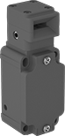
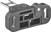
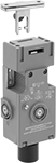
Frame-Mounted Safety Switches
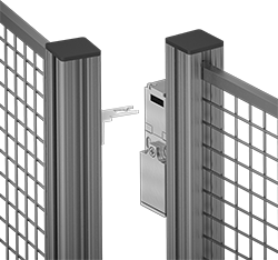 |
Key Shown Actuating from the Side |
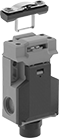 | 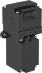 | |||
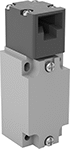
Style A | Style B | Style C | Style D | Style E |
 |  | 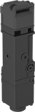 |  | |
Style F | Style G | Style H | Style J |
Housing | Conduit | ||||||||||||||||||||||||||||||||||||||||||||||||||||||||||||||||||||||||||||||||||||||||||||||||||
|---|---|---|---|---|---|---|---|---|---|---|---|---|---|---|---|---|---|---|---|---|---|---|---|---|---|---|---|---|---|---|---|---|---|---|---|---|---|---|---|---|---|---|---|---|---|---|---|---|---|---|---|---|---|---|---|---|---|---|---|---|---|---|---|---|---|---|---|---|---|---|---|---|---|---|---|---|---|---|---|---|---|---|---|---|---|---|---|---|---|---|---|---|---|---|---|---|---|---|---|
Style | No. of Circuits Controlled | Switch Starting Position | Switch Action | No. of Terminals | Switch Designation | Switching Current @ Voltage | Max. Voltage | Ht. | Wd. | Dp. | Trade Size | Thread Size | Thread Type | Key Included | Enclosure Rating | Each | |||||||||||||||||||||||||||||||||||||||||||||||||||||||||||||||||||||||||||||||||||
Wire Lead Connection with Positive-Force Normally Closed Contacts | |||||||||||||||||||||||||||||||||||||||||||||||||||||||||||||||||||||||||||||||||||||||||||||||||||
| A | 2 | 1 Off and 1 On | Maintained | 2 | DPST-1NO/1NC | 8 amp @ 120V AC, 4 amp @ 24V DC | 250V AC 24V DC | 3.3" | 1.2" | 1.2" | — | M16 | Metric | Yes | IP67 | 65665K25 | 0000000 | ||||||||||||||||||||||||||||||||||||||||||||||||||||||||||||||||||||||||||||||||||
Screw-Terminal Wire Connection with Positive-Force Normally Closed Contacts | |||||||||||||||||||||||||||||||||||||||||||||||||||||||||||||||||||||||||||||||||||||||||||||||||||
| B | 2 | 1 Off and 1 On | Maintained | 4 | DPST-1NO/1NC | 5 amp @ 120V AC, 2 amp @ 24V DC | 500V AC 250V DC | 3" | 1" | 1.1" | 1/2 | — | NPT | Yes | IP67, NEMA 6 | 65665K32 | 000000 | ||||||||||||||||||||||||||||||||||||||||||||||||||||||||||||||||||||||||||||||||||
| C | 2 | 1 Off and 1 On | Maintained | 4 | DPST-1NO/1NC | 10 amp @ 120V AC, 2 amp @ 24V DC | 250V AC 24V DC | 3.6" | 2.1" | 1.3" | 1/2 | — | NPT | Yes | IP65, NEMA 4 | 65665K13 | 000000 | ||||||||||||||||||||||||||||||||||||||||||||||||||||||||||||||||||||||||||||||||||
| C | 3 | 1 Off and 2 On | Maintained | 3 | 3PST-1NO/2NC | 8 amp @ 120V AC, 4 amp @ 24V DC | 600V AC 250V DC | 3.5" | 2.1" | 1.2" | 1/2 | — | NPT | Yes | IP67 | 65665K15 | 000000 | ||||||||||||||||||||||||||||||||||||||||||||||||||||||||||||||||||||||||||||||||||
| C | 3 | 1 Off and 2 On | Maintained | 6 | 3PST-1NO/2NC | 4 amp @ 230V AC, 4 amp @ 24V DC | 500V AC 24V DC | 3.5" | 2" | 1.2" | — | M16 | Metric | Yes | IP67 | 65665K18 | 000000 | ||||||||||||||||||||||||||||||||||||||||||||||||||||||||||||||||||||||||||||||||||
| D | 3 | 1 Off and 2 On | Maintained | 6 | 3PST-1NO/2NC | 6 amp @ 120V AC, 0.27 amp @ 24V DC | 240V AC 250V DC | 3.8" | 1.2" | 1.2" | 1/2 | — | NPT | Yes | IP67 | 65665K16 | 00000 | ||||||||||||||||||||||||||||||||||||||||||||||||||||||||||||||||||||||||||||||||||
| E | 2 | 1 Off and 1 On | Maintained | 4 | DPST-1NO/1NC | 8 amp @ 230V AC, 5 amp @ 24V DC | 400V AC 24V DC | 4.2" | 2" | 1.6" | — | M20 | Metric | No | IP67 | 65665K43 | 00000 | ||||||||||||||||||||||||||||||||||||||||||||||||||||||||||||||||||||||||||||||||||
| E | 2 | 2 On | Maintained | 4 | DPST-NC | 8 amp @ 230V AC, 5 amp @ 24V DC | 400V AC 24V DC | 4.2" | 2" | 1.6" | — | M20 | Metric | No | IP67 | 65665K22 | 00000 | ||||||||||||||||||||||||||||||||||||||||||||||||||||||||||||||||||||||||||||||||||
| F | 2 | 1 Off and 1 On | Maintained | 4 | DPST-1NO/1NC | 2 amp @ 400V AC | 400V AC | 4.4" | 1.6" | 1.6" | — | M20 | Metric | No | IP67 | 65665K112 | 000000 | ||||||||||||||||||||||||||||||||||||||||||||||||||||||||||||||||||||||||||||||||||
| F | 2 | 1 Off and 1 On | Maintained | 4 | DPST-1NO/1NC | 2 amp @ 400V AC | 400V AC | 4.4" | 1.6" | 1.6" | 1/2 | — | BSPP | No | IP67 | 65665K111 | 000000 | ||||||||||||||||||||||||||||||||||||||||||||||||||||||||||||||||||||||||||||||||||
| F | 2 | 1 Off and 1 On | Maintained | 4 | DPST-1NO/1NC | 2 amp @ 400V AC | 400V AC | 4.4" | 1.6" | 1.6" | 1/2 | — | NPT | No | IP67 | 65665K105 | 000000 | ||||||||||||||||||||||||||||||||||||||||||||||||||||||||||||||||||||||||||||||||||
| F | 2 | 2 On | Maintained | 4 | DPST-NC | 2 amp @ 400V AC | 400V AC | 4.4" | 1.6" | 1.6" | — | M20 | Metric | No | IP67 | 65665K113 | 00000 | ||||||||||||||||||||||||||||||||||||||||||||||||||||||||||||||||||||||||||||||||||
| F | 2 | 2 On | Maintained | 4 | DPST-NC | 2 amp @ 400V AC | 400V AC | 4.4" | 1.6" | 1.6" | 1/2 | — | BSPP | No | IP67 | 65665K108 | 00000 | ||||||||||||||||||||||||||||||||||||||||||||||||||||||||||||||||||||||||||||||||||
| F | 2 | 2 On | Maintained | 4 | DPST-NC | 2 amp @ 400V AC | 400V AC | 4.4" | 1.6" | 1.6" | 1/2 | — | NPT | No | IP67 | 65665K109 | 000000 | ||||||||||||||||||||||||||||||||||||||||||||||||||||||||||||||||||||||||||||||||||
Screw-Terminal Wire Connection with Positive-Force Normally Closed Contacts and Rotating Head | |||||||||||||||||||||||||||||||||||||||||||||||||||||||||||||||||||||||||||||||||||||||||||||||||||
| C | 3 | 1 Off and 2 On | Maintained | 6 | 3PST-1NO/2NC | 5 amp @ 120V AC, 5 amp @ 24V DC | 400V AC 400V DC | 3.5" | 2" | 1.3" | 1/2 | — | NPT | Yes | IP65 | 65665K51 | 000000 | ||||||||||||||||||||||||||||||||||||||||||||||||||||||||||||||||||||||||||||||||||
| D | 3 | 1 Off and 2 On | Maintained | 6 | 3PST-1NO/2NC | 10 amp @ 120V AC, 2.5 amp @ 125V DC | 240V AC 250V DC | 3.8" | 1.2" | 1.2" | — | M20 | Metric | No | IP67 | 65665K29 | 00000 | ||||||||||||||||||||||||||||||||||||||||||||||||||||||||||||||||||||||||||||||||||
| G | 3 | 1 Off and 2 On | Maintained | 6 | 3PST-1NO/2NC | 10 amp @ 230V AC, 4 amp @ 24V DC | 250V AC 24V DC | 4.3" | 1.6" | 1.4" | — | M20 | Metric | No | IP67 | 65665K19 | 000000 | ||||||||||||||||||||||||||||||||||||||||||||||||||||||||||||||||||||||||||||||||||
Screw-Terminal Wire Connection with Rotating Head | |||||||||||||||||||||||||||||||||||||||||||||||||||||||||||||||||||||||||||||||||||||||||||||||||||
| H | 4 | 2 Off and 2 On | Maintained | 8 | 4PST-2NO/2NC | 2.5 amp @ 120V AC, 1 amp @ 125V DC | 120V AC 125V DC | 7.1" | 1.5" | 1.5" | 1/2 | — | NPT | No | IP67 | 65665K31 | 000000 | ||||||||||||||||||||||||||||||||||||||||||||||||||||||||||||||||||||||||||||||||||
Screw-Terminal Wire Connection with Rear Release Button, Portable Key, and LED Status Indicator | |||||||||||||||||||||||||||||||||||||||||||||||||||||||||||||||||||||||||||||||||||||||||||||||||||
| J | 6 | 2 Off and 4 On | Maintained | 12 | 6PST-2NO/4NC | 3 amp @ 240V AC, 2.5 amp @ 250V DC | 240V AC 250V DC | 5.2" | 4.6" | 2.2" | — | M20 | Metric | Yes | IP67 | 65665K101 | 000000 | ||||||||||||||||||||||||||||||||||||||||||||||||||||||||||||||||||||||||||||||||||
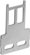 |  |  |
Straight | 90° Angle | Flexible |
O'all, mm | |||||||||||||||||||||||||||||||||||||||||||||||||||||||||||||||||||||||||||||||||||||||||||||||||||
|---|---|---|---|---|---|---|---|---|---|---|---|---|---|---|---|---|---|---|---|---|---|---|---|---|---|---|---|---|---|---|---|---|---|---|---|---|---|---|---|---|---|---|---|---|---|---|---|---|---|---|---|---|---|---|---|---|---|---|---|---|---|---|---|---|---|---|---|---|---|---|---|---|---|---|---|---|---|---|---|---|---|---|---|---|---|---|---|---|---|---|---|---|---|---|---|---|---|---|---|
For Style | Angle Range | Adjustment Direction | Lg. | Wd. | Mounting Fasteners Included | Each | |||||||||||||||||||||||||||||||||||||||||||||||||||||||||||||||||||||||||||||||||||||||||||||
Straight | |||||||||||||||||||||||||||||||||||||||||||||||||||||||||||||||||||||||||||||||||||||||||||||||||||
| E | — | — | 80 | 32 | No | 65665K27 | 000000 | ||||||||||||||||||||||||||||||||||||||||||||||||||||||||||||||||||||||||||||||||||||||||||||
| F | — | — | 53.7 | 52.4 | No | 65665K107 | 00000 | ||||||||||||||||||||||||||||||||||||||||||||||||||||||||||||||||||||||||||||||||||||||||||||
| G | — | — | 86 | 32 | No | 65665K24 | 00000 | ||||||||||||||||||||||||||||||||||||||||||||||||||||||||||||||||||||||||||||||||||||||||||||
| H | — | — | 48.5 | 35 | No | 65665K41 | 00000 | ||||||||||||||||||||||||||||||||||||||||||||||||||||||||||||||||||||||||||||||||||||||||||||
| J | — | — | 61.5 | 40 | No | 65665K102 | 00000 | ||||||||||||||||||||||||||||||||||||||||||||||||||||||||||||||||||||||||||||||||||||||||||||
90° Angle | |||||||||||||||||||||||||||||||||||||||||||||||||||||||||||||||||||||||||||||||||||||||||||||||||||
| E | — | — | 65.5 | 32 | No | 65665K28 | 00000 | ||||||||||||||||||||||||||||||||||||||||||||||||||||||||||||||||||||||||||||||||||||||||||||
| J | — | — | 45 | 40 | No | 65665K103 | 00000 | ||||||||||||||||||||||||||||||||||||||||||||||||||||||||||||||||||||||||||||||||||||||||||||
Flexible | |||||||||||||||||||||||||||||||||||||||||||||||||||||||||||||||||||||||||||||||||||||||||||||||||||
| D | 0° to 15° | Up/Down/Left/Right | 48.9 | 55 | No | 65665K167 | 00000 | ||||||||||||||||||||||||||||||||||||||||||||||||||||||||||||||||||||||||||||||||||||||||||||
| F | 0° to 18° | Left/Right | 80.7 | 40 | No | 65665K106 | 00000 | ||||||||||||||||||||||||||||||||||||||||||||||||||||||||||||||||||||||||||||||||||||||||||||
| G | 0° to 15° | Up/Down/Left/Right | 105 | 40 | No | 65665K45 | 000000 | ||||||||||||||||||||||||||||||||||||||||||||||||||||||||||||||||||||||||||||||||||||||||||||
| H | 0° to 15° | Up/Down/Left/Right | 50.4 | 55 | No | 65665K42 | 00000 | ||||||||||||||||||||||||||||||||||||||||||||||||||||||||||||||||||||||||||||||||||||||||||||
| J | 0° to 18° | Left/Right | 70 | 40 | No | 65665K104 | 00000 | ||||||||||||||||||||||||||||||||||||||||||||||||||||||||||||||||||||||||||||||||||||||||||||
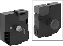
Access-Delay Frame-Mounted Safety Switches
|
Key Shown Actuating from the Side |
 | 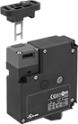 |
Style A | Style B |
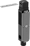 | |
Style C |
Housing | Conduit | ||||||||||||||||||||||||||||||||||||||||||||||||||||||||||||||||||||||||||||||||||||||||||||||||||
|---|---|---|---|---|---|---|---|---|---|---|---|---|---|---|---|---|---|---|---|---|---|---|---|---|---|---|---|---|---|---|---|---|---|---|---|---|---|---|---|---|---|---|---|---|---|---|---|---|---|---|---|---|---|---|---|---|---|---|---|---|---|---|---|---|---|---|---|---|---|---|---|---|---|---|---|---|---|---|---|---|---|---|---|---|---|---|---|---|---|---|---|---|---|---|---|---|---|---|---|
Style | No. of Circuits Controlled | Switch Starting Position | Switch Action | No. of Terminals | Switch Designation | Switching Current @ Voltage | Max. Voltage | Input Voltage | Holding Force, lbf | Ht. | Wd. | Dp. | Trade Size | Thread Type | Enclosure Rating | Each | |||||||||||||||||||||||||||||||||||||||||||||||||||||||||||||||||||||||||||||||||||
Screw-Terminal Wire Connection with Positive-Force Normally Closed Contacts | |||||||||||||||||||||||||||||||||||||||||||||||||||||||||||||||||||||||||||||||||||||||||||||||||||
| A | 3 | 1 Off and 2 On | Maintained | 6 | 3PST-1NO/2NC | 5 amp @ 120V AC, 2 amp @ 24V DC | 500V AC 250V DC | 24V AC, 24V DC | 225 | 4.7" | 2.3" | 1.4" | 1/2 | NPT | IP67, NEMA 6 | 7787K61 | 0000000 | ||||||||||||||||||||||||||||||||||||||||||||||||||||||||||||||||||||||||||||||||||
| A | 3 | 1 Off and 2 On | Maintained | 6 | 3PST-1NO/2NC | 5 amp @ 120V AC, 2 amp @ 24V DC | 500V AC 250V DC | 110V AC | 225 | 4.7" | 2.3" | 1.4" | 1/2 | NPT | IP67, NEMA 6 | 7787K62 | 000000 | ||||||||||||||||||||||||||||||||||||||||||||||||||||||||||||||||||||||||||||||||||
| B | 3 | 1 Off and 2 On | Maintained | 14 | 3PST-1NO/2NC | 3 amp @ 120V AC, 2.5 amp @ 24V DC | 240V AC 250V DC | 24V DC | 225 | 3.7" | 3.5" | 1.4" | 1/2 | NPT | IP67 | 7787K64 | 000000 | ||||||||||||||||||||||||||||||||||||||||||||||||||||||||||||||||||||||||||||||||||
Screw-Terminal Wire Connection with Positive-Force Normally Closed Contacts and Rotating Head | |||||||||||||||||||||||||||||||||||||||||||||||||||||||||||||||||||||||||||||||||||||||||||||||||||
| C | 4 | 2 Off and 2 On | Maintained | 8 | 4PST-2NO/2NC | 4 amp @ 120V AC, 4 amp @ 24V DC | 240V AC 24V DC | 24V AC, 24V DC | 225 | 7.6" | 1.2" | 1.6" | 1/2 | NPT | IP67 | 7787K12 | 000000 | ||||||||||||||||||||||||||||||||||||||||||||||||||||||||||||||||||||||||||||||||||
