


Filter by
Handle Type
Overall Length
Static Load Capacity
Length
Rail Length
Dynamic Load Capacity
Export Control Classification Number (ECCN)
DFARS Specialty Metals
Positioning Slides
 |  |
Dial Handle | Hand Wheel |
 |
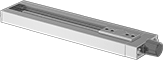
Use these slides in a variety of manual-positioning applications for laboratory and production equipment as well as for positioning parts for drilling, fastening, assembly, and measuring. Their Rulon plain bearings allow smooth movement in dirty environments.
Note: Capacities listed are for horizontal mounting. When mounted vertically, the load capacity is cut in half.
Travel Distance per Turn—Travel distance per turn, also known as screw lead, is the distance the carriage moves with one revolution of the handle.
Overall | Carriage | Handle | Carriage Mounting | Base Mounting | ||||||||||||||||
|---|---|---|---|---|---|---|---|---|---|---|---|---|---|---|---|---|---|---|---|---|
Travel Lg. | Travel Distance per Turn | Accuracy for Travel Distance per Turn | Ht. | Wd. | Lg. | Wd. | Lg. | Type | Dia. | Overhang | Max. Temp., ° F | No. of Holes | Hole Thread Size | No. of Holes | For Fastener Thread Size | Mounting Fasteners Included | Each | |||
Aluminum Carriage and Base | ||||||||||||||||||||
15 lb. Static Load Capacity | ||||||||||||||||||||
| 1.5" | 0.05" | 0.0007"/1" | 0.56" | 1.5" | 4.16" | 0.62" | 1.5" | Dial | 0.61" | — | 180 | 4 | 6-32 | 2 | 8-32 | No | 5236A15 | 0000000 | ||
| 4.5" | 0.05" | 0.0007"/1" | 0.56" | 1.5" | 7.16" | 0.62" | 1.5" | Dial | 0.61" | — | 180 | 4 | 6-32 | 2 | 8-32 | No | 5236A16 | 000000 | ||
| 7.5" | 0.05" | 0.0007"/1" | 0.56" | 1.5" | 10.16" | 0.62" | 1.5" | Dial | 0.61" | — | 180 | 4 | 6-32 | 3 | 8-32 | No | 5236A17 | 000000 | ||
| 10.5" | 0.05" | 0.0007"/1" | 0.56" | 1.5" | 13.16" | 0.62" | 1.5" | Dial | 0.61" | — | 180 | 4 | 6-32 | 4 | 8-32 | No | 5236A18 | 000000 | ||
30 lb. Static Load Capacity | ||||||||||||||||||||
| 1.5" | 0.05" | 0.0007"/1" | 0.81" | 2.5" | 6.72" | 1.25" | 2.5" | Hand Wheel | 1.75" | 0.44" | 180 | 4 | 8-32 | 2 | 10-32 | No | 5236A22 | 000000 | ||
| 3.5" | 0.05" | 0.0007"/1" | 0.81" | 2.5" | 8.72" | 1.25" | 2.5" | Hand Wheel | 1.75" | 0.44" | 180 | 4 | 8-32 | 2 | 10-32 | No | 5236A23 | 000000 | ||
| 6.5" | 0.05" | 0.0007"/1" | 0.81" | 2.5" | 11.72" | 1.25" | 2.5" | Hand Wheel | 1.75" | 0.44" | 180 | 4 | 8-32 | 3 | 10-32 | No | 5236A24 | 000000 | ||
| 9.5" | 0.05" | 0.0007"/1" | 0.81" | 2.5" | 14.72" | 1.25" | 2.5" | Hand Wheel | 1.75" | 0.44" | 180 | 4 | 8-32 | 4 | 10-32 | No | 5236A34 | 000000 | ||
| 12.5" | 0.05" | 0.0007"/1" | 0.81" | 2.5" | 17.72" | 1.25" | 2.5" | Hand Wheel | 1.75" | 0.44" | 180 | 4 | 8-32 | 5 | 10-32 | No | 5236A35 | 000000 | ||
100 lb. Static Load Capacity | ||||||||||||||||||||
| 2" | 0.1" | 0.0007"/1" | 1.06" | 4" | 8.73" | 2.35" | 4" | Hand Wheel | 1.75" | 0.24" | 180 | 4 | 10-32 | 2 | 1/4"-20 | No | 5236A27 | 000000 | ||
| 5" | 0.1" | 0.0007"/1" | 1.06" | 4" | 11.73" | 2.35" | 4" | Hand Wheel | 1.75" | 0.24" | 180 | 4 | 10-32 | 3 | 1/4"-20 | No | 5236A29 | 000000 | ||
| 8" | 0.1" | 0.0007"/1" | 1.06" | 4" | 14.73" | 2.35" | 4" | Hand Wheel | 1.75" | 0.24" | 180 | 4 | 10-32 | 4 | 1/4"-20 | No | 5236A31 | 000000 | ||
| 11" | 0.1" | 0.0007"/1" | 1.06" | 4" | 17.73" | 2.35" | 4" | Hand Wheel | 1.75" | 0.24" | 180 | 4 | 10-32 | 5 | 1/4"-20 | No | 5236A32 | 000000 | ||
| 14" | 0.1" | 0.0007"/1" | 1.06" | 4" | 20.73" | 2.35" | 4" | Hand Wheel | 1.75" | 0.24" | 180 | 4 | 10-32 | 6 | 1/4"-20 | No | 5236A33 | 000000 | ||
| 20" | 0.1" | 0.0007"/1" | 1.06" | 4" | 26.73" | 2.35" | 4" | Hand Wheel | 1.75" | 0.24" | 180 | 4 | 10-32 | 8 | 1/4"-20 | No | 5236A38 | 00000000 | ||
High-Load Positioning Slides
 |
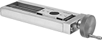
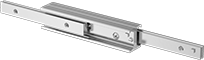
Made with Frelon bearings, these slides have over four times the load capacity of standard positioning slides. They have a precision lead screw for use in a variety of manual-positioning applications for laboratory and production equipment as well as for positioning parts for drilling, fastening, assembly, and measuring.
Note: Capacities listed are for horizontal mounting only.
Travel Distance per Turn—Travel distance per turn, also known as screw lead, is the distance the carriage moves with one revolution of the handle.
Mounting Plates—Two-axis mounting plates (sold separately) let you mount two slides together for motion along two axes.
Positioning Slides | Mounting Plates | ||||||||||||||||||||
|---|---|---|---|---|---|---|---|---|---|---|---|---|---|---|---|---|---|---|---|---|---|
Overall, mm | Carriage, mm | Handle | Carriage Mounting | Base Mounting | |||||||||||||||||
Travel Lg. | Travel Distance per Turn | Accuracy for Travel Distance per Turn | Ht., mm | Wd. | Lg. | Wd. | Lg. | Type | Dia., mm | Max. Temp., ° F | No. of Holes | Hole Thread Size | No. of Holes | For Fastener Thread Size | Mounting Fasteners Included | Each | Each | ||||
Aluminum Carriage and Base | |||||||||||||||||||||
490 lb. Static Load Capacity | |||||||||||||||||||||
| 4.35" | 0.05" | ±0.0006"/1" | 16 | 46 | 188.4 | 46 | 42 | Dial | 10.3 | 175 | 4 | M3 × 0.5 mm | 4 | M3 | No | 9222T11 | 000000000 | 9222T41 | 000000 | ||
| 10.35" | 0.05" | ±0.0006"/1" | 16 | 46 | 340.6 | 46 | 42 | Dial | 10.3 | 175 | 4 | M3 × 0.5 mm | 8 | M3 | No | 9222T12 | 000000 | 9222T41 | 00000 | ||
| 16.35" | 0.05" | ±0.0006"/1" | 16 | 46 | 489 | 46 | 42 | Dial | 10.3 | 175 | 4 | M3 × 0.5 mm | 12 | M3 | No | 9222T13 | 00000000 | 9222T41 | 00000 | ||
800 lb. Static Load Capacity | |||||||||||||||||||||
| 3.56" | 0.05" | ±0.0006"/1" | 25 | 46 | 187.9 | 46 | 62 | Dial | 18.3 | 175 | 4 | M4 × 0.7 mm | 3 | M5 | No | 9222T21 | 000000 | 9222T42 | 00000 | ||
| 9.56" | 0.05" | ±0.0006"/1" | 25 | 46 | 340.2 | 46 | 62 | Dial | 18.3 | 175 | 4 | M4 × 0.7 mm | 5 | M5 | No | 9222T22 | 000000 | 9222T42 | 00000 | ||
| 15.56" | 0.05" | ±0.0006"/1" | 25 | 46 | 492.6 | 46 | 62 | Dial | 18.3 | 175 | 4 | M4 × 0.7 mm | 8 | M5 | No | 9222T23 | 000000 | 9222T42 | 00000 | ||
Precision Positioning Slides
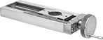 | |
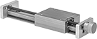
A linear scale and micrometer-like hand wheel measure travel distance in increments of 0.001". Rulon plain bearings allow these slides to move smoothly, even in dirty environments. Use them in a variety of manual-positioning applications for laboratory and production equipment as well as for positioning parts for drilling, fastening, assembly, and measuring.
Note: Capacities listed are for horizontal mounting. When mounted vertically, the load capacity is cut in half.
Travel Distance per Turn—Travel distance per turn, also known as screw lead, is the distance the carriage moves with one revolution of the handle.
Overall | Carriage | Handle | Carriage Mounting | Base Mounting | |||||||||||||||||
|---|---|---|---|---|---|---|---|---|---|---|---|---|---|---|---|---|---|---|---|---|---|
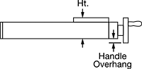
Travel Lg. | Travel Distance per Turn | Accuracy for Travel Distance per Turn | Ht. | Wd. | Lg. | Wd. | Lg. | Type | Dia. | Overhang | Linear Scale Graduations | Max. Temp., ° F | No. of Holes | Hole Thread Size | No. of Holes | For Fastener Thread Size | Mounting Fasteners Included | Each | |||
Aluminum Carriage and Base | |||||||||||||||||||||
15 lb. Static Load Capacity | |||||||||||||||||||||
| 1.5" | 0.05" | 0.00015"/1" | 0.61" | 1.5" | 5.6" | 0.62" | 1.5" | Hand Wheel | 1.75" | 0.59" | 0.025" | 180 | 4 | 6-32 | 2 | 8-32 | No | 5242A14 | 0000000 | ||
| 4.5" | 0.05" | 0.00015"/1" | 0.56" | 1.5" | 8.6" | 0.62" | 1.5" | Hand Wheel | 1.75" | 0.59" | 0.025" | 180 | 4 | 6-32 | 2 | 8-32 | No | 5242A11 | 000000 | ||
| 7.5" | 0.05" | 0.00015"/1" | 0.61" | 1.5" | 11.6" | 0.62" | 1.5" | Hand Wheel | 1.75" | 0.59" | 0.025" | 180 | 4 | 6-32 | 3 | 8-32 | No | 5242A12 | 000000 | ||
| 10.5" | 0.05" | 0.00015"/1" | 0.61" | 1.5" | 14.6" | 0.62" | 1.5" | Hand Wheel | 1.75" | 0.59" | 0.025" | 180 | 4 | 6-32 | 4 | 8-32 | No | 5242A13 | 000000 | ||
30 lb. Static Load Capacity | |||||||||||||||||||||
| 1.5" | 0.05" | 0.00015"/1" | 0.81" | 2.5" | 6.74" | 1.25" | 2.5" | Hand Wheel | 1.75" | 0.44" | 0.025" | 180 | 4 | 8-32 | 2 | 10-32 | No | 5242A19 | 000000 | ||
| 3.5" | 0.05" | 0.00015"/1" | 0.81" | 2.5" | 8.74" | 1.25" | 2.5" | Hand Wheel | 1.75" | 0.44" | 0.025" | 180 | 4 | 8-32 | 2 | 10-32 | No | 5242A21 | 000000 | ||
| 6.5" | 0.05" | 0.00015"/1" | 0.81" | 2.5" | 11.74" | 1.25" | 2.5" | Hand Wheel | 1.75" | 0.44" | 0.025" | 180 | 4 | 8-32 | 3 | 10-32 | No | 5242A22 | 000000 | ||
100 lb. Static Load Capacity | |||||||||||||||||||||
| 2" | 0.1" | 0.00015"/1" | 1.06" | 4" | 9.41" | 2.35" | 4" | Hand Wheel | 1.75" | 0.24" | 0.025" | 180 | 4 | 10-32 | 2 | 1/4"-20 | No | 5242A31 | 000000 | ||
| 5" | 0.1" | 0.00015"/1" | 1.06" | 4" | 12.41" | 2.35" | 4" | Hand Wheel | 1.75" | 0.24" | 0.025" | 180 | 4 | 10-32 | 3 | 1/4"-20 | No | 5242A32 | 00000000 | ||
| 8" | 0.1" | 0.00015"/1" | 1.06" | 4" | 15.41" | 2.35" | 4" | Hand Wheel | 1.75" | 0.24" | 0.025" | 180 | 4 | 10-32 | 4 | 1/4"-20 | No | 5242A33 | 00000000 | ||
| 11" | 0.1" | 0.00015"/1" | 1.06" | 4" | 18.41" | 2.35" | 4" | Hand Wheel | 1.75" | 0.24" | 0.025" | 180 | 4 | 10-32 | 5 | 1/4"-20 | No | 5242A34 | 00000000 | ||
| 14" | 0.1" | 0.00015"/1" | 1.06" | 4" | 21.41" | 2.35" | 4" | Hand Wheel | 1.75" | 0.24" | 0.025" | 180 | 4 | 10-32 | 6 | 1/4"-20 | No | 5242A35 | 00000000 | ||
Telescoping Rails
C Rail Profile
 | 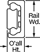 |
C Rail Profile |
Carriage Mounting | Rail Mounting | ||||||||||||
|---|---|---|---|---|---|---|---|---|---|---|---|---|---|
Rail Lg., mm | Travel Lg., mm | Dynamic Load Cap., lb. | Overall Ht., mm | Max. Temp., ° F | No. of Holes | Hole Thread Size | No. of Holes | For Fastener Thread Size | Mounting Fasteners Included | Each | |||
Zinc-Plated Steel Carriage and Steel Rail | |||||||||||||
22 mm Wide Rail | |||||||||||||
| 130 | 76 | 70 | 11 | 335 | 2 | M4 × 0.7 mm | 2 | M4 | No | 8379K31 | 0000000 | ||
| 210 | 111 | 160 | 11 | 335 | 3 | M4 × 0.7 mm | 3 | M4 | No | 8379K32 | 000000 | ||
| 370 | 196 | 287 | 11 | 335 | 5 | M4 × 0.7 mm | 5 | M4 | No | 8379K33 | 000000 | ||
28 mm Wide Rail | |||||||||||||
| 290 | 148 | 434 | 13 | 335 | 4 | M5 × 0.8 mm | 4 | M5 | No | 8379K35 | 000000 | ||
| 450 | 232 | 664 | 13 | 335 | 6 | M5 × 0.8 mm | 6 | M5 | No | 8379K36 | 000000 | ||
| 610 | 315 | 893 | 13 | 335 | 8 | M5 × 0.8 mm | 8 | M5 | No | 8379K37 | 000000 | ||
| 770 | 399 | 1,123 | 13 | 335 | 10 | M5 × 0.8 mm | 10 | M5 | No | 8379K38 | 000000 | ||
| 930 | 475 | 1,424 | 13 | 335 | 12 | M5 × 0.8 mm | 12 | M5 | No | 8379K39 | 000000 | ||
| 1,010 | 517 | 1,539 | 13 | 335 | 13 | M5 × 0.8 mm | 13 | M5 | No | 8379K11 | 000000 | ||
43 mm Wide Rail | |||||||||||||
| 610 | 313 | 1,666 | 22 | 335 | 8 | M8 × 1.25 mm | 8 | M8 | No | 8379K312 | 000000 | ||
| 930 | 483 | 2,485 | 22 | 335 | 12 | M8 × 1.25 mm | 12 | M8 | No | 8379K314 | 000000 | ||
| 1,010 | 518 | 2,795 | 22 | 335 | 13 | M8 × 1.25 mm | 13 | M8 | No | 8379K315 | 000000 | ||
| 1,330 | 688 | 3,613 | 22 | 335 | 17 | M8 × 1.25 mm | 17 | M8 | No | 8379K316 | 000000 | ||
| 1,490 | 758 | 4,236 | 22 | 335 | 19 | M8 × 1.25 mm | 19 | M8 | No | 8379K317 | 000000 | ||
Chrome-Plated Steel Carriage and Chrome-Plated Steel Rail | |||||||||||||
35 mm Wide Rail | |||||||||||||
| 210 | 129 | 578 | 17 | 212 | 3 | M6 × 1 mm | 3 | M6 | No | 8379K18 | 000000 | ||
| 290 | 158 | 898 | 17 | 212 | 4 | M6 × 1 mm | 4 | M6 | No | 8379K19 | 000000 | ||
| 370 | 200 | 967 | 17 | 212 | 5 | M6 × 1 mm | 5 | M6 | No | 8379K21 | 000000 | ||
| 450 | 254 | 895 | 17 | 212 | 6 | M6 × 1 mm | 6 | M6 | No | 8379K22 | 000000 | ||
| 530 | 284 | 1,047 | 17 | 212 | 7 | M6 × 1 mm | 7 | M6 | No | 8379K23 | 000000 | ||
| 610 | 326 | 1,072 | 17 | 212 | 8 | M6 × 1 mm | 8 | M6 | No | 8379K24 | 000000 | ||
| 690 | 367 | 1,094 | 17 | 212 | 9 | M6 × 1 mm | 9 | M6 | No | 8379K25 | 000000 | ||
Double C Rail Profile
 | 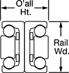 |
Double C Rail Profile |
Carriage Mounting | |||||||||||
|---|---|---|---|---|---|---|---|---|---|---|---|
Rail Lg., mm | Travel Lg., mm | Dynamic Load Cap., lb. | Overall Ht., mm | Max. Temp., ° F | No. of Holes | Hole Thread Size | Mounting Fasteners Included | Each | |||
Zinc-Plated Steel Carriage and Zinc-Plated Steel Rail | |||||||||||
28 mm Wide Rail | |||||||||||
| 130 | 148 | 52 | 26 | 335 | 2 | M5 × 0.8 mm | No | 4556N11 | 0000000 | ||
| 210 | 232 | 97 | 26 | 335 | 3 | M5 × 0.8 mm | No | 4556N12 | 000000 | ||
| 290 | 296 | 172 | 26 | 335 | 4 | M5 × 0.8 mm | No | 4556N13 | 000000 | ||
| 450 | 464 | 262 | 26 | 335 | 6 | M5 × 0.8 mm | No | 4556N15 | 000000 | ||
| 530 | 548 | 248 | 26 | 335 | 7 | M5 × 0.8 mm | No | 4556N16 | 000000 | ||
| 610 | 633 | 214 | 26 | 335 | 8 | M5 × 0.8 mm | No | 4556N17 | 000000 | ||
43 mm Wide Rail | |||||||||||
| 370 | 416 | 292 | 44 | 335 | 5 | M8 × 1.25 mm | No | 4556N47 | 000000 | ||
| 450 | 486 | 410 | 44 | 335 | 6 | M8 × 1.25 mm | No | 4556N48 | 000000 | ||
| 530 | 556 | 533 | 44 | 335 | 7 | M8 × 1.25 mm | No | 4556N49 | 000000 | ||
| 610 | 626 | 659 | 44 | 335 | 8 | M8 × 1.25 mm | No | 4556N51 | 000000 | ||
| 690 | 726 | 694 | 44 | 335 | 9 | M8 × 1.25 mm | No | 4556N52 | 000000 | ||
| 850 | 866 | 640 | 44 | 335 | 11 | M8 × 1.25 mm | No | 4556N54 | 00000000 | ||
| 1,090 | 1,106 | 503 | 44 | 335 | 14 | M8 × 1.25 mm | No | 4556N57 | 00000000 | ||
Telescoping Rail Sets
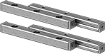 | 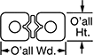 |
Create your own positioning table or telescoping slide.
Overall, mm | Mounting | |||||||||||||
|---|---|---|---|---|---|---|---|---|---|---|---|---|---|---|
Rail Lg., mm | Travel Lg., mm | Dynamic Load Cap., lb. | Wd. | Ht. | Max. Temp., ° F | No. of Holes per Rail | Hole Thread Size | Fasteners Included | Features | Includes | Each | |||
Steel Rail | ||||||||||||||
| 75 | 50 | 290 | 18 | 8 | 175 | 3 | M4 × 0.7 mm | No | — | Four Rails Two Roller Bearing Cages Eight End Stops | 6500K16 | 0000000 | ||
| 100 | 70 | 380 | 18 | 8 | 175 | 4 | M4 × 0.7 mm | No | — | Four Rails Two Roller Bearing Cages Eight End Stops | 6500K17 | 000000 | ||
| 150 | 100 | 580 | 18 | 8 | 175 | 6 | M4 × 0.7 mm | No | — | Four Rails Two Roller Bearing Cages Eight End Stops | 6500K18 | 000000 | ||
440 Stainless Steel Rail | ||||||||||||||
| 90 | 42 | 750 | 12 | 6 | 210 | 6 | M3 × 0.5 mm | No | Stabilizing Gear | Four Rails Two Roller Bearing Cages Eight End Stops | 6500K71 | 000000 | ||
| 150 | 66 | 2,550 | 18 | 8 | 210 | 6 | M4 × 0.7 mm | No | Stabilizing Gear | Four Rails Two Roller Bearing Cages Eight End Stops | 6500K72 | 000000 | ||
| 200 | 101 | 5,300 | 22 | 11 | 210 | 5 | M5 × 0.8 mm | No | Stabilizing Gear | Four Rails Two Roller Bearing Cages Eight End Stops | 6500K73 | 000000 | ||
