


Filter by
Position Designation
Actuator Style


System of Measurement
Illumination
Switch Action
Push-Button Shape

Switch Starting Position
Wire Connection

Mount Type

Enclosure Rating
Mounting Location
U.S.–Mexico–Canada Agreement (USMCA) Qualifying
DFARS Specialty Metals
Export Control Classification Number (ECCN)

About Electrical Switches
Choose a switch with the right trigger type, number of inputs, and control functions to power your equipment.
Rocker Switches
 |  |
Style A | Style D |
The wide surface of these switches makes them easy to press on and off, even if your hands are full and you need to use an elbow. They’re often used as power switches on electronic devices and control panels.
Note: Illuminated switches include a bulb. If wiring the switch and the bulb to the same circuit, the circuit voltage must not exceed the bulb voltage.
Illuminated—Illuminated switches are easy to see in dim and dark areas. They come in red and green, so you can color code your set up.
For 13/16" Diameter Panel Cutouts—Switches for a 13/16” dia. panel cutout are round, so you can use a drill bit or knockout to install them instead of cutting a rectangular hole.
On-On—Switches with an on-on position designation alternate power between sets of terminals.
Style | No. of Circuits Controlled | Switch Starting Position | Switch Action | No. of Terminals | Switch Designation | Position Designation | Switching Current @ Voltage | Max. Voltage, V AC | Bulb Voltage, V AC | Quick-Disconnect Tab Wd. | Bulb Type | Choose a Color | Each | |||
|---|---|---|---|---|---|---|---|---|---|---|---|---|---|---|---|---|
2 Positions with Quick-Disconnect Terminals | ||||||||||||||||
For 13/16" Diameter Panel Cutouts | ||||||||||||||||
| A | 1 | 1 Off | Maintained | 3 | SPST-NO | On-On | 10 amp @ 125V AC | 125 | — | 0.189" | — | Black | 7395K127 | 00000 | ||
| A | 1 | 1 Off | Maintained | 3 | SPST-NO | On-On | 16 amp @ 125V AC, 10 amp @ 250V AC | 250 | — | 0.189" | — | Black | 7395K129 | 0000 | ||
| A | 1 | 1 On | Maintained | 2 | SPST-NC | On-Off | 10 amp @ 125V AC | 125 | — | 0.189" | — | Black | 7395K126 | 0000 | ||
| A | 1 | 1 On | Maintained | 2 | SPST-NC | On-Off | 16 amp @ 125V AC, 10 amp @ 250V AC | 250 | — | 0.189" | — | Black | 7395K128 | 0000 | ||
2 Positions with Quick-Disconnect Terminals—Illuminated | ||||||||||||||||
For 13/16" Diameter Panel Cutouts | ||||||||||||||||
| D | 1 | 1 On | Maintained | 3 | SPST-NC | On-Off | 16 amp @ 125V AC, 10 amp @ 250V AC | 250 | 125 | 0.189" | Neon | Green, Red | 7395K103 | 0000 | ||
3 Positions with Quick-Disconnect Terminals | ||||||||||||||||
For 13/16" Diameter Panel Cutouts | ||||||||||||||||
| A | 1 | 1 Off | Maintained | 3 | SPST-NO | On-Off-On | 16 amp @ 125V AC, 10 amp @ 250V AC | 250 | — | 0.189" | — | Black | 7395K135 | 0000 | ||
Cable-Pull-Actuator Emergency Stop Switches with Restart Switch
1 Direction
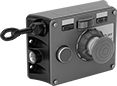 | 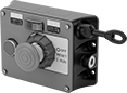 |
Left Side Cable Location | Right Side Cable Location |
Mounting | |||||||||||||||||
|---|---|---|---|---|---|---|---|---|---|---|---|---|---|---|---|---|---|
Cable Location | For Max. Cable Lg., ft. | No. of Circuits Controlled | Switch Starting Position | No. of Terminals | Switch Designation | Switching Current @ Voltage | Max. Voltage | Actuation Force, lbf | Conduit Trade Size | Bulb Voltage | Fasteners Included | No. of Holes | Hole Dia. | Each | |||
Screw-Terminal Wire Connection | |||||||||||||||||
With Emergency Stop Button, Power Indicator, Restart Button, Tension Indicator (IP54, NEMA 1) | |||||||||||||||||
| Left Side | 325 | 2 | 2 Off or 2 On | 6 | DPDT | 6 amp @ 120V AC 2.8 amp @ 24V DC | 240V AC 24V DC | 11 | 1/2 | 24V DC | No | 4 | 1/4" | 5746N301 | 000000000 | ||
| Left Side | 325 | 2 | 2 Off or 2 On | 6 | DPDT | 6 amp @ 120V AC 2.8 amp @ 24V DC | 240V AC 24V DC | 11 | 1/2 | 120V AC | No | 4 | 1/4" | 5746N201 | 00000000 | ||
| Right Side | 325 | 2 | 2 Off or 2 On | 6 | DPDT | 6 amp @ 120V AC 2.8 amp @ 24V DC | 240V AC 24V DC | 11 | 1/2 | 24V DC | No | 4 | 1/4" | 5746N11 | 00000000 | ||
| Right Side | 325 | 2 | 2 Off or 2 On | 6 | DPDT | 6 amp @ 120V AC 2.8 amp @ 24V DC | 240V AC 24V DC | 11 | 1/2 | 120V AC | No | 4 | 1/4" | 5746N202 | 00000000 | ||
2 Directions
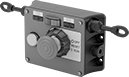 |
Two-direction switches support twice the total cable distance of one-direction switches. With pulls on each side, you can route cable in two opposite directions. These switches are often placed at the midpoint of conveyors and other long runs of equipment.
Mounting | |||||||||||||||||
|---|---|---|---|---|---|---|---|---|---|---|---|---|---|---|---|---|---|
Cable Location | For Max. Cable Lg., ft. | No. of Circuits Controlled | Switch Starting Position | No. of Terminals | Switch Designation | Switching Current @ Voltage | Max. Voltage | Actuation Force, lbf | Conduit Trade Size | Bulb Voltage | Fasteners Included | No. of Holes | Hole Dia. | Each | |||
Screw-Terminal Wire Connection | |||||||||||||||||
With Emergency Stop Button, Power Indicator, Restart Button, Tension Indicator (IP54, NEMA 1) | |||||||||||||||||
| Left Side, Right Side | 325 | 2 | 2 Off or 2 On | 6 | DPDT | 6 amp @ 120V AC 2.8 amp @ 24V DC | 240V AC 24V DC | 11 | 1/2 | 24V DC | No | 4 | 1/4" | 5746N12 | 000000000 | ||
| Left Side, Right Side | 325 | 2 | 2 Off or 2 On | 6 | DPDT | 6 amp @ 120V AC 2.8 amp @ 24V DC | 240V AC 24V DC | 11 | 1/2 | 120V AC | No | 4 | 1/4" | 5746N204 | 000000 | ||
Tablet Holders with Emergency Stop Switch
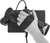 | 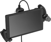 |
Pivoting Handle (Back View) | Holder with Tablet Installed (Not Included) |
 |  |
Holder | Tablet Holder Bracket Kits |
Halt machinery in an instant with these tablet holders. They equip your tablet with safety switches that meet IEC and EN standards, so you can safely move around your equipment while teaching robots or monitoring production lines and conveyor systems.
The emergency stop switch on the front of the holder illuminates when the switch is enabled. There is also a deadman switch on the back of the holder that controls machinery when you lightly press and hold it in the middle position. If the switch is released or pressed down all the way, it stops the machine.
Pivot the handle to hold a tablet vertically or horizontally, while keeping the switches in a comfortable position for either hand. The adjustable mounting bracket secures a variety of tablet sizes. Connect your tablet to the USB port to charge during use.
Tablet Holder Bracket Kits—Tablet holder bracket kits enlarge the bracket to hold tablets with thick covers and protectors.
