


About Motor Switches and Starters
More
Choosing an Electrical Switch
More
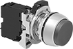
Metal 22 mm Panel-Mount Push-Button Switches
Simple to use, these switches actuate with a quick push. They mount in a standard panel cutout diameter. Switches include enough contact blocks to control the number of circuits listed. Color code your switches by choosing a different actuator color for each.
Illuminated switches are easy to see in dim and dark areas.
Switches with an arrow message can be installed with the arrow oriented up, down, left, or right.
NEMA or IP rated, all switches protect against dust. NEMA 4, IP65, and IP66 rated switches seal out water from washdowns. NEMA 13 rated switches withstand splashing water, oil, and coolant.
Note: Illuminated switches include a bulb. If wiring the switch and the bulb to the same circuit, the circuit voltage must not exceed bulb voltage.
Additional contact blocks (sold separately) can be added to control more circuits, or replace the included contact block.
![]() For technical drawings and 3-D models, click on a part number.
For technical drawings and 3-D models, click on a part number.


| No. of Circuits Controlled | Switch Starting Position | Switch Action | No. of Terminals | Industry Designation | Message | Switching Current @ Voltage | Dia. | For Max. No. of Contact Blocks | Choose a Bulb Voltage | Choose an Actuator Color | Environmental Rating | Each | |
Round with Screw Terminals— (600V AC/600V DC Max. Voltage) | |||||||||||||
|---|---|---|---|---|---|---|---|---|---|---|---|---|---|
Flush | |||||||||||||
| 1 | 1 Off (Normally Open) | Springs Back (Momentary) | 2 | SPST-NO | __ | 6 A @ 120 V AC, 2.5 A @ 24 V DC | 1 3/16" | 6 | __ | NEMA 4, NEMA 13, IP66 | 0000000 | 000000 | |
| 1 | 1 Off (Normally Open) | Springs Back (Momentary) | 2 | SPST-NO | Arrow | 6 A @ 120 V AC, 2.5 A @ 24 V DC | 1 3/16" | 6 | __ | NEMA 4, NEMA 13, IP66 | 00000000 | 00000 | |
| 1 | 1 Off (Normally Open) | Springs Back (Momentary) | 2 | SPST-NO | Forward | 6 A @ 120 V AC, 2.5 A @ 24 V DC | 1 3/16" | 6 | __ | NEMA 4, NEMA 13, IP66 | 00000000 | 00000 | |
| 1 | 1 Off (Normally Open) | Springs Back (Momentary) | 2 | SPST-NO | R | 6 A @ 120 V AC, 2.5 A @ 24 V DC | 1 3/16" | 6 | __ | NEMA 4, NEMA 13, IP66 | 00000000 | 00000 | |
| 1 | 1 Off (Normally Open) | Springs Back (Momentary) | 2 | SPST-NO | Reverse | 6 A @ 120 V AC, 2.5 A @ 24 V DC | 1 3/16" | 6 | __ | NEMA 4, NEMA 13, IP66 | 00000000 | 00000 | |
| 1 | 1 Off (Normally Open) | Springs Back (Momentary) | 2 | SPST-NO | Start | 6 A @ 120 V AC, 2.5 A @ 24 V DC | 1 3/16" | 6 | __ | NEMA 4, NEMA 13, IP66 | 00000000 | 00000 | |
| 1 | 1 Off (Normally Open) | Springs Back (Momentary) | 2 | SPST-NO | Vertical Line | 6 A @ 120 V AC, 2.5 A @ 24 V DC | 1 3/16" | 6 | __ | NEMA 4, NEMA 13, IP66 | 00000000 | 00000 | |
| 1 | 1 Off (Normally Open) | Stays Switched (Maintained) | 2 | SPST-NO | __ | 6 A @ 120 V AC, 2.5 A @ 24 V DC | 1 3/16" | 6 | __ | NEMA 4, NEMA 13, IP66 | 0000000 | 00000 | |
| 1 | 1 Off (Normally Open) | Stays Switched (Maintained) | 2 | SPST-NO | __ | 6 A @ 120 V AC, 2.5 A @ 24 V DC | 1 3/16" | 6 | __ | NEMA 4, NEMA 13, IP66 | 0000000 | 00000 | |
| 1 | 1 On (Normally Closed) | Springs Back (Momentary) | 2 | SPST-NC | __ | 6 A @ 120 V AC, 2.5 A @ 24 V DC | 1 3/16" | 6 | __ | NEMA 4, NEMA 13, IP66 | 0000000 | 00000 | |
| 1 | 1 On (Normally Closed) | Springs Back (Momentary) | 2 | SPST-NC | Circle | 6 A @ 120 V AC, 2.5 A @ 24 V DC | 1 3/16" | 6 | __ | Red | NEMA 4, NEMA 13, IP66 | 00000000 | 00000 |
| 1 | 1 On (Normally Closed) | Springs Back (Momentary) | 2 | SPST-NC | Stop | 6 A @ 120 V AC, 2.5 A @ 24 V DC | 1 3/16" | 6 | __ | Red | NEMA 4, NEMA 13, IP66 | 00000000 | 00000 |
| 1 | 1 On (Normally Closed) | Stays Switched (Maintained) | 2 | SPST-NC | __ | 6 A @ 120 V AC, 2.5 A @ 24 V DC | 1 3/16" | 6 | __ | NEMA 4, NEMA 13, IP66 | 0000000 | 00000 | |
| 2 | 1 Off (Normally Open) and 1 On (Normally Closed) | Springs Back (Momentary) | 4 | DPST-1NO/1NC | __ | 6 A @ 120 V AC, 2.5 A @ 24 V DC | 1 3/16" | 6 | __ | NEMA 4, NEMA 13, IP66 | 0000000 | 00000 | |
Projecting | |||||||||||||
| 1 | 1 Off (Normally Open) | Springs Back (Momentary) | 2 | SPST-NO | __ | 6 A @ 120 V AC, 2.5 A @ 24 V DC | 1 3/16" | 6 | __ | NEMA 4, NEMA 13, IP66 | 0000000 | 00000 | |
| 1 | 1 Off (Normally Open) | Springs Back (Momentary) | 2 | SPST-NO | Arrow | 6 A @ 120 V AC, 2.5 A @ 24 V DC | 1 3/16" | 6 | __ | NEMA 4, NEMA 13, IP66 | 00000000 | 00000 | |
| 1 | 1 Off (Normally Open) | Springs Back (Momentary) | 2 | SPST-NO | R | 6 A @ 120 V AC, 2.5 A @ 24 V DC | 1 3/16" | 6 | __ | NEMA 4, NEMA 13, IP66 | 00000000 | 00000 | |
| 1 | 1 Off (Normally Open) | Springs Back (Momentary) | 2 | SPST-NO | Vertical Line | 6 A @ 120 V AC, 2.5 A @ 24 V DC | 1 3/16" | 6 | __ | White | NEMA 4, NEMA 13, IP66 | 00000000 | 00000 |
| 1 | 1 On (Normally Closed) | Springs Back (Momentary) | 2 | SPST-NC | __ | 6 A @ 120 V AC, 2.5 A @ 24 V DC | 1 3/16" | 6 | __ | NEMA 4, NEMA 13, IP66 | 0000000 | 00000 | |
| 1 | 1 On (Normally Closed) | Springs Back (Momentary) | 2 | SPST-NC | Circle | 6 A @ 120 V AC, 2.5 A @ 24 V DC | 1 3/16" | 6 | __ | NEMA 4, NEMA 13, IP66 | 00000000 | 00000 | |
| 1 | 1 On (Normally Closed) | Springs Back (Momentary) | 2 | SPST-NC | Stop | 6 A @ 120 V AC, 2.5 A @ 24 V DC | 1 3/16" | 6 | __ | NEMA 4, NEMA 13, IP66 | 00000000 | 00000 | |
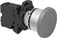
Mushroom | |||||||||||||
| 1 | 1 Off (Normally Open) | Springs Back (Momentary) | 2 | SPST-NO | __ | 6 A @ 120 V AC, 2.5 A @ 24 V DC | 1 9/16" | 6 | __ | NEMA 4, NEMA 13, IP65 | 0000000 | 00000 | |
| 1 | 1 Off (Normally Open) | Springs Back (Momentary) | 2 | SPST-NO | __ | 6 A @ 120 V AC, 2.5 A @ 24 V DC | 2 3/8" | 6 | __ | NEMA 4, NEMA 13, IP65 | 0000000 | 00000 | |
| 1 | 1 On (Normally Closed) | Springs Back (Momentary) | 2 | SPST-NC | __ | 6 A @ 120 V AC, 2.5 A @ 24 V DC | 1 9/16" | 6 | __ | NEMA 4, NEMA 13, IP65 | 0000000 | 00000 | |
| 1 | 1 On (Normally Closed) | Springs Back (Momentary) | 2 | SPST-NC | __ | 6 A @ 120 V AC, 2.5 A @ 24 V DC | 2 3/8" | 6 | __ | NEMA 4, NEMA 13, IP65 | 0000000 | 00000 | |
| 2 | 1 Off (Normally Open) and 1 On (Normally Closed) | Springs Back (Momentary) | 4 | DPST-1NO/1NC | __ | 6 A @ 120 V AC, 2.5 A @ 24 V DC | 1 9/16" | 6 | __ | NEMA 4, NEMA 13, IP65 | 0000000 | 00000 | |
Round with Screw Terminals—Illuminated (600V AC/600V DC Max. Voltage) | |||||||||||||
Flush | |||||||||||||
| 1 | 1 Off (Normally Open) | Springs Back (Momentary) | 2 | SPST-NO | __ | 6 A @ 120 V AC, 2.5 A @ 24 V DC | 1 3/16" | 4 | NEMA 4, NEMA 13, IP66 | 0000000 | 00000 | ||
| 1 | 1 Off (Normally Open) | Stays Switched (Maintained) | 2 | SPST-NO | __ | 6 A @ 120 V AC, 2.5 A @ 24 V DC | 1 3/16" | 4 | NEMA 4, NEMA 13, IP66 | 0000000 | 00000 | ||
| 1 | 1 On (Normally Closed) | Springs Back (Momentary) | 2 | SPST-NC | __ | 6 A @ 120 V AC, 2.5 A @ 24 V DC | 1 3/16" | 4 | NEMA 4, NEMA 13, IP66 | 0000000 | 00000 | ||
| 1 | 1 On (Normally Closed) | Stays Switched (Maintained) | 2 | SPST-NC | __ | 6 A @ 120 V AC, 2.5 A @ 24 V DC | 1 3/16" | 4 | NEMA 4, NEMA 13, IP66 | 0000000 | 00000 | ||
| 2 | 1 Off (Normally Open) and 1 On (Normally Closed) | Springs Back (Momentary) | 4 | DPST-1NO/1NC | __ | 6 A @ 120 V AC, 2.5 A @ 24 V DC | 1 3/16" | 4 | NEMA 4, NEMA 13, IP66 | 00000000 | 00000 | ||
Projecting | |||||||||||||
| 1 | 1 Off (Normally Open) | Springs Back (Momentary) | 2 | SPST-NO | __ | 6 A @ 120 V AC, 2.5 A @ 24 V DC | 1 3/16" | 4 | NEMA 4, NEMA 13, IP66 | 0000000 | 00000 | ||
| 1 | 1 On (Normally Closed) | Springs Back (Momentary) | 2 | SPST-NC | __ | 6 A @ 120 V AC, 2.5 A @ 24 V DC | 1 3/16" | 4 | NEMA 4, NEMA 13, IP66 | 0000000 | 00000 | ||
| 2 | 1 Off (Normally Open) and 1 On (Normally Closed) | Springs Back (Momentary) | 4 | DPST-1NO/1NC | __ | 6 A @ 120 V AC, 2.5 A @ 24 V DC | 1 3/16" | 4 | NEMA 4, NEMA 13, IP66 | 0000000 | 00000 | ||
Mushroom | |||||||||||||
| 1 | 1 Off (Normally Open) | Springs Back (Momentary) | 2 | SPST-NO | __ | 6 A @ 120 V AC, 2.5 A @ 24 V DC | 1 9/16" | 4 | NEMA 4, NEMA 13, IP65 | 0000000 | 00000 | ||
| 1 | 1 On (Normally Closed) | Springs Back (Momentary) | 2 | SPST-NC | __ | 6 A @ 120 V AC, 2.5 A @ 24 V DC | 1 9/16" | 4 | NEMA 4, NEMA 13, IP65 | 0000000 | 00000 | ||
| 2 | 1 Off (Normally Open) and 1 On (Normally Closed) | Springs Back (Momentary) | 4 | DPST-1NO/1NC | __ | 6 A @ 120 V AC, 2.5 A @ 24 V DC | 1 9/16" | 4 | NEMA 4, NEMA 13, IP65 | 0000000 | 00000 | ||

Make or break an electrical circuit. These contact blocks mount to manual switches and transmit an electrical signal when the switch actuator is engaged. You can stack multiple blocks, so a single switch can control several circuits. This is helpful in setups that require multiple systems to turn on or off at the same time. For example, the switch on a conveyor line could turn off the conveyor and turn on a diverter and alarm.
Wireless Self-Powered 22 mm Panel-Mount Push-Button Switches
Mount these switches in panel cutouts where changing a battery or routing wires might be difficult—they power themselves when you push the button. These switches wirelessly send a signal to a receiver (sold separately) up to 330 feet away. Since they operate equipment without requiring wires back to your control panel, they’re often used for retrofit or temporary installations. The switches come in distinct colors to help operators quickly identify them.
Switches include enough contact blocks to control the number of circuits listed. Additional contact blocks (sold separately) can be added to control more circuits or replace the included contact block. Connect up to 32 contact blocks to one receiver.
![]() For technical drawings and 3-D models, click on a part number.
For technical drawings and 3-D models, click on a part number.

| No. of Circuits Controlled | Max. Transmission Distance, ft. | Transmission Frequency | Switch Action | Dia. | For Max. Panel Thick. | Dp. Behind Panel | For Max. Number of Contact Blocks | Choose an Actuator Color | Environmental Rating | Each | |
Plastic Base | |||||||||||
|---|---|---|---|---|---|---|---|---|---|---|---|
| 1 | 330 | 2,405 MHz | Springs Back (Momentary) | 1 1/8" | 1/4" | 1 5/8" | 3 | IP66, IP67, IP69K | 0000000 | 0000000 | |


| No. of Circuits Controlled | Switch Starting Position | Number of Terminals | Industry Designation | Switching Current @ Voltage | Input Voltage | Max. Voltage | Mounting Location | For DIN Rail Size | Ht. | Wd. | Dp. | Environmental Rating | Each | |
Screw Terminals | ||||||||||||||
|---|---|---|---|---|---|---|---|---|---|---|---|---|---|---|
| 2 | 2 Off (Normally Open) or 2 On (Normally Closed) | 6 | DPDT | 5 mA @ 250 V AC, 5 mA @ 250 V DC | 24V AC-240V AC/24V DC-240V DC | 250V AC/250V DC | DIN Rail | 35 mm | 4 1/4" | 2 13/16" | 1 7/16" | IP20 | 0000000 | 0000000 |
Contact Blocks for Manual Switches

Make or break an electrical circuit. These contact blocks mount to manual switches and transmit an electrical signal when the switch actuator is engaged. You can stack multiple blocks, so a single switch can control several circuits. This is helpful in setups that require multiple systems to turn on or off at the same time. For example, the switch on a conveyor line could turn off the conveyor and turn on a diverter and alarm.
Quick-make blocks close the contacts milliseconds before the push-button or lever is fully actuated, so they’re often installed in safety systems. For example, you can connect one quick-make block and one standard block to a switch that controls two circuits—this ensures one contact turns on or off before the other.
| No. of Circuits Controlled | Switch Starting Position | No. of Terminals | Industry Designation | Wire Connection Type | Environmental Rating | For Switch Manufacturer Series | Each | |
C3 Controls | ||||||||
|---|---|---|---|---|---|---|---|---|
| 1 | 1 Off (Normally Open) | 2 | SPST-NO | Screw Terminals | __ | FVPPM, PBO, PTR, RLPPM | 00000000 | 000000 |
| 1 | 1 On (Normally Closed) | 2 | SPST-NC | Screw Terminals | __ | FVPPM, PBO, PTR, RLPPM | 00000000 | 00000 |
| 2 | 2 Off (Normally Open) | 4 | DPST-NO | Screw Terminals | __ | 22PP, 22PB | 0000000 | 00000 |
| 2 | 1 Off (Normally Open) and 1 On (Normally Closed) | 4 | DPST-1NO/1NC | Screw Terminals | __ | 22PP, 22PB | 0000000 | 00000 |
Schneider Electric | ||||||||
| 1 | 1 Off (Normally Open) | 2 | SPST-NO | Screw Terminals | IP20 | 9001K, 9001SK | 0000000 | 00000 |
| 1 | 1 On (Normally Closed) | 2 | SPST-NC | Screw Terminals | IP20 | XB5 | 0000000 | 00000 |
| 1 | 1 On (Normally Closed) | 2 | SPST-NC | Screw Terminals | IP20 | 9001K, 9001SK | 0000000 | 00000 |
| 2 | 1 Off (Normally Open) and 1 On (Normally Closed) | 4 | DPST-1NO/1NC | Screw Terminals | IP20 | 9001K, 9001SK | 0000000 | 00000 |
Sprecher & Schuh | ||||||||
| 1 | 1 On (Normally Closed) | 2 | SPST-NC | Screw Terminals | IP20 | D7M, D7P | 00000000 | 00000 |
Sprecher & Schuh—Quick Make | ||||||||
| 1 | 1 Off (Normally Open) | 2 | SPST-NO | Screw Terminals | IP20 | D7M, D7P | 00000000 | 00000 |
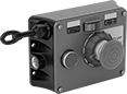
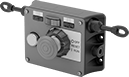
Cable-Pull Emergency Stop Switches with Restart Switch
Tug the cable to stop your line, then follow it back to the restart switch. Typically separate devices, the stop and reset controls are in one compact unit. As a secondary shutdown option, a push-button stop switch is also built in. A secondary push-button stop switch ensures you can halt equipment immediately, even when the cable is out of reach. Because they let you control circuits from a distance with a quick tug, these cable-pull stop switches are often used to turn off production lines and material handling systems. To notify your team on the floor that you’ve stopped equipment, a power indicator lights up when you pull the cable.
Use the tension indicator to confirm that cable is set up correctly. Circuits remain open until you tension the cable and hit the restart button. Cable is not included.
Two-direction switches support twice the total cable distance of one-direction switches. With pulls on each side, you can route cable in two opposite directions. These switches are often placed at the midpoint of conveyors and other long runs of equipment.
![]() For technical drawings and 3-D models, click on a part number.
For technical drawings and 3-D models, click on a part number.
Mounting | |||||||||||||||
|---|---|---|---|---|---|---|---|---|---|---|---|---|---|---|---|
| Cable Location | For Max. Cable Lg., ft. | No. of Circuits Controlled | Switch Starting Position | No. of Terminals | Industry Designation | Switching Current @ Voltage | Max. Voltage | Actuation Force, lbs. | Conduit Trade Size | Bulb Voltage | Fasteners Included | No. of Holes | Hole Dia. | Each | |
With Screw Terminals | |||||||||||||||
With Restart Button, Emergency Stop Button, Power Indicator and Tension Indicator (IP54, NEMA 1) | |||||||||||||||
| Left Side | 325 | 2 | 2 Off (Normally Open) or 2 On (Normally Closed) | 6 | DPDT | 6 A @ 120 V AC, 2.8 A @ 24 V DC | 240V AC 24V DC | 11 | 1/2 | 24V DC | No | 4 | 1/4" | 00000000 | 0000000 |
| Left Side | 325 | 2 | 2 Off (Normally Open) or 2 On (Normally Closed) | 6 | DPDT | 6 A @ 120 V AC, 2.8 A @ 24 V DC | 240V AC 24V DC | 11 | 1/2 | 120V AC | No | 4 | 1/4" | 00000000 | 00000000 |
| Right Side | 325 | 2 | 2 Off (Normally Open) or 2 On (Normally Closed) | 6 | DPDT | 6 A @ 120 V AC, 2.8 A @ 24 V DC | 240V AC 24V DC | 11 | 1/2 | 24V DC | No | 4 | 1/4" | 0000000 | 000000 |
| Right Side | 325 | 2 | 2 Off (Normally Open) or 2 On (Normally Closed) | 6 | DPDT | 6 A @ 120 V AC, 2.8 A @ 24 V DC | 240V AC 24V DC | 11 | 1/2 | 120V AC | No | 4 | 1/4" | 00000000 | 00000000 |
Mounting | ||||||||||||||
|---|---|---|---|---|---|---|---|---|---|---|---|---|---|---|
| For Max. Cable Lg., ft. | No. of Circuits Controlled | Switch Starting Position | No. of Terminals | Industry Designation | Switching Current @ Voltage | Max. Voltage | Actuation Force, lbs. | Conduit Trade Size | Bulb Voltage | Fasteners Included | No. of Holes | Hole Dia. | Each | |
With Screw Terminals | ||||||||||||||
With Restart Button, Emergency Stop Button, Power Indicator and Tension Indicator (IP54, NEMA 1) | ||||||||||||||
| 325 | 2 | 2 Off (Normally Open) or 2 On (Normally Closed) | 6 | DPDT | 6 A @ 120 V AC, 2.8 A @ 24 V DC | 240V AC 24V DC | 11 | 1/2 | 24V DC | No | 4 | 1/4" | 0000000 | 000000000 |
| 325 | 2 | 2 Off (Normally Open) or 2 On (Normally Closed) | 6 | DPDT | 6 A @ 120 V AC, 2.8 A @ 24 V DC | 240V AC 24V DC | 11 | 1/2 | 120V AC | No | 4 | 1/4" | 00000000 | 00000000 |
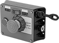
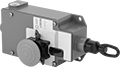
Cable-Pull Emergency Stop Switches
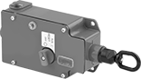
Emergency Stop Button,
Power and Tension Indicator
Immediately cut power by pulling a cable. These switches are often used to turn off production lines and material handling systems in an emergency. All have positive-force, snap-open contacts that open a circuit when actuated, even if a spring fails or the contacts stick. The contacts will remain open until you tension the cable and reset the switch.
Switches with a power indicator illuminate when the cable has been pulled.
Switches with a tension indicator let you visually confirm that tension is set correctly in the system.
Switches with an emergency stop button can be shut off either by their button or cable. They’re often installed where equipment may block access to the cable.
![]() For technical drawings and 3-D models, click on a part number.
For technical drawings and 3-D models, click on a part number.
Mounting | |||||||||||||
|---|---|---|---|---|---|---|---|---|---|---|---|---|---|
| For Max. Cable Lg., ft. | No. of Circuits Controlled | Switch Starting Position | No. of Terminals | Industry Designation | Switching Current @ Voltage | Max. Voltage | Actuation Force, lbs. | Conduit Trade Size | Fasteners Included | No. of Holes | Hole Dia. | Each | |
With Screw Terminals | |||||||||||||
1 Direction with Power Indicator and Tension Indicator (IP67, NEMA 4, NEMA 13) | |||||||||||||
| 250 | 1 | 1 Off (Normally Open) or 1 On (Normally Closed) | 3 | SPDT | 6 A @ 120 V AC, 2.8 A @ 24 V DC | 300V AC/250V DC | 40 | 1/2 | No | 4 | 1/4" | 00000000 | 0000000 |
1 Direction with Emergency Stop Button, Power Indicator and Tension Indicator (IP67, NEMA 4, NEMA 13) | |||||||||||||
| 250 | 1 | 1 Off (Normally Open) or 1 On (Normally Closed) | 3 | SPDT | 6 A @ 120 V AC, 2.8 A @ 24 V DC | 300V AC/250V DC | 40 | 1/2 | No | 4 | 1/4" | 00000000 | 000000 |
Manual Motor Starters


Provide on/off control for a motor and protect it from overloads. These starters shut off the motor if current exceeds the full-load current rating. The adjustable overload relay allows you to set the exact overload current you need. All have auxiliary contacts to send a signal or connect to another device, such as an alarm or indicating light.
Note: The full-load current rating of your motor must fall within the starter’s overload current range. Match input voltage to your control circuit; motor voltage may be different. Look for the full-load current rating on the motor’s faceplate, or estimate the current rating (given the motor’s horsepower and voltage).
Add auxiliary contact blocks to send a signal or connect to another device, such as an alarm or indicating light.
![]() For technical drawings and 3-D models, click on a part number.
For technical drawings and 3-D models, click on a part number.
Motor Starters | Auxiliary Contact Blocks | Conduit and Cord Grip Thread Adapters | Enclosures with On/Off Lever | ||||||||||||
|---|---|---|---|---|---|---|---|---|---|---|---|---|---|---|---|
| Overload Current, A | Voltage | Electrical Phase (hp) | No. of Poles | Ht. | Wd. | Wire Connection Type | UL File Number | Each | Each | Each | Each | ||||
| 6.3-10 | 600V AC | Single (1/2 hp @ 120 V AC) Single (1 1/2 hp @ 120 V AC) Three (3 hp @ 240 V AC) Three (5 hp @ 480 V AC) Three (7 1/2 hp @ 600 V AC) | 3 | 3.5" | 1.77" | Screw-Clamp Terminals | E345003 | 00000000 | 0000000 | 00000000 | 000000 | 000000 | 000000 | 00000000 | 0000000 |
| 8-12 | 600V AC | Single (1/2 hp @ 120 V AC) Single (2 hp @ 240 V AC) Three (3 hp @ 240 V AC) Three (7 1/2 hp @ 480 V AC) Three (10 hp @ 600 V AC) | 3 | 3.85" | 1.77" | Screw-Clamp Terminals | E345003 | 00000000 | 000000 | 00000000 | 00000 | 000000 | 00000 | 00000000 | 000000 |
| 20-25 | 600V AC | Single (2 hp @ 120 V AC) Single (3 hp @ 240 V AC) Three (7 1/2 hp @ 240 V AC) Three (15 hp @ 480 V AC) Three (20 hp @ 600 V AC) | 3 | 3.85" | 1.77" | Screw-Clamp Terminals | E345003 | 00000000 | 000000 | 000000 | 00 | 000000 | 00000 | 000000 | 00 |