Filter by
Fitting Connection

Body Material
Thread Type
Actuation
Specifications Met
Push-Button Style


U.S.–Mexico–Canada Agreement (USMCA) Qualifying
DFARS Specialty Metals

About Electrical Switches
Choose a switch with the right trigger type, number of inputs, and control functions to power your equipment.
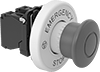
Emergency Stop Switches