About Hazardous Location Environmental Ratings
More
Choosing an Electrical Switch
More
Miniature Panel-Mount Push-Button Switches

Sized for 4 mm or 6 mm panel cutouts, these switches are often used with circuit boards to control electronics. They actuate with a quick push. Choose switches based on their actuator color for an easy way to tell them apart.
![]() For technical drawings and 3-D models, click on a part number.
For technical drawings and 3-D models, click on a part number.
| No. of Circuits Controlled | Switch Starting Position | Switch Action | No. of Terminals | Industry Designation | Actuator Color | Switching Current @ Voltage | Max. Voltage | Dia. | Dp. Behind Panel | Each | |
Metal Base with Solder Connection | |||||||||||
|---|---|---|---|---|---|---|---|---|---|---|---|
For 6 mm Panel Cutout Dia. | |||||||||||
| 2 | 2 Off (Normally Open) or 2 On (Normally Closed) | Springs Back (Momentary) | 6 | DPDT | White | 1 A @ 120 V AC/ 28 V DC | 28V DC 120V AC | 0.12" | 0.72" | 0000000 | 000000 |
Metal Base with Solder Connection and Push Reset | |||||||||||
For 6 mm Panel Cutout Dia. | |||||||||||
| 2 | 2 Off (Normally Open) or 2 On (Normally Closed) | Stays Switched (Maintained) | 6 | DPDT | Black | 6 A @ 120 V AC/ 28 V DC | 28V DC 120V AC | 0.38" | 0.76" | 00000000 | 00000 |
Wet-Location Toggle Switches

A rubber seal protects these switches from splashing water.
NEMA 4, 13, and IP68 rated switches are protected against oil/coolant spraying, washdowns, and temporary submersion. IP67 rated switches are protected against temporary submersion.
Switches with maintained/momentary switch action stay switched from one side and spring back from the other side.
Switches with an on-on or on-(on) position designation alternate power between sets of terminals.
![]() For technical drawings and 3-D models, click on a part number.
For technical drawings and 3-D models, click on a part number.
Wire Leads | |||||||||||||
|---|---|---|---|---|---|---|---|---|---|---|---|---|---|
| No. of Circuits Controlled | Switch Starting Position | Switch Action | No. of Terminals | Industry Designation | Position Designation | Switching Current @ Voltage | Max. Voltage | No. of | Lg. | Mounting Hardware Included | Choose a Wire Connection Type | Each | |
2 Position with Rounded Toggle—NEMA 4, NEMA 13, IP68 | |||||||||||||
For 1/2" Panel Cutout Dia. | |||||||||||||
| 2 | 2 Off (Normally Open) or 2 On (Normally Closed) | Stays Switched (Maintained) | 6 | DPDT | On-On | 15 A @ 125 V AC/28 V DC | 28V DC 277V AC | __ | __ | Yes | 0000000 | 000000 | |
2 Position with Rounded Toggle—IP67 | |||||||||||||
For 1/2" Panel Cutout Dia. | |||||||||||||
| 2 | 2 Off (Normally Open) or 2 On (Normally Closed) | Stays Switched (Maintained) | 6 | DPDT | On-On | 20 A @ 125 V AC/28 V DC | 30V DC 250V AC | __ | __ | Yes | 0000000 | 00000 | |
| 2 | 2 Off (Normally Open) or 2 On (Normally Closed) | Stays Switched (Maintained) | 6 | DPDT | On-On | 20 A @ 125 V AC, 20 A @ 28 V DC | 30V DC 250V AC | 6 | 12" | Yes | Wire Leads | 00000000 | 00000 |
| 2 | 2 Off (Normally Open) or 2 On (Normally Closed) | Stays Switched (Maintained)/Springs Back (Momentary) | 6 | DPDT | On-(On) | 15 A @ 125 V AC, 20 A @ 28 V DC | 30V DC 250V AC | __ | __ | Yes | 0000000 | 00000 | |
3 Position with Rounded Toggle—NEMA 4, NEMA 13, IP68 | |||||||||||||
For 1/2" Panel Cutout Dia. | |||||||||||||
| 2 | 2 Off (Normally Open) or 2 On (Normally Closed) | Stays Switched (Maintained) | 6 | DPDT | On-Off-On | 15 A @ 125 V AC/28 V DC | 28V DC 277V AC | __ | __ | Yes | 0000000 | 00000 | |
| 2 | 2 Off (Normally Open) or 2 On (Normally Closed) | Springs Back (Momentary) | 6 | DPDT | (On)-Off-(On) | 10 A @ 125 V AC/28 V DC | 28V DC 277V AC | __ | __ | Yes | 0000000 | 00000 | |
3 Position with Rounded Toggle—IP67 | |||||||||||||
For 1/2" Panel Cutout Dia. | |||||||||||||
| 2 | 2 Off (Normally Open) or 2 On (Normally Closed) | Stays Switched (Maintained) | 6 | DPDT | On-Off-On | 20 A @ 125 V AC/28 V DC | 30V DC 250V AC | __ | __ | Yes | 0000000 | 00000 | |
| 2 | 2 Off (Normally Open) or 2 On (Normally Closed) | Stays Switched (Maintained) | 6 | DPDT | On-Off-On | 20 A @ 125 V AC, 20 A @ 28 V DC | 30V DC 250V AC | 6 | 12" | Yes | Wire Leads | 00000000 | 00000 |
| 2 | 2 Off (Normally Open) or 2 On (Normally Closed) | Springs Back (Momentary) | 6 | DPDT | (On)-Off-(On) | 15 A @ 125 V AC, 20 A @ 28 V DC | 30V DC 250V AC | __ | __ | Yes | 0000000 | 00000 | |
| 2 | 2 Off (Normally Open) or 2 On (Normally Closed) | Springs Back (Momentary) | 6 | DPDT | (On)-Off-(On) | 15 A @ 125 V AC, 20 A @ 28 V DC | 30V DC 250V AC | 6 | 12" | Yes | Wire Leads | 00000000 | 00000 |
| 2 | 2 Off (Normally Open) or 2 On (Normally Closed) | Springs Back (Momentary) | 6 | DPDT | (On)-Off-On | 15 A @ 125 V AC, 20 A @ 28 V DC | 30V DC 250V AC | __ | __ | Yes | 0000000 | 00000 | |
| 2 | 2 Off (Normally Open) or 2 On (Normally Closed) | Springs Back (Momentary) | 6 | DPDT | (On)-Off-On | 15 A @ 125 V AC, 20 A @ 28 V DC | 30V DC 250V AC | 6 | 12" | Yes | Wire Leads | 00000000 | 00000 |
Mil. Spec. Washdown Toggle Switches

These switches meet MIL-S-3950. A rubber seal protects them from washdowns.
Switches with an on-on, on-on-on, or (on)-on-on position designation alternate power between sets of terminals.
![]() For technical drawings and 3-D models, click on a part number.
For technical drawings and 3-D models, click on a part number.
| No. of Circuits Controlled | Switch Starting Position | Switch Action | No. of Terminals | Industry Designation | Position Designation | Switching Current @ Voltage | Max. Voltage | Dp. Behind Panel | Mounting Hardware Included | Wire Connection Type | Each | |
2 Position | ||||||||||||
|---|---|---|---|---|---|---|---|---|---|---|---|---|
For 1/2" Panel Cutout Dia. | ||||||||||||
| 2 | 2 Off (Normally Open) or 2 On (Normally Closed) | Stays Switched (Maintained) | 6 | DPDT | On-On | 15 A @ 125 V AC/28 V DC | 28V DC 125V AC | 1.35" | Yes | Screw Terminals | 00000000 | 000000 |
| 2 | 2 Off (Normally Open) or 2 On (Normally Closed) | Springs Back (Momentary) | 6 | DPDT | On-(On) | 8 A @ 125 V AC, 10 A @ 28 V DC | 28V DC 125V AC | 1.35" | Yes | Screw Terminals | 00000000 | 00000 |
3 Position | ||||||||||||
For 1/2" Panel Cutout Dia. | ||||||||||||
| 2 | 2 Off (Normally Open) or 2 On (Normally Closed) | Stays Switched (Maintained) | 6 | DPDT | On-Off-On | 15 A @ 125 V AC/28 V DC | 28V DC 125V AC | 1.35" | Yes | Screw Terminals | 00000000 | 00000 |
| 2 | 2 Off (Normally Open) or 2 On (Normally Closed) | Stays Switched (Maintained) | 6 | DPDT | On-On-On | 15 A @ 125 V AC/28 V DC | 28V DC 125V AC | 1.35" | Yes | Screw Terminals | 00000000 | 00000 |
| 2 | 2 Off (Normally Open) or 2 On (Normally Closed) | Springs Back (Momentary) | 6 | DPDT | (On)-Off-(On) | 8 A @ 125 V AC, 10 A @ 28 V DC | 28V DC 125V AC | 1.35" | Yes | Screw Terminals | 00000000 | 00000 |
| 2 | 2 Off (Normally Open) or 2 On (Normally Closed) | Springs Back (Momentary) | 6 | DPDT | (On)-Off-On | 8 A @ 125 V AC, 10 A @ 28 V DC | 28V DC 125V AC | 1.35" | Yes | Screw Terminals | 00000000 | 00000 |
| 2 | 2 Off (Normally Open) or 2 On (Normally Closed) | Springs Back (Momentary) | 6 | DPDT | (On)-On-(On) | 8 A @ 125 V AC, 10 A @ 28 V DC | 28V DC 125V AC | 1.35" | Yes | Screw Terminals | 00000000 | 00000 |
| 2 | 2 Off (Normally Open) or 2 On (Normally Closed) | Springs Back (Momentary) | 6 | DPDT | (On)-On-On | 8 A @ 125 V AC, 10 A @ 28 V DC | 28V DC 125V AC | 1.35" | Yes | Screw Terminals | 00000000 | 00000 |
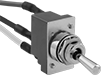
Toggle Switches

Switches with maintained/momentary switch action stay switched from one side and spring back from the other side.
Switches with an on-on or on-(on) position designation alternate power between sets of terminals.
To view switch wiring diagrams, select a part number and click Product Detail.
![]() For technical drawings and 3-D models, click on a part number.
For technical drawings and 3-D models, click on a part number.
| No. of Circuits Controlled | Switch Starting Position | Switch Action | No. of Terminals | Industry Designation | Position Designation | Switching Current @ Voltage | Max. Voltage | For Max. Panel Thick. | Mounting Hardware Included | Choose a Wire Connection Type | Each | |
2 Position with Rounded Toggle | ||||||||||||
|---|---|---|---|---|---|---|---|---|---|---|---|---|
For 1/2" Panel Cutout Dia. | ||||||||||||
| 2 | 2 Off (Normally Open) or 2 On (Normally Closed) | Stays Switched (Maintained) | 6 | DPDT | On-On | 6 A @ 125 V AC/28 V DC | 28V DC 250V AC | 0.13" | Yes | 00000000 | 000000 | |
| 2 | 2 Off (Normally Open) or 2 On (Normally Closed) | Stays Switched (Maintained) | 6 | DPDT | On-On | 15 A @ 125 V AC/28 V DC | 28V DC 250V AC | 0.13" | Yes | 00000000 | 00000 | |
| 2 | 2 Off (Normally Open) or 2 On (Normally Closed) | Stays Switched (Maintained)/Springs Back (Momentary) | 6 | DPDT | On-(On) | 15 A @ 125 V AC/28 V DC | 28V DC 250V AC | 0.13" | Yes | 0000000 | 00000 | |
| No. of Circuits Controlled | Switch Starting Position | Switch Action | No. of Terminals | Industry Designation | Position Designation | Switching Current @ Voltage | Max. Voltage | For Max. Panel Thick. | Mounting Hardware Included | Choose a Wire Connection Type | Each | |
3 Position with Rounded Toggle | ||||||||||||
|---|---|---|---|---|---|---|---|---|---|---|---|---|
For 1/2" Panel Cutout Dia. | ||||||||||||
| 2 | 2 Off (Normally Open) or 2 On (Normally Closed) | Stays Switched (Maintained) | 6 | DPDT | On-Off-On | 6 A @ 125 V AC/28 V DC | 28V DC 250V AC | 0.13" | Yes | 00000000 | 000000 | |
| 2 | 2 Off (Normally Open) or 2 On (Normally Closed) | Stays Switched (Maintained) | 6 | DPDT | On-Off-On | 15 A @ 125 V AC/28 V DC | 28V DC 250V AC | 0.13" | Yes | 00000000 | 00000 | |
| 2 | 2 Off (Normally Open) or 2 On (Normally Closed) | Springs Back (Momentary) | 6 | DPDT | (On)-Off-(On) | 15 A @ 125 V AC/28 V DC | 28V DC 250V AC | 0.13" | Yes | 00000000 | 00000 | |
Pull-to-Unlock Toggle Switches

Prevent accidental actuation—these toggle switches must be pulled out before they can switch a circuit.
Ball end toggle switches are rated NEMA 4, 13, and IP68 for protection against washdowns, oil/coolant spraying, and temporary submersion.
Switches with an on-on position designation alternate power between sets of terminals.
![]() For technical drawings and 3-D models, click on a part number.
For technical drawings and 3-D models, click on a part number.
| No. of Circuits Controlled | Switch Starting Position | Switch Action | No. of Terminals | Industry Designation | Position Designation | Switching Current @ Voltage | Max. Voltage | Mounting Hardware Included | Mounting Thread Size | Wire Connection Type | Environmental Rating | Each | |
2 Position | |||||||||||||
|---|---|---|---|---|---|---|---|---|---|---|---|---|---|
For 1/2" Panel Cutout Dia. | |||||||||||||
| 2 | 2 Off (Normally Open) or 2 On (Normally Closed) | Stays Switched (Maintained) | 6 | DPDT | On-On | 15 A @ 125 V AC/28 V DC | 28V DC 277V AC | Yes | 15/32"-32 | Screw Terminals | NEMA 4, NEMA 13, IP68 | 0000000 | 000000 |
Miniature Toggle Switches

Maximize the space in a panel—these switches are half the size of most toggle switches.
Switches with an on-on or on-(on) position designation alternate power between sets of terminals.
![]() For technical drawings and 3-D models, click on a part number.
For technical drawings and 3-D models, click on a part number.
| No. of Circuits Controlled | Switch Starting Position | Switch Action | No. of Terminals | Industry Designation | Position Designation | Switching Current @ Voltage | Max. Voltage | Dp. Behind Panel | Mounting Hardware Included | Choose a Wire Connection Type | Each | |
2 Position with Rounded Toggle | ||||||||||||
|---|---|---|---|---|---|---|---|---|---|---|---|---|
For 1/4" Panel Cutout Dia. | ||||||||||||
| 2 | 2 Off (Normally Open) or 2 On (Normally Closed) | Stays Switched (Maintained) | 6 | DPDT | On-On | 6 A @ 125 V AC, 4 A @ 30 V DC | 30V DC 250V AC | __ | Yes | 0000000 | 000000 | |
| 2 | 2 Off (Normally Open) or 2 On (Normally Closed) | Springs Back (Momentary) | 6 | DPDT | On-(On) | 6 A @ 125 V AC, 4 A @ 30 V DC | 30V DC 250V AC | 0.62" | Yes | Tab Terminals | 0000000 | 00000 |
3 Position with Rounded Toggle | ||||||||||||
For 1/4" Panel Cutout Dia. | ||||||||||||
| 2 | 2 Off (Normally Open) or 2 On (Normally Closed) | Stays Switched (Maintained) | 6 | DPDT | On-Off-On | 6 A @ 125 V AC, 4 A @ 30 V DC | 30V DC 250V AC | __ | Yes | 0000000 | 00000 | |
| 2 | 2 Off (Normally Open) or 2 On (Normally Closed) | Springs Back (Momentary) | 6 | DPDT | (On)-Off-(On) | 6 A @ 125 V AC, 4 A @ 30 V DC | 30V DC 250V AC | __ | Yes | 0000000 | 00000 | |
DIN-Rail Mount Miniature Toggle Switches
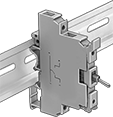
Built into a terminal block, these switches mount to DIN rail. They can be mounted side-by side.
Switches with an on-on or on-(on) position designation alternate power between sets of terminals.
![]() For technical drawings and 3-D models, click on a part number.
For technical drawings and 3-D models, click on a part number.
| No. of Circuits Controlled | Switch Starting Position | Switch Action | No. of Terminals | Industry Designation | Position Designation | Switching Current @ Voltage | Max. Voltage | For DIN Rail Ht., mm | Wire Connection Type | Each | |
2 Position | |||||||||||
|---|---|---|---|---|---|---|---|---|---|---|---|
| 2 | 2 Off (Normally Open) or 2 On (Normally Closed) | Stays Switched (Maintained) | 6 | DPDT | On-On | 5 A @ 120 V AC/28 V DC | 28V DC 250V AC | 35 | Screw Terminals | 00000000 | 0000000 |
High-Current Toggle Switches

Able to withstand high currents, these switches are often used with motors and pumps.
Switches with an on-on position designation alternate power between sets of terminals.
![]() For technical drawings and 3-D models, click on a part number.
For technical drawings and 3-D models, click on a part number.
| No. of Circuits Controlled | Switch Starting Position | Switch Action | No. of Terminals | Industry Designation | Position Designation | Switching Current @ Voltage | Max. Voltage | Dp. Behind Panel | Mounting Hardware Included | Each | |
2 Position with Screw Terminals | |||||||||||
|---|---|---|---|---|---|---|---|---|---|---|---|
For 1/2" Panel Cutout Dia. | |||||||||||
| 2 | 2 Off (Normally Open) or 2 On (Normally Closed) | Stays Switched (Maintained) | 6 | DPDT | On-On | 30 A @ 125 V AC/30 V DC | 30V DC 250V AC | 1.34" | Yes | 0000000 | 000000 |
3 Position with Screw Terminals | |||||||||||
For 1/2" Panel Cutout Dia. | |||||||||||
| 2 | 2 Off (Normally Open) or 2 On (Normally Closed) | Stays Switched (Maintained) | 6 | DPDT | On-Off-On | 30 A @ 125 V AC/30 V DC | 30V DC 250V AC | 1.34" | Yes | 0000000 | 00000 |
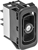
Design-Your-Own Rocker Switches
Choose from a variety of messages and colored lenses to combine a rocker with a base for a complete switch.
Bases with an on-on position designation alternate power between sets of terminals.
Note: Illuminated switches include a bulb. If wiring the switch and the bulb to the same circuit, the circuit voltage must not exceed bulb voltage.
![]() For technical drawings and 3-D models, click on a part number.
For technical drawings and 3-D models, click on a part number.
| No. of Positions | No. of Circuits Controlled | Switch Starting Position | Switch Action | No. of Terminals | Industry Designation | Position Designation | Color | Switching Current @ Voltage | Max. Voltage | Quick-Disconnect Tab Wd. | Each | |
| 2 | 2 | 2 Off (Normally Open) or 2 On (Normally Closed) | Stays Switched (Maintained) | 6 | DPDT | On-On | Black | 15 A @ 125 V AC, 15 A @ 28 V DC | 30V DC 250V AC | 0.25" | 0000000 | 000000 |
| 3 | 2 | 2 Off (Normally Open) or 2 On (Normally Closed) | Springs Back (Momentary) | 6 | DPDT | (On)-Off-(On) | Black | 15 A @ 125 V AC, 15 A @ 28 V DC | 30V DC 250V AC | 0.25" | 0000000 | 00000 |
| No. of Positions | Position Illuminated | No. of Circuits Controlled | Switch Starting Position | Switch Action | No. of Terminals | Industry Designation | Position Designation | Color | Switching Current @ Voltage | Max. Voltage | Bulb Voltage | Quick-Disconnect Tab Wd. | Each | |
| 2 | Top/Bottom | 2 | 2 Off (Normally Open) or 2 On (Normally Closed) | Stays Switched (Maintained) | 10 | DPDT | On-On | Black | 15 A @ 125 V AC, 15 A @ 28 V DC | 30V DC 250V AC | 14V DC | 0.25" | 0000000 | 000000 |
| 3 | Top/Bottom | 2 | 2 Off (Normally Open) or 2 On (Normally Closed) | Stays Switched (Maintained) | 10 | DPDT | On-Off-On | Black | 15 A @ 125 V AC, 15 A @ 28 V DC | 30V DC 250V AC | 14V DC | 0.25" | 0000000 | 00000 |
| 3 | Top/Bottom | 2 | 2 Off (Normally Open) or 2 On (Normally Closed) | Springs Back (Momentary) | 10 | DPDT | (On)-Off-(On) | Black | 15 A @ 125 V AC, 15 A @ 28 V DC | 30V DC 250V AC | 14V DC | 0.25" | 0000000 | 00000 |
Submersible High-Starting-Current Rocker Switches

Rated IP67 for protection from dust and temporary submersion. Also known as high-inrush current switches, these switches can handle starting currents up to 10 times greater than their current rating, such as when a motor starts. They're often used with amplifiers, power supplies, and other high-starting-current devices. Easy to press, these switches have a wide, flat actuation area. Color-code your switches so that operators can identify their function at a glance.
![]() For technical drawings and 3-D models, click on a part number.
For technical drawings and 3-D models, click on a part number.
| No. of Circuits Controlled | Switch Starting Position | Switch Action | No. of Terminals | Industry Designation | Position Designation | Message (Location) | Switching Current @ Voltage | Max. Voltage | Quick-Disconnect Tab Wd. | Choose a Color | Each | |
2 Position with Quick-Disconnect Terminals | ||||||||||||
|---|---|---|---|---|---|---|---|---|---|---|---|---|
For 1" Ht. × 19/32" Wd. Panel Cutout | ||||||||||||
| 2 | 2 Off (Normally Open) or 2 On (Normally Closed) | Stays Switched (Maintained) | 6 | DPDT | On-On | Blank (Top), Blank (Bottom) | 10 A @ 125 V AC, 10 A @ 30 V DC | 30V DC 250V AC | 0.11" | 00000000 | 000000 | |
For 1 7/32" Ht. × 13/16" Wd. Panel Cutout | ||||||||||||
| 2 | 2 Off (Normally Open) or 2 On (Normally Closed) | Stays Switched (Maintained) | 6 | DPDT | On-On | Blank (Top), Blank (Bottom) | 16 A @ 125 V AC | 250V AC | 0.187" | 00000000 | 00000 | |
High-Current Rocker Switches
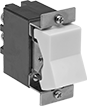
Able to withstand high currents, these switches are often used with motors and pumps.
Switches with an on-on position designation alternate power between sets of terminals.
![]() For technical drawings and 3-D models, click on a part number.
For technical drawings and 3-D models, click on a part number.
| No. of Circuits Controlled | Switch Starting Position | Switch Action | No. of Terminals | Industry Designation | Position Designation | Color | Switching Current @ Voltage | Max. Voltage | Mounting Fasteners Included | Each | |
2 Position with Screw Terminals | |||||||||||
|---|---|---|---|---|---|---|---|---|---|---|---|
For 1 7/16" Ht.×15/16" Wd. Panel Cutout | |||||||||||
| 2 | 2 Off (Normally Open) or 2 On (Normally Closed) | Stays Switched (Maintained) | 6 | DPDT | On-On | White | 30 A @ 125 V AC | 250V AC | Yes | 0000000 | 000000 |
3 Position with Screw Terminals | |||||||||||
For 1 7/16" Ht.×15/16" Wd. Panel Cutout | |||||||||||
| 2 | 2 Off (Normally Open) or 2 On (Normally Closed) | Stays Switched (Maintained) | 6 | DPDT | On-Off-On | White | 30 A @ 125 V AC | 250V AC | Yes | 0000000 | 00000 |
| 2 | 2 Off (Normally Open) or 2 On (Normally Closed) | Stays Switched (Maintained) | 6 | DPDT | On-Off-On | White | 30 A @ 30 V DC | 125V DC | Yes | 0000000 | 00000 |
High-Starting-Current Rocker Switches

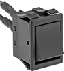
Also known as high-inrush current switches, these switches can handle starting currents up to 10 times greater than their current rating, such as when a motor starts. They're often used with amplifiers, power supplies, and other high-starting-current devices.
Switches with an on-on position designation alternate power between sets of terminals.
![]() For technical drawings and 3-D models, click on a part number.
For technical drawings and 3-D models, click on a part number.
Wire Leads | |||||||||||||
|---|---|---|---|---|---|---|---|---|---|---|---|---|---|
| No. of Circuits Controlled | Switch Starting Position | Switch Action | No. of Terminals | Industry Designation | Position Designation | Message (Location) | Switching Current @ Voltage | Max. Voltage | No. of | Lg. | Choose a Color | Each | |
2 Position with Tab Terminals | |||||||||||||
For 1 3/16"×13/16" Wd. Panel Cutout | |||||||||||||
| 2 | 2 Off (Normally Open) or 2 On (Normally Closed) | Stays Switched (Maintained) | 6 | DPDT | On-On | Blank (Top), Blank (Bottom) | 16 A @ 125 V AC, 5 A @ 30 V DC | 72V DC 250V AC | __ | __ | 0000000 | 000000 | |
2 Position with Wire Leads | |||||||||||||
For 1 3/16"×13/16" Wd. Panel Cutout | |||||||||||||
| 2 | 2 Off (Normally Open) or 2 On (Normally Closed) | Stays Switched (Maintained) | 6 | DPDT | On-On | Blank (Top), Blank (Bottom) | 16 A @ 120 V AC, 5 A @ 24 V DC | 72V DC 250V AC | 6 | 12" | Black | 0000000 | 00000 |
Rocker Switches

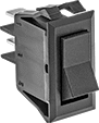
The wide surface of these switches makes them easy to press on and off, even if your hands are full and you need to use an elbow. They’re often used as power switches on electronic devices and control panels.
Switches for a 13/16” dia. panel cutout are round, so you can use a drill bit or knockout to install them instead of cutting a rectangular hole.
Switches with an on-on position designation alternate power between sets of terminals.
![]() For technical drawings and 3-D models, click on a part number.
For technical drawings and 3-D models, click on a part number.
| No. of Circuits Controlled | Switch Starting Position | Switch Action | No. of Terminals | Industry Designation | Position Designation | Switching Current @ Voltage | Max. Voltage | Quick-Disconnect Tab Wd. | Color | Each | ||
2 Position with Quick-Disconnect Terminals | ||||||||||||
|---|---|---|---|---|---|---|---|---|---|---|---|---|
For 13/16" Dia. Panel Cutout | ||||||||||||
| B | 2 | 2 Off (Normally Open) or 2 On (Normally Closed) | Stays Switched (Maintained) | 6 | DPDT | On-On | 16 A @ 125 V AC, 10 A @ 250 V AC | 250V AC | 0.189" | Black | 00000000 | 00000 |
For 1 3/16" Ht.×7/8" Wd. Panel Cutout | ||||||||||||
| C | 2 | 2 Off (Normally Open) or 2 On (Normally Closed) | Stays Switched (Maintained) | 6 | DPDT | On-On | 16 A @ 125 V AC | 250V AC | 0.25" | Black | 0000000 | 0000 |
| C | 2 | 2 Off (Normally Open) or 2 On (Normally Closed) | Stays Switched (Maintained) | 6 | DPDT | On-On | 20 A @ 125 V AC, 16 A @ 250 V AC | 250V AC | 0.25" | Black | 00000000 | 0000 |
3 Position with Quick-Disconnect Terminals | ||||||||||||
For 13/16" Dia. Panel Cutout | ||||||||||||
| B | 2 | 2 Off (Normally Open) or 2 On (Normally Closed) | Stays Switched (Maintained) | 6 | DPDT | On-Off-On | 16 A @ 125 V AC, 10 A @ 250 V AC | 250V AC | 0.189" | Black | 00000000 | 0000 |
For 0.83" Ht.×1.45" Wd. Panel Cutout | ||||||||||||
| C | 2 | 2 Off (Normally Open) or 2 On (Normally Closed) | Stays Switched (Maintained) | 6 | DPDT | On-Off-On | 15 A @ 125 V AC, 10 A @ 250 V AC | 250V AC | 0.25" | Black | 00000000 | 00000 |
For 1 3/16" Ht.×7/8" Wd. Panel Cutout | ||||||||||||
| C | 2 | 2 Off (Normally Open) or 2 On (Normally Closed) | Stays Switched (Maintained) | 6 | DPDT | On-Off-On | 15 A @ 125 V AC, 10 A @ 250 V AC | 250V AC | 0.25" | Black | 00000000 | 0000 |
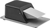
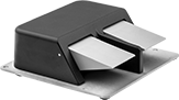
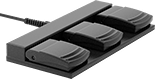
Foot Switches
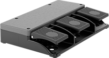
Keep your hands free for other tasks by triggering switches with your foot.
Back-pivot switches actuate with a tap of the toe. Optional guards prevent accidental switch actuation.
Switches | ||||||||||||||
|---|---|---|---|---|---|---|---|---|---|---|---|---|---|---|
Mounting | Optional Guards | |||||||||||||
| No. of Circuits Controlled | Switch Starting Position | Switch Action | Industry Designation | Switching Current @ Voltage | Housing Material | Wire Connection Type | No. of Terminals | Fasteners Included | No. of Holes | Hole Dia. | Each | Each | ||
1 Speed | ||||||||||||||
Back Pivot with 1 Pedal | ||||||||||||||
| 2 | 2 Off (Normally Open) or 2 On (Normally Closed) | Springs Back (Momentary) | DPDT | 15 A @ 125 V AC, 10 A @ 250 V AC, 3 A @ 3 V DC | Iron | Quick-Disconnect Terminals | 6 | No | 2 | 0.22" | 000000 | 000000 | 000000 | 000000 |
| 2 | 2 Off (Normally Open) or 2 On (Normally Closed) | Stays Switched (Maintained) | DPDT | 10 A @ 125 V AC/250 V AC, 3 A @ 28 V DC | Iron | Tab Terminals | 6 | No | 2 | 0.22" | 000000 | 000000 | 000000 | 00000 |
Back Pivot with 3 Pedals | ||||||||||||||
| 6 | 2 Off (Normally Open) or 2 On (Normally Closed) | Springs Back (Momentary) | DPDT | 3 A @ 240 V AC | Aluminum | Screw Terminals | 18 | __ | __ | __ | 0000000 | 00000000 | 000000 | 00 |
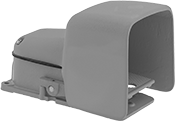
Hazardous Location Foot Switches
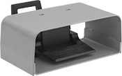
These switches are rated for environments where hazardous material is present. Press the pedal with your foot for hands-free operation. They have an oversized guard that accommodates bulky footwear.
Hazardous location environmental ratings indicate whether manufacturers have included safety features in products to facilitate their safe use in a hazardous environment. Before selecting a product for a hazardous location, ensure it is rated for your environment. See About Hazardous Location Environmental Ratings.
Mounting | ||||||||||
|---|---|---|---|---|---|---|---|---|---|---|
| No. of Circuits Controlled | Switch Starting Position | Switch Action | Industry Designation | Switching Current @ Voltage | Fasteners Included | No. of Holes | Hole Dia. | Environmental Rating | Each | |
1 Speed with Screw Terminals | ||||||||||
Aluminum Housing with 1 Pedal, Oversized Guard, and Back Pivot | ||||||||||
| 2 | 2 Off (Normally Open) or 2 On (Normally Closed) | Springs Back (Momentary) | DPDT | 20 A @ 125 V AC/250 V AC | No | 6 | 0.28" | NEC Class I Divisions 1, 2 Group D NEC Class II Divisions 1, 2 Groups F, G NEC Zone 1 Group IIA IP41 NEMA 2 NEMA 7 NEMA 9 | 0000000 | 0000000 |
Wet-Location Foot Switches
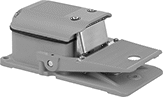
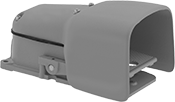
Operate these switches hands-free when working in damp or humid environments. They’re IP and NEMA rated, so they won’t corrode when exposed to water, oil, or coolant spray.
Switches without a guard are unobstructed and let you press them from multiple angles. Switches with a guard shield the pedal so you don't accidentally step on it and activate the switch. Switches with an oversized guard fit bulky shoes and toe guards.
Switches with a safety lever lock the pedal in place to prevent accidental activation. Fully insert your foot to release the safety lever. If the lever isn't released, the pedal won't depress.
Add an optional oversized guard to switches with or without a standard guard to shield the pedal from getting pressed by accident and to accommodate bulky shoes. Or, replace an existing oversized guard.
Mounting | |||||||||||||
|---|---|---|---|---|---|---|---|---|---|---|---|---|---|
| No. of Speeds | No. of Circuits Controlled | Switch Starting Position | Switch Action | Industry Designation | Switching Current @ Voltage | Wire Connection Type | No. of Terminals | Conduit Trade Size | Fasteners Included | No. of Holes | Hole Dia. | Each | |
Iron Housing | |||||||||||||
IP56, NEMA 4, NEMA 13 | |||||||||||||
| 1 | 2 | 2 Off (Normally Open) or 2 On (Normally Closed) | Springs Back (Momentary) | DPDT | 20 A @ 125 V AC/250 V AC, 0.5 A @ 125 V DC, 0.25 A @ 250 V DC | Screw Terminals | 6 | 3/4 | No | 3 | 0.31" | 00000000 | 0000000 |
Iron Housing with Aluminum Guard | |||||||||||||
IP56, NEMA 4, NEMA 13 | |||||||||||||
| 1 | 2 | 2 Off (Normally Open) or 2 On (Normally Closed) | Springs Back (Momentary) | DPDT | 20 A @ 125 V AC/250 V AC, 0.5 A @ 125 V DC, 0.25 A @ 250 V DC | Screw Terminals | 6 | 3/4 | No | 3 | 0.31" | 0000000 | 000000 |
Iron Housing with Oversized Aluminum Guard | |||||||||||||
IP56, NEMA 4, NEMA 13 | |||||||||||||
| 1 | 2 | 2 Off (Normally Open) or 2 On (Normally Closed) | Springs Back (Momentary) | DPDT | 20 A @ 125 V AC/250 V AC, 0.5 A @ 125 V DC, 0.25 A @ 250 V DC | Screw Terminals | 6 | 3/4 | No | 3 | 0.31" | 0000000 | 000000 |
Iron Housing with Safety Lever and Oversized Aluminum Guard | |||||||||||||
IP56, NEMA 4, NEMA 13 | |||||||||||||
| 1 | 2 | 2 Off (Normally Open) or 2 On (Normally Closed) | Springs Back (Momentary) | DPDT | 20 A @ 125 V AC/250 V AC, 0.5 A @ 125 V DC, 0.25 A @ 250 V DC | Screw Terminals | 6 | 3/4 | No | 3 | 0.31" | 0000000 | 000000 |
| Optional Oversized Guards | 0000000 | Each | 000000 |
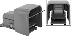
Corrosion-Resistant Washdown Foot Switches
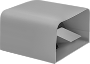
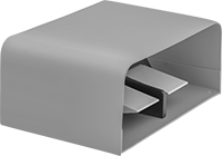
Step on these switches to actuate a process hands-free in an area with frequent washdowns. Rated NEMA 6P, 13, and IP68, they protect against corrosion, washdowns, temporary submersion, and oil/coolant spraying. Made of aluminum, they resist corrosion better than iron and steel switches.
Switches without a guard let you easily see the pedal and step on it from many angles.
Switches with a guard shield the pedal from getting accidentally pressed down.
Switches | |||||||||||||||
|---|---|---|---|---|---|---|---|---|---|---|---|---|---|---|---|
Mounting | Replacement Foot Pedals | ||||||||||||||
| No. of Circuits Controlled | Switch Starting Position | Switch Action | Industry Designation | Switching Current @ Voltage | No. of Terminals | Quick-Disconnect Tab Wd. | Conduit Trade Size | Fasteners Included | No. of Holes | Hole Dia. | Each | Each | |||
1 Speed with Quick-Disconnect Terminals | |||||||||||||||
Aluminum Housing | |||||||||||||||
| C | 2 | 2 Off (Normally Open) or 2 On (Normally Closed) | Springs Back (Momentary) | DPDT | 16 A @ 125 V AC/250 V AC | 6 | 0.187" | 1/2 | No | 4 | 0.28" | 0000000 | 0000000 | 0000000 | 00000 |
| D | 4 | 2 Off (Normally Open) or 2 On (Normally Closed) | Springs Back (Momentary) | DPDT | 16 A @ 125 V AC/250 V AC | 12 | 0.187" | 3/4 | No | 4 | 0.28" | 0000000 | 000000 | 0000000 | 0000 |
Aluminum Housing with Steel Guard | |||||||||||||||
| E | 2 | 2 Off (Normally Open) or 2 On (Normally Closed) | Springs Back (Momentary) | DPDT | 16 A @ 125 V AC/250 V AC | 6 | 0.187" | 1/2 | No | 4 | 0.28" | 0000000 | 000000 | 0000000 | 0000 |
| F | 4 | 2 Off (Normally Open) or 2 On (Normally Closed) | Springs Back (Momentary) | DPDT | 16 A @ 125 V AC/250 V AC | 12 | 0.187" | 3/4 | No | 4 | 0.28" | 0000000 | 000000 | 0000000 | 0000 |
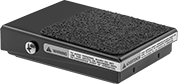
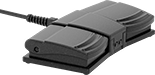
Light Duty Foot Switches
Use these switches for intermittent, light duty applications.
IP43 rated switches can be used in industrial kitchen settings or around machinery where light water spray might occur.
![]() For technical drawings and 3-D models, click on a part number.
For technical drawings and 3-D models, click on a part number.

No. of | Wire Leads | |||||||||
|---|---|---|---|---|---|---|---|---|---|---|
| Pedals | Circuits Controlled | Switch Starting Position | Switch Action | Industry Designation | Switching Current @ Voltage | No. of | Lg., ft. | Color | Each | |
Plastic Housing | ||||||||||
IP43 | ||||||||||
| 1 | 2 | 2 Off (Normally Open) or 2 On (Normally Closed) | Springs Back (Momentary) | DPDT | 5 A @ 125 V AC/250 V AC | 6 | 6 | Black | 00000000 | 0000000 |
| 1 | 2 | 2 Off (Normally Open) or 2 On (Normally Closed) | Stays Switched (Maintained) | DPDT | 5 A @ 125 V AC/250 V AC | 6 | 6 | Black | 00000000 | 000000 |
| 2 | 4 | 2 Off (Normally Open) or 2 On (Normally Closed) | Springs Back (Momentary) | DPDT | 5 A @ 125 V AC/250 V AC | 12 | 6 | Black | 00000000 | 000000 |
| 2 | 4 | 2 Off (Normally Open) or 2 On (Normally Closed) | Stays Switched (Maintained) | DPDT | 5 A @ 125 V AC/250 V AC | 12 | 6 | Black | 00000000 | 000000 |
| 3 | 6 | 2 Off (Normally Open) or 2 On (Normally Closed) | Springs Back (Momentary) | DPDT | 5 A @ 125 V AC/250 V AC | 18 | 6 | Black | 00000000 | 000000 |
| 3 | 6 | 2 Off (Normally Open) or 2 On (Normally Closed) | Stays Switched (Maintained) | DPDT | 5 A @ 125 V AC/250 V AC | 18 | 6 | Black | 00000000 | 000000 |
Slide Switches


Like turning on a flashlight, slide these switches from one side to the other.
![]() For technical drawings and 3-D models, click on a part number.
For technical drawings and 3-D models, click on a part number.
Wire Leads | Mounting | |||||||||||||
|---|---|---|---|---|---|---|---|---|---|---|---|---|---|---|
| No. of Circuits Controlled | Switch Starting Position | Switch Action | No. of Terminals | Industry Designation | Switching Current @ Voltage | Max. Voltage | Dp. Behind Panel | No. of | Lg. | Fasteners Included | No. of Holes | Hole Dia. | Each | |
2 Position with Tab Terminals | ||||||||||||||
For 7/8" Ht.×1/2" Wd. Panel Cutout | ||||||||||||||
| 2 | 2 Off (Normally Open) or 2 On (Normally Closed) | Stays Switched (Maintained) | 6 | DPDT | 6 A @ 125 V AC, 1 A @ 125 V DC | 125V DC 250V AC | 9/16" | __ | __ | No | 2 | 5/32" | 00000000 | 00000 |
2 Position with Wire Leads | ||||||||||||||
For 7/8" Ht.×1/2" Wd. Panel Cutout | ||||||||||||||
| 2 | 2 Off (Normally Open) or 2 On (Normally Closed) | Stays Switched (Maintained) | 6 | DPDT | 6 A @ 125 V AC, 1 A @ 125 V DC | 125V DC 250V AC | 9/16" | 6 | 6" | No | 2 | 5/32" | 00000000 | 00000 |
3/4" Panel-Mount Key Switches

Prevent accidental activation and limit access—these switches require a key to turn circuits on or off. All fit into a standard panel cutout.
Keyed alike switches all open with the same key.
![]() For technical drawings and 3-D models, click on a part number.
For technical drawings and 3-D models, click on a part number.
Switches | Replacement Keys | |||||||||||||
|---|---|---|---|---|---|---|---|---|---|---|---|---|---|---|
| No. of Circuits Controlled | Switch Starting Position | Switch Action | No. of Terminals | Industry Designation | Switching Current @ Voltage | Max. Voltage | Dia. | Dp. Behind Panel | No. of Keys Included | Key Removal Position | Each | Each | ||
2 Position with Metal Base | ||||||||||||||
Keyed Alike with Tab Terminals | ||||||||||||||
| 2 | 2 Off (Normally Open) or 2 On (Normally Closed) | Stays Switched (Maintained) | 6 | DPDT | 4 A @ 125 V AC/24 V DC | 28V DC 125V AC | 7/8" | 1 1/16" | 2 | Center | 0000000 | 000000 | 000000 | 00000 |
| 2 | 2 Off (Normally Open) or 2 On (Normally Closed) | Stays Switched (Maintained) | 6 | DPDT | 4 A @ 125 V AC/24 V DC | 28V DC 125V AC | 7/8" | 1 1/16" | 2 | Center, Right | 0000000 | 00000 | 000000 | 0000 |
| No. of Circuits Controlled | Switch Starting Position | Switch Action | No. of Terminals | Industry Designation | Switching Current @ Voltage | Max. Voltage | Dia. | Dp. Behind Panel | No. of Keys Included | Key Removal Position | Each | |
3 Position with Metal Base | ||||||||||||
|---|---|---|---|---|---|---|---|---|---|---|---|---|
Keyed Alike with Tab Terminals | ||||||||||||
| 2 | 2 Off (Normally Open) or 2 On (Normally Closed) | Stays Switched (Maintained) | 8 | DPDT | 4 A @ 125 V AC/24 V DC | 28V DC 125V AC | 7/8" | 1 1/16" | 2 | Center | 0000000 | 000000 |
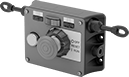
Cable-Pull Emergency Stop Switches with Restart Switch
Tug the cable to stop your line, then follow it back to the restart switch. Typically separate devices, the stop and reset controls are in one compact unit. As a secondary shutdown option, a push-button stop switch is also built in. A secondary push-button stop switch ensures you can halt equipment immediately, even when the cable is out of reach. Because they let you control circuits from a distance with a quick tug, these cable-pull stop switches are often used to turn off production lines and material handling systems. To notify your team on the floor that you’ve stopped equipment, a power indicator lights up when you pull the cable.
Use the tension indicator to confirm that cable is set up correctly. Circuits remain open until you tension the cable and hit the restart button. Cable is not included.
Two-direction switches support twice the total cable distance of one-direction switches. With pulls on each side, you can route cable in two opposite directions. These switches are often placed at the midpoint of conveyors and other long runs of equipment.
![]() For technical drawings and 3-D models, click on a part number.
For technical drawings and 3-D models, click on a part number.


Mounting | |||||||||||||||
|---|---|---|---|---|---|---|---|---|---|---|---|---|---|---|---|
| Cable Location | For Max. Cable Lg., ft. | No. of Circuits Controlled | Switch Starting Position | No. of Terminals | Industry Designation | Switching Current @ Voltage | Max. Voltage | Actuation Force, lbs. | Conduit Trade Size | Bulb Voltage | Fasteners Included | No. of Holes | Hole Dia. | Each | |
With Screw Terminals | |||||||||||||||
With Restart Button, Emergency Stop Button, Power Indicator and Tension Indicator (IP54, NEMA 1) | |||||||||||||||
| Left Side | 325 | 2 | 2 Off (Normally Open) or 2 On (Normally Closed) | 6 | DPDT | 6 A @ 120 V AC, 2.8 A @ 24 V DC | 240V AC 24V DC | 11 | 1/2 | 24V DC | No | 4 | 1/4" | 00000000 | 0000000 |
| Left Side | 325 | 2 | 2 Off (Normally Open) or 2 On (Normally Closed) | 6 | DPDT | 6 A @ 120 V AC, 2.8 A @ 24 V DC | 240V AC 24V DC | 11 | 1/2 | 120V AC | No | 4 | 1/4" | 00000000 | 00000000 |
| Right Side | 325 | 2 | 2 Off (Normally Open) or 2 On (Normally Closed) | 6 | DPDT | 6 A @ 120 V AC, 2.8 A @ 24 V DC | 240V AC 24V DC | 11 | 1/2 | 24V DC | No | 4 | 1/4" | 0000000 | 000000 |
| Right Side | 325 | 2 | 2 Off (Normally Open) or 2 On (Normally Closed) | 6 | DPDT | 6 A @ 120 V AC, 2.8 A @ 24 V DC | 240V AC 24V DC | 11 | 1/2 | 120V AC | No | 4 | 1/4" | 00000000 | 00000000 |
Mounting | ||||||||||||||
|---|---|---|---|---|---|---|---|---|---|---|---|---|---|---|
| For Max. Cable Lg., ft. | No. of Circuits Controlled | Switch Starting Position | No. of Terminals | Industry Designation | Switching Current @ Voltage | Max. Voltage | Actuation Force, lbs. | Conduit Trade Size | Bulb Voltage | Fasteners Included | No. of Holes | Hole Dia. | Each | |
With Screw Terminals | ||||||||||||||
With Restart Button, Emergency Stop Button, Power Indicator and Tension Indicator (IP54, NEMA 1) | ||||||||||||||
| 325 | 2 | 2 Off (Normally Open) or 2 On (Normally Closed) | 6 | DPDT | 6 A @ 120 V AC, 2.8 A @ 24 V DC | 240V AC 24V DC | 11 | 1/2 | 24V DC | No | 4 | 1/4" | 0000000 | 000000000 |
| 325 | 2 | 2 Off (Normally Open) or 2 On (Normally Closed) | 6 | DPDT | 6 A @ 120 V AC, 2.8 A @ 24 V DC | 240V AC 24V DC | 11 | 1/2 | 120V AC | No | 4 | 1/4" | 00000000 | 00000000 |
Cable-Pull Emergency Stop Switches
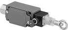
Immediately cut power by pulling a cable. These switches are often used to turn off production lines and material handling systems in an emergency. All have positive-force, snap-open contacts that open a circuit when actuated, even if a spring fails or the contacts stick. The contacts will remain open until you tension the cable and reset the switch.
Accessory kits (sold separately) simplify the installation of a new switch.
![]() For technical drawings and 3-D models, click on a part number.
For technical drawings and 3-D models, click on a part number.
Switches | ||||||||||||||||
|---|---|---|---|---|---|---|---|---|---|---|---|---|---|---|---|---|
Mounting | Accessory Kits | |||||||||||||||
| For Max. Cable Lg., ft. | No. of Circuits Controlled | Switch Starting Position | No. of Terminals | Industry Designation | Switching Current @ Voltage | Max. Voltage | Actuation Force, lbs. | Conduit Trade Size | Fasteners Included | No. of Holes | Hole Dia. | Each | Includes | Each | ||
With Screw Terminals | ||||||||||||||||
1 Direction (IP65, NEMA 4) | ||||||||||||||||
| 75 | 2 | 2 Off (Normally Open) or 2 On (Normally Closed) | 6 | DPDT | 10 A @ 120 V AC | 380V AC | 45 | 1/2 | No | 4 | 1/4" | 00000000 | 0000000 | Cable, Clamps, Tension Screws, Thimbles | 00000000 | 0000000 |
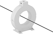
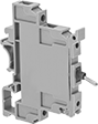
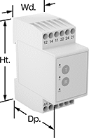
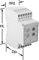
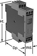
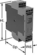
Ground-Fault Monitoring Relays
Detect and mitigate ground faults to prevent harm to equipment, circuits, and people. These relays monitor the differential between incoming and outgoing current, also known as residual current. When the balance is off, they trip and cut power to the circuit. These relays are highly sensitive, so you can trust them to de-energize faulty circuits before a minor issue becomes a major one. Rated IP20, they have recessed terminals that keep fingers and other objects from touching live circuits. Mount them on 35 mm DIN rail (also known as DIN 3 rail) for fast installation.
These relays require a current-indicating ring (sold separately) to operate. Choose a ring that is large enough for your lines to pass through. Feed the lines of the circuit through the center of the ring and connect the indicating ring output to the relay.
Relays with spring-clamp terminals connect and disconnect to wire without screws. Because they don’t have screws, there’s less of a risk that they will loosen over time, even when they’re under vibration.
Relays with IO link can be programmed, monitored, and reset remotely by connecting them to a programmable logic controller (PLC), human-machine interface (HMI), or computer. If you want to program them locally, they have a keypad.
Relays with knob adjustments have knobs right on the front where you can set your trip current.
Relays with an LED indicator show the status of your relay, so you know it is wired correctly and when it is actuated.
![]() For technical drawings and 3-D models, click on a part number.
For technical drawings and 3-D models, click on a part number.
Trip Current | ||||||||||||||
|---|---|---|---|---|---|---|---|---|---|---|---|---|---|---|
| No. of Terminals | Input Voltage | Trip Current Setting | Min. | Max. | Trip Time, sec. | Switching Current @ Voltage | Max. Switching Voltage | Adjustment Style | Ht. | Wd. | Dp. | Features | Each | |
Screw Terminals | ||||||||||||||
2 Off (Normally Open) or 2 On (Normally Closed)—DPDT | ||||||||||||||
| 12 | 24V AC, 48V AC, 120V AC, 240V AC | 0.03A | __ | __ | 0 | 5 A @ 240 V AC 5 A @ 24 V DC | 250V AC 24V DC | __ | 3.2" | 1.4" | 2.6" | LED Indicator | 00000000 | 0000000 |
| 12 | 24V AC, 48V AC, 120V AC, 240V AC | 0.3A | __ | __ | 0 | 5 A @ 240 V AC 5 A @ 24 V DC | 250V AC 24V DC | __ | 3.2" | 1.4" | 2.6" | LED Indicator | 00000000 | 000000 |
| 12 | 24V AC, 48V AC, 120V AC, 240V AC | __ | 0.3A | 30A | 0-5 | 5 A @ 240 V AC 5 A @ 24 V DC | 250V AC 24V DC | Knob | 3.2" | 1.4" | 2.8" | LED Indicator | 00000000 | 000000 |
| 12 | 24V AC, 48V AC, 120V AC, 240V AC | __ | 0.03A | 5A | 0-5 | 5 A @ 240 V AC 5 A @ 24 V DC | 250V AC 24V DC | Knob | 3.2" | 1.4" | 2.8" | LED Indicator | 00000000 | 000000 |
Screw Terminals with IO Link | ||||||||||||||
2 Off (Normally Open) or 2 On (Normally Closed)—DPDT | ||||||||||||||
| 12 | 24V DC | __ | 0.03A | 40A | 0-999 | 3 A @ 240 V AC 1 A @ 24 V DC | 400V AC 250V DC | Keypad, External Controller | 4" | 0.9" | 3.6" | Remote Reset | 00000000 | 000000 |
Spring-Clamp Terminals with IO Link | ||||||||||||||
2 Off (Normally Open) or 2 On (Normally Closed)—DPDT | ||||||||||||||
| 12 | 24V DC | __ | 0.03A | 40A | 0-999 | 3 A @ 240 V AC 1 A @ 24 V DC | 400V AC 250V DC | Keypad, External Controller | 4.1" | 0.9" | 3.6" | Remote Reset | 00000000 | 000000 |