


Wall-Mount Flat-Panel Monitor Positioning Arms
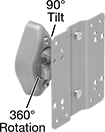
These arms have a VESA (Video Electronics Standards Association) standard mounting hole pattern to attach a monitor.
![]() For technical drawings and 3-D models, click on a part number.
For technical drawings and 3-D models, click on a part number.
Projection | Base | |||||||||||
|---|---|---|---|---|---|---|---|---|---|---|---|---|
| For Monitor Size | Min. | Max. | Max. Load Capacity, lbs. | Material | Lg. | Wd. | Mounting Fasteners Included | Attaching End Mounting Hole Pattern Compatibility | Specifications Met | Each | ||
Rotate, Tilt | ||||||||||||
| A | 10"-30" | __ | 3" | 40 | Powder-Coated Steel | 3 13/16" | 2 7/16" | Yes | VESA 75, VESA 100 | __ | 0000000 | 000000 |
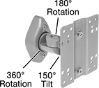
Rotate, Tilt, Side-to-Side | ||||||||||||
| B | 10"-30" | __ | 4 11/16" | 40 | Powder-Coated Steel | 3 13/16" | 2 7/16" | Yes | VESA 75, VESA 100 | __ | 0000000 | 00000 |
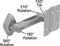
Rotate, Tilt, Side-to-Side, Up/Down, In/Out | ||||||||||||
| C | 10"-30" | 3 5/8" | 10 11/16" | 40 | Powder-Coated Steel | 3 13/16" | 2 7/16" | Yes | VESA 75, VESA 100 | __ | 0000000 | 00000 |
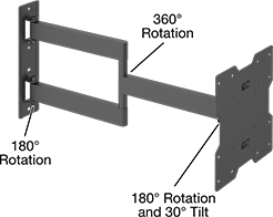
Rotate, Tilt, Side-to-Side, In/Out | ||||||||||||
| D | 13"-27" | 4 1/8" | 15 15/16" | 30 | Powder-Coated Steel | 4 5/8" | 4 5/8" | Yes | VESA 75, VESA 100 | __ | 000000 | 00000 |
| D | 17"-42" | 2 1/4" | 22 1/16" | 75 | Powder-Coated Steel | 9 5/16" | 8 3/4" | Yes | VESA 75, VESA 100, VESA 200 | __ | 000000 | 00000 |
| E | 37"-70" | 4 9/16" | 20 5/8" | 165 | Powder-Coated Steel | 31 15/16" | 8 3/4" | Yes | VESA 200, VESA 300, VESA 400, VESA 600 | __ | 000000 | 000000 |
| F | 60"-100" | 2 3/4" | 24 5/8" | 275 | Powder-Coated Steel | 37" | 15 15/16" | Yes | VESA 200, VESA 300, VESA 400, VESA 400×200, VESA 500, VESA 600, VESA 600×400, VESA 600×900, VESA 800×400, VESA 800×600 | C-UL Listed, UL Listed | 00000000 | 000000 |
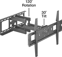
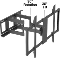
Monitor Wall Mounts
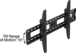
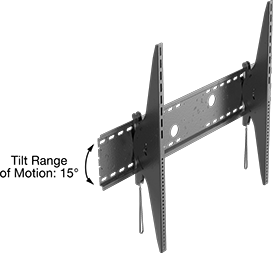
Mount flat-panel displays close to a wall. These mounts have a standard Video Electronics Standards Association (VESA) mounting hole pattern for compatibility with monitors. After installing your display, tilt these mounts up or down to create the best viewing angle. They have a low-profile design for a sleek appearance.
![]() For technical drawings and 3-D models, click on a part number.
For technical drawings and 3-D models, click on a part number.
Overall | |||||||||||
|---|---|---|---|---|---|---|---|---|---|---|---|
| For Monitor Size (Diagonal) | Tilt Range of Motion | Ht. | Wd. | Max. Load Capacity, lbs. | Material | Color | Attaching End Mounting Hole Pattern Compatibility | Mounting Fasteners Included | Specifications Met | Each | |
Up/Down | |||||||||||
| 26"-55" | 10° | 17 5/16" | 18 1/8" | 165 | Powder-Coated Steel | Black | VESA 200, VESA 200×300, VESA 200×400, VESA 300, VESA 300×200, VESA 300×400, VESA 400, VESA 400×200, VESA 400×300 | Yes | __ | 00000000 | 000000 |
| 45"-85" | 10° | 17 5/16" | 33 7/8" | 200 | Powder-Coated Steel | Black | VESA 200, VESA 200×300, VESA 200×400, VESA 300, VESA 300×200, VESA 300×400, VESA 400, VESA 400×200, VESA 400×300, VESA 500×300, VESA 500×400, VESA 600×300, VESA 600×400, VESA 800×300, VESA 800×400 | Yes | __ | 00000000 | 000000 |
| 60"-100" | 15° | 32 3/4" | 44 7/8" | 350 | Powder-Coated Steel | Black | VESA 100, VESA 100×200, VESA 1000×400, VESA 1000×500, VESA 1000×600, VESA 1000×700, VESA 1000×800, VESA 200, VESA 200×100, VESA 200×300, VESA 200×400, VESA 200×500, VESA 300, VESA 300×200, VESA 300×400, VESA 300×500, VESA 300×600, VESA 300×700, VESA 300×800, VESA 400, VESA 400×200, VESA 400×300, VESA 400×500, VESA 400×600, VESA 400×700, VESA 400×800, VESA 500, VESA 500×200, VESA 500×300, VESA 500×400, VESA 500×600, VESA 500×700, VESA 500×800, VESA 600, VESA 600×300, VESA 600×400, VESA 600×500, VESA 600×700, VESA 600×800, VESA 600×900, VESA 700, VESA 700×300, VESA 700×400, VESA 700×500, VESA 700×600, VESA 700×800, VESA 800, VESA 800×300, VESA 800×400, VESA 800×500, VESA 800×600, VESA 800×700, VESA 900×400, VESA 900×500, VESA 900×600, VESA 900×700, VESA 900×800 | Yes | UL Listed | 00000000 | 000000 |
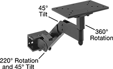
Heavy Duty Positioning Arms
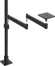
Pole Base, Pole, Pole-to-Pin Adapter, Two
Rigid Connectors, and Pivoting Mounting Plate
Heavy duty construction adds strength for higher load capacities than other positioning arms. Choose a complete arm or select a base, connectors, and plate, bracket, or tray to build a complete arm. The load capacity of an assembled arm is determined by the component with the lowest capacity.
![]() For technical drawings and 3-D models, click on a part number.
For technical drawings and 3-D models, click on a part number.
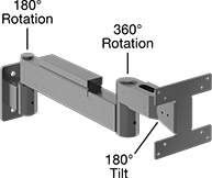
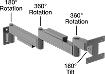
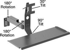
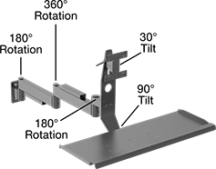
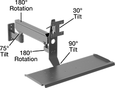
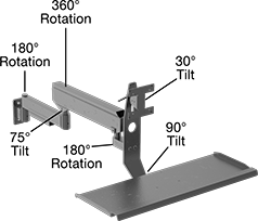
Complete arms mount to a wall with their base. Secure the object you want to position to the attaching end.
To see the product in motion, click on a part number.
Load Capacity, lbs. | Base | Attaching End | ||||||||||||||||
|---|---|---|---|---|---|---|---|---|---|---|---|---|---|---|---|---|---|---|
| Mount. Location | Max. Projection | Min. | Max. | Material | Color | Mount. Fasteners Included | Lg. | Wd. | No. of Mount. Holes | Mount. Hole Dia. | Plate Lg. | Plate Wd. | No. of Mount. Holes | Mount. Hole Dia. | Includes | Each | ||
| A | Wall | 27" | __ | 100 | Powder-Coated Steel | Black | No | 6" | 6" | 4 | 13/32" | 6" | 6" | 4 | 13/32" | Pivoting Mounting Plate, (2) Rigid Connectors, Pin Base | 000000 | 0000000 |
| A | Wall | 39" | __ | 100 | Powder-Coated Steel | Black | No | 6" | 6" | 4 | 13/32" | 6" | 6" | 4 | 13/32" | Pivoting Mounting Plate, (2) Rigid Connectors, Pin Base | 000000 | 000000 |
| B | Wall | 7" | __ | 25 | Powder-Coated Steel | Black | No | 4 1/2" | 2" | 2 | 13/32" | 4 1/2" | 4 1/2" | 8 | 3/16" | Flat-Panel Monitor Mounting Plate, Pin Base | 0000000 | 000000 |
| C | Wall | 19" | __ | 25 | Powder-Coated Steel | Black | No | 4 1/2" | 2" | 2 | 13/32" | 4 1/2" | 4 1/2" | 8 | 3/16" | Flat-Panel Monitor Mounting Plate, Rigid Connector, Cable Protector, Pin Base | 0000000 | 000000 |
| D | Wall | 31" | __ | 25 | Powder-Coated Steel | Black | No | 4 1/2" | 2" | 2 | 13/32" | 4 1/2" | 4 1/2" | 8 | 3/16" | Flat-Panel Monitor Mounting Plate, (2) Rigid Connectors, (2) Cable Protectors, Pin Base | 0000000 | 000000 |
| E | Wall | 29" | __ | 25 | Powder-Coated Steel | Black | No | 4 1/2" | 2" | 2 | 13/32" | 4 1/2" | 4 1/2" | 8 | 3/16" | Flat-Panel Monitor Mounting Plate, Keyboard Tray, Rigid Connector, Cable Protector, Pin Base | 0000000 | 000000 |
| F | Wall | 41" | __ | 25 | Powder-Coated Steel | Black | No | 4 1/2" | 2" | 2 | 13/32" | 4 1/2" | 4 1/2" | 8 | 3/16" | Flat-Panel Monitor Mounting Plate, Keyboard Tray, (2) Rigid Connectors, (2) Cable Protectors, Pin Base | 0000000 | 000000 |
| G | Wall | 36" | 4 | 21 | Powder-Coated Steel | Black | No | 6" | 2 1/2" | 3 | 13/32" | 4 1/2" | 4 1/2" | 8 | 3/16" | Flat-Panel Monitor Mounting Plate, Keyboard Tray, Counterbalancing Connector, Cable Protector, Pin Base | 0000000 | 000000 |
| H | Wall | 43" | 18 | 43 | Powder-Coated Steel | Black | No | 4 1/2" | 2" | 2 | 13/32" | 4 1/2" | 4 1/2" | 8 | 3/16" | Flat-Panel Monitor Mounting Plate, Keyboard Tray, Rigid Connector, Counterbalancing Connector, (2) Cable Protectors, Pin Base | 0000000 | 000000 |
Rail-Mount
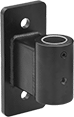
Pin Base
Pin bases are for use with rigid and counterbalancing connectors. Wall- and T-slot rail-mount pin bases do not include fasteners for T-slotted framing.
Mount. | ||||||||||||||
|---|---|---|---|---|---|---|---|---|---|---|---|---|---|---|
| Mount. Location | For Single T-Slot Rail Ht. | For Double, Quad T-Slot Rail Ht. | Lg. | Wd. | Ht. | For Pin Dia. | Max. Load Capacity, lbs. | Material | Color | Fasteners Included | No. of Holes | Hole Dia. | Each | |
| Wall | __ | __ | 1 7/8" | 6" | 6" | 7/8" | 100 | Powder-Coated Steel | Black | No | 4 | 13/32" | 0000000 | 000000 |
| Wall, T-Slot Rail | 1 1/2", 30mm, 40mm, 45mm | 3", 60mm, 80mm, 90mm | 3" | 2" | 4 1/2" | 7/8" | 50 | Powder-Coated Steel | Black | No | 2 | 13/32" | 00000000 | 00000 |
| Wall, T-Slot Rail | 1 1/2", 30mm, 40mm, 45mm | 3", 60mm, 80mm, 90mm | 7 1/8" | 2 1/2" | 6" | 7/8" | 75 | Powder-Coated Steel | Black | No | 3 | 13/32" | 00000000 | 000000 |
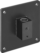
Pole bases are for use with poles for building arms with an extended reach. To mount rigid and counterbalancing connectors to poles, use a pole-to-pin adapter.
Mount. | ||||||||||||
|---|---|---|---|---|---|---|---|---|---|---|---|---|
| Mount. Location | Lg. | Wd. | Ht. | For Pole Dia. | Max. Load Capacity, lbs. | Material | Color | Fasteners Included | No. of Holes | Hole Dia. | Each | |
| Wall | 3" | 4 1/2" | 3" | 2" | 100 | Powder-Coated Aluminum | Black | No | 4 | 5/16" | 00000000 | 0000000 |
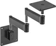
Positioning Arms
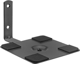
Mount the base to a wall and secure the object you want to position to the attaching end.
Pivoting arms have handles to lock joints into position.
Fixed arm includes slip-resistant plate pads that reduce vibration.
To see the product in motion, click on a part number.
![]() For technical drawings and 3-D models, click on a part number.
For technical drawings and 3-D models, click on a part number.
Base | Attaching End | |||||||||||||
|---|---|---|---|---|---|---|---|---|---|---|---|---|---|---|
| Max. Projection | Max. Load Capacity, lbs. | Material | Color | Mount. Fasteners Included | Lg. | Wd. | No. of Mount. Holes | Mount. Hole Dia. | Plate Lg. | Plate Wd. | No. of Mount. Holes | Mount. Hole Dia. | Each | |
Wall Mount | ||||||||||||||
Pivoting Arm | ||||||||||||||
| 13" | 8 | Anodized Aluminum | Black | Yes | 3" | 2" | 4 | 17/64" | 6" | 4" | 12 | 13/64" | 0000000 | 0000000 |
| 20" | 8 | Anodized Aluminum | Black | Yes | 3" | 2" | 4 | 17/64" | 6" | 4" | 12 | 13/64" | 0000000 | 000000 |
Fixed Arm | ||||||||||||||
| 8 1/2" | 12 | Powder-Coated Steel | Black | No | 4 1/2" | 1 1/4" | 2 | 3/16" | 6" | 6" | 4 | 1/4" | 0000000 | 00000 |
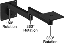
Ball-Grip Positioning Arms
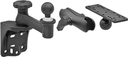
Ball-and-socket connections allow 360° positioning. Choose a complete arm or select a base, connectors, and accessories to build your own.
To ensure compatibility, select components that have the same ball diameter. Use reducing connectors (sold separately) to pair components with a 1 1/2" ball diameter to those with a 1" ball diameter.
![]() For technical drawings and 3-D models, click on a part number.
For technical drawings and 3-D models, click on a part number.
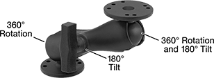
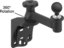
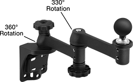
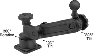
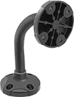
Rotating and rotating/tilting complete arms have handles to lock joints into position. Rotating/tilting complete arms mount to a bench or a wall. Secure the object you want to position to the attaching end plate.
Any-which-way complete arms bend and stay in position. They do not have a ball; affix a screw-on base (sold separately) to attach to a connector.
To see the product in motion, click on a part number.
Base | Attaching End | |||||||||||||||
|---|---|---|---|---|---|---|---|---|---|---|---|---|---|---|---|---|
| Mount. Location | Max. Projection | Ht. | Ball Dia. | Max. Load Capacity, lbs. | Material | Ball Material | Mount. Fasteners Included | Dia. | Lg. | Wd. | No. of Mount. Holes | Mount Hole Dia. | Plate Dia. | Mount. Hole Dia. | Each | |
Rotating/Tilting | ||||||||||||||||
| Bench, Wall | 7 1/4" | __ | __ | 3 | Powder-Coated Aluminum | __ | No | 2 7/16" | __ | __ | 7 | 3/16" | 2 7/16" | 3/16" | 0000000 | 000000 |
Rotating with Ball | ||||||||||||||||
| Wall | 9 1/4" | 9" | 1 1/2" | 3 | Powder-Coated Aluminum | Rubber | No | __ | 4 3/4" | 3 7/8" | 6 | 11/32" | __ | __ | 0000000 | 000000 |
Extended-Reach Rotating with Ball | ||||||||||||||||
| Wall | 15 1/4" | 11 1/4" | 1 1/2" | 3 | Powder-Coated Aluminum | Rubber | No | __ | 4 3/4" | 3 7/8" | 6 | 11/32" | __ | __ | 0000000 | 000000 |
Rotating/Tilting with Ball | ||||||||||||||||
| Bench, Wall | 14 1/2" | 14 1/2" | 1 1/2" | 3 | Powder-Coated Aluminum | Rubber | No | __ | 3 7/16" | 3 7/16" | 4 | 11/32" | __ | __ | 0000000 | 000000 |
Any-Which-Way | ||||||||||||||||
| Bench, Wall | __ | 7 3/8" | __ | 1 | Plastic | __ | No | 2 1/2" | __ | __ | 4 | 13/64" | 2 1/2" | 13/64" | 00000000 | 00000 |
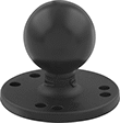
Screw-on bases have a universal AMPS (Attachment Mounting Pattern Standard) mounting hole pattern.
Round bases attach to components with four AMPS mounting holes. Round bases with seven mounting holes have an additional three-hole mounting pattern with a 1.8” bolt circle diameter.
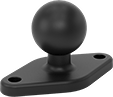
Diamond bases attach to components with two AMPS mounting holes.
Base | Mount. | |||||||||||||
|---|---|---|---|---|---|---|---|---|---|---|---|---|---|---|
| Mount. Location | Ht. | Ball Dia. | Max. Load Capacity, lbs. | Material | Mount. Hole Pattern Compatibility | Ball Material | Dia. | Lg. | Wd. | Fasteners Included | No. of Holes | Hole Dia. | Each | |
Round Base | ||||||||||||||
| Bench, Wall | 1 1/2" | 1" | 1 | Powder-Coated Aluminum | AMPS | Rubber | 2 7/16" | __ | __ | No | 7 | 7/32" | 00000000 | 000000 |
| Bench, Wall | 2 1/8" | 1 1/2" | 3 | Powder-Coated Aluminum | AMPS | Rubber | 2 1/2" | __ | __ | No | 7 | 7/32" | 0000000 | 00000 |
| Bench, Wall | 3 1/16" | 2 1/4" | 5 | Powder-Coated Aluminum | AMPS | Rubber | 2 7/16" | __ | __ | No | 4 | 7/32" | 00000000 | 00000 |
Diamond Base | ||||||||||||||
| Bench, Wall | 1 1/2" | 1" | 1 | Powder-Coated Aluminum | AMPS | Rubber | __ | 2 7/16" | 1 5/16" | No | 2 | 7/32" | 00000000 | 00000 |

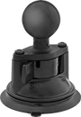
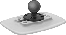
Adhesive bases attach to a surface with an adhesive pad.
Base | |||||||||
|---|---|---|---|---|---|---|---|---|---|
| Mount. Location | Ht. | Ball Dia. | Max. Load Capacity, lbs. | Material | Ball Material | Lg. | Wd. | Each | |
| Bench, Wall | 3" | 1 1/2" | 3 | Plastic | Rubber | 5 1/2" | 7 1/4" | 0000000 | 000000 |
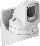
Suspension Arms for Enclosures
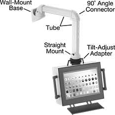 All Components Sold Separately | 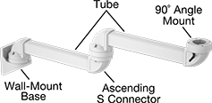 Example Configuration |
 Example Configuration |
Hang your human-machine interface and swivel it around to save floor space and comfortably access touch screens, buttons, and other operating equipment. These suspension arms have already-drilled mounting holes that match our HMI enclosures. Route wire from your HMI components to a machine through a hole that runs through the entire arm. To prevent them from swinging too far and hitting people and equipment, locking pins let you restrict how far these arms rotate. Brakes lock their position into place.
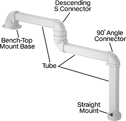
Customize a system for your application—you can create hundreds of different variations. A complete suspension arm requires at least a base, a tube, and a mount. Add components to extend your arm up to 80” from the base and expand its range of motion. Arms without a connector support up to 180 lbs. Those with a connector support up to 135 lbs., but the load it can hold decreases by 2 lbs. for every 1” over 40” from the base.
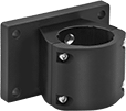
Bases mount your arm to a surface. Wall bases mount to a wall, the side of a machine, or another vertical surface.
![]() For technical drawings and 3-D models, click on a part number.
For technical drawings and 3-D models, click on a part number.
For Tube | Mounting Plate | |||||||||||
|---|---|---|---|---|---|---|---|---|---|---|---|---|
| Rotation Range of Motion | Height | Width | Height | Length | Width | Hole Diameter | Material | Color | Mounting Fasteners Included | Features | Each | |
Wall Mount | ||||||||||||
| 230° | 3 1/2" | 2 1/2" | 10" | 7 1/8" | 5 5/8" | 0.389" | Powder-Coated Aluminum | White | Yes | Cable Routing Hole, Locking Pins, Swivels | 0000000 | 0000000 |
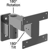
Flat-Panel Monitor Enclosures
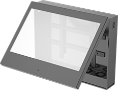
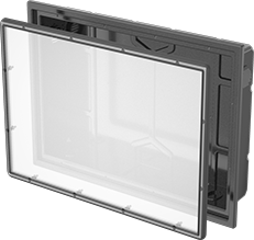
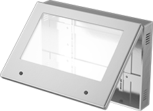
Protect monitors and televisions from environmental damage with these enclosures. The polycarbonate cover shows your display clearly and won’t shatter under impact. Enclosures fit most VESA patterns.
ABS plastic enclosures meet NEMA 12, so they seal out dust, dirt, and splashing water and oil. Mount them directly to the wall, or add an optional tilt bracket to adjust the angle of your monitor.
Rated IP55 and NEMA 4, polyethylene plastic enclosures keep your monitor dry in wet and outdoor environments. An anti-glare coating on the cover makes your display easy to see in bright light. Use a tilt bracket (sold separately) to mount these enclosures.
Stainless steel enclosures are rated IP66 and NEMA 4X for use outdoors and in corrosive environments. Mount them on your wall, or use the optional tilt bracket to hold the enclosure at a downward angle so it’s easy to see when mounted high up.
Enclosures | ||||||||||||||
|---|---|---|---|---|---|---|---|---|---|---|---|---|---|---|
Cover | Number of | Tilt Brackets | ||||||||||||
| For Maximum Monitor Size | Height | Width | Depth | Environment | Attachment Style | Closure Method | Locks | Keys Included | Color | Mounting Fasteners Included | Each | Each | ||
ABS Plastic—NEMA 12 | ||||||||||||||
| 32" | 29" | 36" | 8" | Oily | Hinged | Key Lock | 1 | 2 | Black | No | 0000000 | 000000000 | 000000 | 000000 |
| 42" | 33" | 44" | 8 3/16" | Oily | Hinged | Key Lock | 1 | 2 | Black | No | 0000000 | 00000000 | 000000 | 000000 |
| 50" | 38 1/4" | 50" | 8 3/16" | Oily | Hinged | Key Lock | 1 | 2 | Black | No | 0000000 | 00000000 | 000000 | 000000 |
| 52" | 45 1/2" | 55" | 8 3/16" | Oily | Hinged | Key Lock | 1 | 2 | Black | No | 0000000 | 00000000 | 000000 | 000000 |
| 65" | 48 1/4" | 65 1/2" | 8 3/16" | Oily | Hinged | Key Lock | 1 | 2 | Black | No | 0000000 | 00000000 | 000000 | 000000 |
Polyethylene Plastic—IP55, NEMA 4 | ||||||||||||||
| 29" | 23 3/4" | 32 1/4" | 6 1/4" | Wet Location | Lift Off | Screws | __ | __ | Black | No | 0000000 | 000000 | 000000 | 00000 |
| 32" | 22" | 34 1/4" | 4 7/8" | Wet Location | Lift Off | Screws | __ | __ | Black | No | 0000000 | 000000 | 000000 | 00000 |
| 43" | 27 1/8" | 42 1/4" | 7" | Wet Location | Lift Off | Screws | __ | __ | Black | No | 0000000 | 000000 | 000000 | 000000 |
| 50" | 31 3/8" | 49 1/2" | 6 13/16" | Wet Location | Lift Off | Screws | __ | __ | Black | No | 0000000 | 000000 | 000000 | 000000 |
| 55" | 35" | 55 3/8" | 6 7/8" | Wet Location | Lift Off | Screws | __ | __ | Black | No | 0000000 | 00000000 | 000000 | 000000 |
| 65" | 40 1/8" | 64 3/8" | 6 7/8" | Wet Location | Lift Off | Screws | __ | __ | Black | No | 0000000 | 00000000 | 000000 | 000000 |
Stainless Steel—IP66, NEMA 4X | ||||||||||||||
| 24" | 19" | 27" | 5" | Corrosive, Outdoor, Washdown, Wet Location | Hinged | Key Lock | 1 | 1 | __ | No | 0000000 | 00000000 | 0000000 | 000000 |
| 32" | 24 1/2" | 36 1/2" | 6" | Corrosive, Outdoor, Washdown, Wet Location | Hinged | Key Lock | 2 | 1 | __ | No | 0000000 | 00000000 | 0000000 | 000000 |
| 50" | 33" | 50" | 6" | Corrosive, Outdoor, Washdown, Wet Location | Hinged | Key Lock | 2 | 1 | __ | No | 0000000 | 00000000 | 0000000 | 000000 |
| 55" | 35 1/2" | 56 1/2" | 6" | Corrosive, Outdoor, Washdown, Wet Location | Hinged | Key Lock | 2 | 1 | __ | No | 0000000 | 00000000 | 0000000 | 000000 |
| 65" | 41" | 65" | 6" | Corrosive, Outdoor, Washdown, Wet Location | Hinged | Key Lock | 2 | 1 | __ | No | 0000000 | 00000000 | 0000000 | 000000 |