Filter by
Motor Frame Size
Maximum Power

Width
Length
Mounting Position
Height
Export Control Classification Number (ECCN)
DFARS Specialty Metals
Overall Length
Adjustment Mechanism
Adjustable Motor Mounts
 |  |
Style A | Style B |
 |  |
Style C | Style D |
 |  |
Style E | Style F |
 | |
Style G |
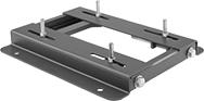
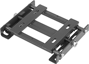
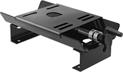
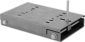
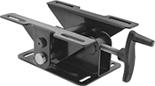
Maximize your belt-driven system’s efficiency while minimizing wear on bearings, pulleys, and other components. Made in the U.S., these adjustable mounts secure motors in the perfect position for proper belt tension. Make fine adjustments or tension the belt with a quick turn of the screw, hex nut, or hand crank. Choose a mount that fits the NEMA frame of your motor, which is listed on the nameplate.
Angular Adjustment—The right choice for applications with a 20° and greater angle between the motor and driven unit. Just turn a hex nut to tilt your motor up or down for better belt positioning.
For Constant Motor Speeds—These mounts keep motors tightly secured while operating equipment with a fixed speed, such as fans. You can only adjust the motor position when your system is off.
For Variable Motor Speeds—These mounts let you move the motor while the system runs to adjust for vibrations and varying loads. They’re best-suited for HVAC motors, cleated conveyors on an incline, and other systems with fluctuating power demands.
Automatic Tensioning—Mounts with automatic tensioning include shock-absorbing springs that compensate for bumps and vibrations, similar to the suspension in a car. Ideal for rock crushers and other machinery with irregular and challenging workloads, they reduce maintenance costs and help bearings, belts, and pullers last longer.
Style | For Motor Frame Size | For Max. Power, hp | Mounting Position | Max. Adjustment | Tilt Angle | Adjustment Mechanism | Tensioning Type | Lg. | Wd. | Ht. | Each | |||
|---|---|---|---|---|---|---|---|---|---|---|---|---|---|---|
For Linear Adjustment for Constant Motor Speeds | ||||||||||||||
| A | NEMA 143, NEMA 143T | 1 1/2 | Horizontal | 3" | — | Cap Screw | Manual | 10 1/2" | 7 1/2" | 1 1/8" | 62035K22 | 000000 | ||
| A | NEMA 145, NEMA 145T | 3 | Horizontal | 3" | — | Cap Screw | Manual | 10 1/2" | 8 1/2" | 1 1/8" | 62035K23 | 00000 | ||
| A | NEMA 182, NEMA 182T | 5 | Horizontal | 3" | — | Cap Screw | Manual | 12 3/4" | 9 1/2" | 1 1/2" | 62035K24 | 00000 | ||
| A | NEMA 184, NEMA 184T | 7 1/2 | Horizontal | 3" | — | Cap Screw | Manual | 12 3/4" | 10 1/2" | 1 1/2" | 62035K25 | 00000 | ||
| A | NEMA 213, NEMA 213T | 10 | Horizontal | 3 1/2" | — | Cap Screw | Manual | 15" | 11" | 1 3/4" | 62035K26 | 00000 | ||
| A | NEMA 215, NEMA 215T | 15 | Horizontal | 3 1/2" | — | Cap Screw | Manual | 15" | 12 1/2" | 1 3/4" | 62035K27 | 00000 | ||
| A | NEMA 48 | 3 | Horizontal | 3" | — | Cap Screw | Manual | 10" | 6 1/4" | 1 1/8" | 62035K201 | 00000 | ||
| A | NEMA 56 | 3 | Horizontal | 3" | — | Cap Screw | Manual | 10 5/8" | 6 1/2" | 1 1/8" | 62035K21 | 00000 | ||
| B | NEMA 254, NEMA 254T | 20 | Horizontal | 4" | — | Cap Screw | Manual | 17 3/4" | 15 1/8" | 2" | 62035K28 | 000000 | ||
| B | NEMA 256, NEMA 256T | 25 | Horizontal | 4" | — | Cap Screw | Manual | 17 3/4" | 16 7/8" | 2" | 62035K29 | 000000 | ||
| B | NEMA 284, NEMA 284T | 30 | Horizontal | 4 1/2" | — | Cap Screw | Manual | 19 3/4" | 16 7/8" | 2" | 62035K31 | 000000 | ||
| B | NEMA 286, NEMA 286T | 40 | Horizontal | 4 1/2" | — | Cap Screw | Manual | 19 3/4" | 18 3/8" | 2" | 62035K32 | 000000 | ||
| B | NEMA 324 | 50 | Horizontal | 5 1/4" | — | Cap Screw | Manual | 22 3/4" | 19 1/4" | 2 1/2" | 62035K202 | 000000 | ||
| B | NEMA 326 | 60 | Horizontal | 5 1/4" | — | Cap Screw | Manual | 22 3/4" | 20 3/4" | 2 1/2" | 62035K203 | 000000 | ||
| B | NEMA 364 | 75 | Horizontal | 6" | — | Cap Screw | Manual | 25 1/2" | 20 1/2" | 2 1/2" | 62035K204 | 000000 | ||
| B | NEMA 365 | 90 | Horizontal | 6" | — | Cap Screw | Manual | 25 1/2" | 21 1/2" | 2 1/2" | 62035K205 | 000000 | ||
| B | NEMA 404 | 120 | Horizontal | 7" | — | Cap Screw | Manual | 28 3/4" | 22 3/8" | 3" | 62035K206 | 000000 | ||
| B | NEMA 405 | 150 | Horizontal | 7" | — | Cap Screw | Manual | 28 3/4" | 23 7/8" | 3" | 62035K207 | 000000 | ||
| B | NEMA 444 | 200 | Horizontal | 7 1/2" | — | Cap Screw | Manual | 31 1/4" | 24 5/8" | 3" | 62035K208 | 000000 | ||
| B | NEMA 445 | 200 | Horizontal | 7 1/2" | — | Cap Screw | Manual | 31 1/4" | 26 5/8" | 3" | 62035K209 | 000000 | ||
| B | NEMA 447 | 200 | Horizontal | 7 1/2" | — | Cap Screw | Manual | 31 1/4" | 30 1/8" | 3" | 62035K211 | 000000 | ||
| B | NEMA 449 | 200 | Horizontal | 7 1/2" | — | Cap Screw | Manual | 31 1/4" | 35 1/8" | 3" | 62035K212 | 000000 | ||
For Linear Adjustment for Variable Motor Speeds | ||||||||||||||
| C | NEMA 143, NEMA 145 | 5 | Horizontal | 3" | — | Nut | Automatic | 11 11/16" | 8 1/4" | 1 7/8" | 62035K213 | 000000 | ||
| C | NEMA 182, NEMA 184 | 8 | Horizontal | 3" | — | Nut | Automatic | 14 1/16" | 9 3/8" | 2 1/8" | 62035K214 | 000000 | ||
| C | NEMA 213, NEMA 215 | 12 | Horizontal | 3 1/2" | — | Nut | Automatic | 16 3/8" | 11 3/8" | 2 9/16" | 62035K215 | 000000 | ||
| C | NEMA 254, NEMA 256 | 25 | Horizontal | 4" | — | Nut | Automatic | 19 1/2" | 15 1/4" | 3 1/8" | 62035K216 | 00000000 | ||
| C | NEMA 284, NEMA 286 | 35 | Horizontal | 5" | — | Nut | Automatic | 22 1/8" | 16 3/4" | 3 3/16" | 62035K217 | 00000000 | ||
| C | NEMA 48, NEMA 56 | 3 | Any Angle | 2 1/8" | — | Nut | Automatic | 9 1/2" | 5 7/8" | 1 3/8" | 61945K11 | 000000 | ||
| D | NEMA 48, NEMA 56 | 3 | Any Angle | 5 7/8" | — | Hand Crank | Manual | 13 1/8" | 6 1/4" | 3" | 6104K12 | 000000 | ||
| E | NEMA 143T, NEMA 145T, NEMA 182, NEMA 184, NEMA 48, NEMA 56, NEMA 56H, NEMA 66, NEMA 203 | 2 | Horizontal, Vertical | 8" | — | Hand Crank | Manual | 18 1/8" | 8" | 3 1/4" | 6531K12 | 000000 | ||
For Angular Adjustment for Constant Motor Speeds | ||||||||||||||
| F | NEMA 143, NEMA 145, NEMA 56 | 3 | Any Angle | — | 0° to 30° | Pivot | Manual | 15" | 8 3/8" | 3 1/2" | 62035K218 | 00000 | ||
| F | NEMA 182, NEMA 184, NEMA 213, NEMA 215 | 12 | Any Angle | — | 0° to 30° | Pivot | Manual | 16 3/4" | 11 7/8" | 3" | 62035K219 | 000000 | ||
| F | NEMA 254, NEMA 256, NEMA 284, NEMA 286 | 35 | Any Angle | — | 0° to 30° | Pivot | Manual | 20" | 16 5/8" | 3 5/8" | 62035K221 | 000000 | ||
For Angular Adjustment for Variable Motor Speeds | ||||||||||||||
| G | NEMA 48, NEMA 56 | 3 | Any Angle | — | 0° to 30° | Hand Crank | Manual | 12 1/2" | 5 7/8" | 3 1/2" | 6104K11 | 000000 | ||
Hydraulic Pump-to-Motor Mount Adapters
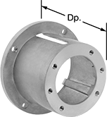 |
Mate a NEMA C-face motor to the mounting flange of a hydraulic pump. Mount adapters reduce noise and protect the shaft and coupling connection between the motor and the pump.
For SAE Pump Flange Size | For Motor Frame Size | Dp. | Mounting Flange Angle | Material | Each | ||
|---|---|---|---|---|---|---|---|
| AA | NEMA 56C, NEMA 143TC, NEMA 145TC, NEMA 182UC, NEMA 184UC | 3.53" | — | Aluminum | 4851N12 | 000000 | |
| AA | NEMA 56C, NEMA 143TC, NEMA 145TC | 4.25" | — | Aluminum | 62905K42 | 00000 | |
| AA | NEMA 182TC, NEMA 184TC, NEMA 213TC, NEMA 213UC, NEMA 215TC, NEMA 215UC, NEMA 254TC, NEMA 254UC, NEMA 256TC, NEMA 256UC | 5" | — | Aluminum | 4851N16 | 000000 | |
| AA | NEMA 182TC, NEMA 184TC, NEMA 213TC, NEMA 213UC, NEMA 215TC, NEMA 215UC, NEMA 254TC, NEMA 254UC, NEMA 256TC, NEMA 256UC | 5.88" | — | Aluminum | 4851N17 | 000000 | |
| A | NEMA 56C, NEMA 143TC, NEMA 145TC, NEMA 182UC, NEMA 184UC | 3.53" | — | Aluminum | 4851N13 | 00000 | |
| A | NEMA 56C, NEMA 143TC, NEMA 145TC | 4.25" | — | Aluminum | 62905K43 | 00000 | |
| A | NEMA 56C, NEMA 143TC, NEMA 145TC, NEMA 182UC, NEMA 184UC | 5" | — | Aluminum | 4851N14 | 000000 | |
| A | NEMA 182TC, NEMA 184TC, NEMA 213TC, NEMA 215TC, NEMA 254TC, NEMA 256TC | 5" | — | Aluminum | 62905K44 | 00000 | |
| A | NEMA 182TC, NEMA 184TC, NEMA 213TC, NEMA 215TC, NEMA 254TC, NEMA 256TC | 5.81" | — | Aluminum | 62905K45 | 00000 | |
| A | NEMA 182TC, NEMA 184TC, NEMA 213TC, NEMA 215TC, NEMA 254TC, NEMA 256TC | 6.81" | — | Aluminum | 62905K47 | 00000 | |
| A | NEMA 284TC, NEMA 284TSC, NEMA 284UC, NEMA 286TC, NEMA 286TSC, NEMA 286USC | 7.19" | — | Aluminum | 4851N23 | 000000 | |
| B | NEMA 56C, NEMA 143TC, NEMA 145TC, NEMA 182UC, NEMA 184UC | 4.25" | — | Aluminum | 4851N15 | 000000 | |
| B | NEMA 182TC, NEMA 184TC, NEMA 213TC, NEMA 213UC, NEMA 215TC, NEMA 215UC, NEMA 254TC, NEMA 254UC, NEMA 256TC, NEMA 256UC | 5" | — | Aluminum | 4851N18 | 00000 | |
| B | NEMA 182TC, NEMA 184TC, NEMA 213TC, NEMA 215TC, NEMA 254TC, NEMA 256TC | 5.81" | — | Aluminum | 62905K51 | 00000 | |
| B | NEMA 182TC, NEMA 184TC, NEMA 213TC, NEMA 213UC, NEMA 215TC, NEMA 215UC, NEMA 254TC, NEMA 254UC, NEMA 256TC, NEMA 256UC | 6.38" | 45° | Aluminum | 4851N21 | 000000 | |
| B | NEMA 182TC, NEMA 184TC, NEMA 213TC, NEMA 215TC, NEMA 254TC, NEMA 256TC | 6.81" | — | Aluminum | 62905K48 | 00000 | |
| B | NEMA 284TC, NEMA 284TSC, NEMA 284UC, NEMA 286TC, NEMA 286TSC, NEMA 286USC | 7.88" | — | Aluminum | 4851N24 | 000000 | |
| C | NEMA 182TC, NEMA 184TC, NEMA 213TC, NEMA 213UC, NEMA 215TC, NEMA 215UC, NEMA 254TC, NEMA 254UC, NEMA 256TC, NEMA 256UC | 6.38" | — | Aluminum | 4851N19 | 000000 | |
| C | NEMA 182TC, NEMA 184TC, NEMA 213TC, NEMA 213UC, NEMA 215TC, NEMA 215UC, NEMA 254TC, NEMA 254UC, NEMA 256TC, NEMA 256UC | 6.38" | 45° | Aluminum | 4851N22 | 000000 | |
| 4F17 | NEMA 56C, NEMA 143TC, NEMA 145TC, NEMA 182UC, NEMA 184UC | 3.53" | — | Aluminum | 4851N11 | 00000 | |
| 4F17 | NEMA 56C, NEMA 143TC, NEMA 145TC | 4.25" | — | Aluminum | 62905K41 | 00000 |
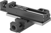
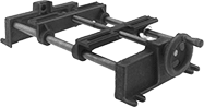
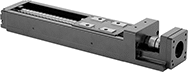
Dry-Running Positioning Slides for Stepper Motors
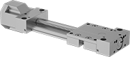 |
With PTFE sleeve bearings and a low-friction ball screw, these slides don’t require the mess and maintenance of lubrication but still give you precise positioning anywhere along the length of their stroke. Because they have sleeve bearings, they have fewer moving parts, so they perform better in dusty and wet environments than slides with ball bearings. They’re also better at handling impact and vibration.
All slides require a stepper motor, driver, and controller (not included) to operate. As part of this system, they move in precise increments, like the head on an inkjet printer. These positioning slides work well for automated assemblies and other applications that require fine, repeatable motion control.
Travel Distance per Turn—Travel distance per turn, also known as screw lead, is how far the carriage moves with one rotation of the ball screw.
Dynamic Load Cap. | For Max. Motor | Overall, mm | Carriage | |||||||||||||||||
|---|---|---|---|---|---|---|---|---|---|---|---|---|---|---|---|---|---|---|---|---|
Stroke Lg., mm | Horiz. | Vert. | Static Load Cap., lb. | Max. Speed, mm/s | Travel Distance per Turn, mm | Repeatability, mm | For Shaft Dia. | Speed, rpm | Torque, in·ozf | Lg. | Wd. | Ht. | Lg., mm | Wd., mm | Bearing Type | Base Material | Each | |||
For NEMA 17 Motor Frames | ||||||||||||||||||||
| 100 | Not Rated | Not Rated | 630 | 50 | 2 | -0.1 to 0.1 | 5 mm | 1,500 | 71 | 276 | 74 | 56 | 69 | 73 | Plain | Aluminum | 6650N11 | 0000000 | ||
| 200 | Not Rated | Not Rated | 630 | 50 | 2 | -0.1 to 0.1 | 5 mm | 1,500 | 71 | 376 | 74 | 56 | 69 | 73 | Plain | Aluminum | 6650N13 | 000000 | ||
| 300 | Not Rated | Not Rated | 630 | 50 | 2 | -0.1 to 0.1 | 5 mm | 1,500 | 71 | 476 | 74 | 56 | 69 | 73 | Plain | Aluminum | 6650N15 | 000000 | ||
| 400 | Not Rated | Not Rated | 630 | 50 | 2 | -0.1 to 0.1 | 5 mm | 1,500 | 71 | 576 | 74 | 56 | 69 | 73 | Plain | Aluminum | 6650N17 | 000000 | ||
| 500 | Not Rated | Not Rated | 630 | 50 | 2 | -0.1 to 0.1 | 5 mm | 1,500 | 71 | 676 | 74 | 56 | 69 | 73 | Plain | Aluminum | 6650N19 | 000000 | ||
| 600 | Not Rated | Not Rated | 630 | 50 | 2 | -0.1 to 0.1 | 5 mm | 1,500 | 71 | 776 | 74 | 56 | 69 | 73 | Plain | Aluminum | 6650N22 | 000000 | ||
For NEMA 23 Motor Frames | ||||||||||||||||||||
| 100 | Not Rated | Not Rated | 630 | 50 | 2 | -0.1 to 0.1 | 1/4" | 1,500 | 283 | 277 | 74 | 56 | 69 | 73 | Plain | Aluminum | 6650N12 | 000000 | ||
| 200 | Not Rated | Not Rated | 630 | 50 | 2 | -0.1 to 0.1 | 1/4" | 1,500 | 283 | 377 | 74 | 56 | 69 | 73 | Plain | Aluminum | 6650N14 | 000000 | ||
| 300 | Not Rated | Not Rated | 630 | 50 | 2 | -0.1 to 0.1 | 1/4" | 1,500 | 283 | 477 | 74 | 56 | 69 | 73 | Plain | Aluminum | 6650N16 | 000000 | ||
| 400 | Not Rated | Not Rated | 630 | 50 | 2 | -0.1 to 0.1 | 1/4" | 1,500 | 283 | 577 | 74 | 56 | 69 | 73 | Plain | Aluminum | 6650N18 | 000000 | ||
| 500 | Not Rated | Not Rated | 630 | 50 | 2 | -0.1 to 0.1 | 1/4" | 1,500 | 283 | 677 | 74 | 56 | 69 | 73 | Plain | Aluminum | 6650N21 | 000000 | ||
| 600 | Not Rated | Not Rated | 630 | 50 | 2 | -0.1 to 0.1 | 1/4" | 1,500 | 283 | 777 | 74 | 56 | 69 | 73 | Plain | Aluminum | 6650N23 | 000000 | ||
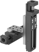
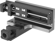
Positioning Slides for Stepper Motors
 |
Dynamic Load Cap., lb. | For Max. Motor | Overall, mm | Carriage | ||||||||||||||||
|---|---|---|---|---|---|---|---|---|---|---|---|---|---|---|---|---|---|---|---|
Stroke Lg., mm | Horiz. | Vert. | Max. Speed, mm/s | Travel Distance per Turn, mm | Repeatability, mm | For Shaft Dia. | Speed, rpm | Torque, in·ozf | Lg. | Wd. | Ht. | Lg., mm | Wd., mm | Bearing Type | Base Material | Each | |||
For NEMA 14 Motor Frames | |||||||||||||||||||
| 30 | 148 | 148 | 100 | 1 | -0.01 to 0.01 | 5 mm | 6,000 | 29.3 | 166 | 40 | 42 | 46 | 23 | Ball | Steel | 6734K211 | 0000000 | ||
| 80 | 148 | 148 | 100 | 1 | -0.01 to 0.01 | 5 mm | 6,000 | 29.3 | 216 | 40 | 42 | 46 | 23 | Ball | Steel | 6734K212 | 00000000 | ||
| 110 | 528 | 528 | 200 | 2 | -0.01 to 0.01 | 5 mm | 6,000 | 88.1 | 276 | 50 | 36 | 47.4 | 31 | Ball | Steel | 6734K214 | 00000000 | ||
| 130 | 148 | 148 | 100 | 1 | -0.01 to 0.01 | 5 mm | 6,000 | 29.3 | 266 | 40 | 42 | 46 | 23 | Ball | Steel | 6734K213 | 00000000 | ||
For NEMA 17 Motor Frames | |||||||||||||||||||
| 100 | 402 | 402 | 470 | 6 | -0.01 to 0.01 | 5 mm | 4,700 | 176 | 277 | 60 | 44.5 | 76 | 37.4 | Ball | Steel | 6734K811 | 00000000 | ||
| 110 | 528 | 528 | 200 | 2 | -0.01 to 0.01 | 5 mm | 6,000 | 88.1 | 276.5 | 50 | 42 | 47.4 | 31 | Ball | Steel | 6734K215 | 00000000 | ||
| 160 | 528 | 528 | 200 | 2 | -0.01 to 0.01 | 5 mm | 6,000 | 88.1 | 326.5 | 50 | 42 | 47.4 | 31 | Ball | Steel | 6734K216 | 00000000 | ||
| 200 | 402 | 402 | 470 | 6 | -0.01 to 0.01 | 5 mm | 4,700 | 176 | 377 | 60 | 44.5 | 76 | 37.4 | Ball | Steel | 6734K813 | 00000000 | ||
| 210 | 528 | 528 | 200 | 2 | -0.01 to 0.01 | 5 mm | 6,000 | 88.1 | 376.5 | 50 | 42 | 47.4 | 31 | Ball | Steel | 6734K217 | 00000000 | ||
For NEMA 23 Motor Frames | |||||||||||||||||||
| 100 | 402 | 402 | 470 | 6 | -0.01 to 0.01 | 1/4" | 4,700 | 176 | 280 | 60 | 56.4 | 76 | 37.4 | Ball | Steel | 6734K812 | 00000000 | ||
| 200 | 402 | 402 | 470 | 6 | -0.01 to 0.01 | 1/4" | 4,700 | 176 | 380 | 60 | 56.4 | 76 | 37.4 | Ball | Steel | 6734K814 | 00000000 | ||
| 300 | 395 | 395 | 790 | 10 | -0.01 to 0.01 | 1/4" | 6,000 | 176 | 480 | 60 | 56.4 | 76 | 37.4 | Ball | Steel | 6734K815 | 00000000 | ||
| 400 | 395 | 395 | 790 | 10 | -0.01 to 0.01 | 1/4" | 5,880 | 176 | 580 | 60 | 56.4 | 76 | 37.4 | Ball | Steel | 6734K816 | 00000000 | ||
| 500 | 395 | 395 | 650 | 10 | -0.01 to 0.01 | 1/4" | 3,900 | 176 | 680 | 60 | 56.4 | 76 | 37.4 | Ball | Steel | 6734K817 | 00000000 | ||
| 600 | 395 | 395 | 470 | 10 | -0.01 to 0.01 | 1/4" | 2,820 | 176 | 780 | 60 | 56.4 | 76 | 37.4 | Ball | Steel | 6734K818 | 00000000 | ||