


Filter by
System of Measurement
Motor Frame Size
Shaft Diameter
Maximum Holding Torque
Input Voltage
Voltage
Direction of Operation


Body Shape

Overall Width
Number of Shafts
Mounting Position
Face Shape
Export Control Classification Number (ECCN)
Mounting Location
RoHS
U.S.–Mexico–Canada Agreement (USMCA) Qualifying
DFARS Specialty Metals
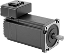
Stepper Servomotors with Integrated Drive
 |
Overall | Shaft | No. of Inputs/Outputs | |||||||||||||||||
|---|---|---|---|---|---|---|---|---|---|---|---|---|---|---|---|---|---|---|---|
Max. Holding Torque, in·ozf | Max. Rotation Speed, rpm | Voltage, V DC | Current, amp | Step Resolution | Full Step Increment | Lg. | Wd. | Ht. | Dia., mm | Lg., mm | Ctr.-to-Base Lg. | Communication Protocol | Digital Inputs | Digital Outputs | Enclosure Rating | Each | |||
NEMA 11 Frame Size | |||||||||||||||||||
| 9.2 | 3,000 | 15 to 30 | 0.9 | 1 to 1/256 | 1.8° | 2.7" | 1.1" | 1.5" | 5 | 13 | 0.57" | Modbus RTU | 4 | 2 | IP20 | 5361N11 | 0000000 | ||
| 11.3 | 3,000 | 15 to 30 | 1 | 1 to 1/256 | 1.8° | 3" | 1.1" | 1.5" | 5 | 13 | 0.57" | Modbus RTU | 4 | 2 | IP20 | 5361N12 | 000000 | ||
| 17.7 | 3,000 | 15 to 30 | 1 | 1 to 1/256 | 1.8° | 3.5" | 1.1" | 1.5" | 5 | 13 | 0.57" | Modbus RTU | 4 | 2 | IP20 | 5361N13 | 000000 | ||
Clean Room Stepper Motors
Motors
 |
 |  |
Maximum Holding Torque—Holding torque is the force needed to move the shaft out of position when it is stationary. When the shaft is in motion, torque generally decreases as speed increases. Use a torque-speed curve to confirm which motor will work for your application. Click on a part number and select “Product Detail” to view the curve for a motor.
Full Step Increment—Full step increment is the rotation of the shaft from one position to the next. A smaller full step increment means the rotor has more teeth, producing smoother and more precise motion. 1.8° is considered standard.
Overall | Shaft | Temp. Range, ° F | ||||||||||||||||||
|---|---|---|---|---|---|---|---|---|---|---|---|---|---|---|---|---|---|---|---|---|
Max. Holding Torque, in·ozf | Max. Rotation Speed, rpm | Max. Current per Phase, amp | Full Step Increment | Stepper Motor Polarity | No. of Wire Leads | Lg. | Wd. | Ht. | Dia., mm | Lg., mm | Type | No. of Shafts | Vacuum Rating, Torr | Min. | Max. | Clean Room Std. | Each | |||
Square Body | ||||||||||||||||||||
NEMA 11 Frame Size | ||||||||||||||||||||
| 10 | 3,250 | 0.67 | 1.8° | Bipolar | 4 | 2.1" | 1.1" | 1.1" | 5 | 18 | Solid | 1 | 1× 10^-7 | 0 | 120 | ISO Class 1 | 4799N11 | 000000000 | ||
| 19.5 | 1,550 | 0.67 | 1.8° | Bipolar | 4 | 2.8" | 1.1" | 1.1" | 5 | 18 | Solid | 1 | 1× 10^-7 | 0 | 120 | ISO Class 1 | 4799N12 | 00000000 | ||
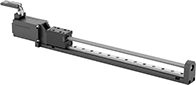
Electric Positioning Slides
 |
Dynamic Load Cap., lb. | Overall | Carriage | ||||||||||||||||
|---|---|---|---|---|---|---|---|---|---|---|---|---|---|---|---|---|---|---|
Horiz. | Vert. | Max. Speed, in/sec | Travel Distance per Full Step | Repeatability | Max. Current per Phase, amp | Full Step Increment | No. of Wire Leads | Lg. | Wd. | Ht. | Lg. | Wd. | Bearing Type | Base Material | Each | |||
4" Stroke Length | ||||||||||||||||||
| 20 | 15 | 1.4 | 0.00125" | -0.00125" to 0.00125" | 0.75 | 1.8° | 4 | 8.2" | 1.1" | 1.1" | 1.4" | 0.7" | Ball | Aluminum | 8739N12 | 000000000 | ||
| 20 | 30 | 0.3 | 0.000125" | -0.00012" to 0.00012" | 0.75 | 1.8° | 4 | 8.2" | 1.1" | 1.1" | 1.4" | 0.7" | Ball | Aluminum | 8739N11 | 00000000 | ||
8" Stroke Length | ||||||||||||||||||
| 20 | 15 | 1.4 | 0.00125" | -0.00125" to 0.00125" | 0.75 | 1.8° | 4 | 12.2" | 1.1" | 1.1" | 1.4" | 0.7" | Ball | Aluminum | 8739N14 | 00000000 | ||
| 20 | 30 | 0.3 | 0.000125" | -0.00012" to 0.00012" | 0.75 | 1.8° | 4 | 12.2" | 1.1" | 1.1" | 1.4" | 0.7" | Ball | Aluminum | 8739N13 | 00000000 | ||
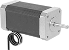
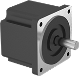
Stepper Motors
Motors
 |
Square Body |
 |
 |
These stepper motors are good for precise, repetitive movements, such as those made by the head of a 3D printer. Similar to the hands of a clock, their shaft turns in small, equal increments. When the shaft stops, it holds its position even when a counteracting force is applied to the load. You can control the position of the load without having to configure encoders or sensors. All are bipolar hybrid stepper motors, so the current can flow in both directions. This helps them deliver higher torque, precision, and efficiency than unipolar stepper motors.
All motors require a controller and drive (not included).
Maximum Holding Torque—Holding torque is the force needed to move the shaft out of position when it is stationary. When the shaft is in motion, torque generally decreases as speed increases. Use a torque-speed curve to confirm which motor will work for your application. Click on a part number and select “Product Detail” to view the curve for a motor.
Full Step Increment—Full step increment is the rotation of the shaft from one position to the next. A smaller full step increment means the rotor has more teeth, producing smoother and more precise motion. 1.8° is considered standard.
Overall | Shaft | Temp. Range, ° F | |||||||||||||||||
|---|---|---|---|---|---|---|---|---|---|---|---|---|---|---|---|---|---|---|---|
Max. Holding Torque, in·ozf | Max. Rotation Speed, rpm | Max. Current per Phase, amp | Full Step Increment | Stepper Motor Polarity | No. of Wire Leads | Lg. | Wd. | Ht. | Dia., mm | Lg., mm | Ctr.-to-Base Lg. | Type | No. of Shafts | Min. | Max. | Each | |||
Square Body | |||||||||||||||||||
NEMA 11 Frame Size | |||||||||||||||||||
| 8.5 | 3,300 | 0.67 | 1.8° | Bipolar | 4 | 2.1" | 1.1" | 1.1" | 5 | 18 | 0.56" | Solid | 1 | 0 | 120 | 6627T357 | 0000000 | ||
| 14 | 2,475 | 0.67 | 1.8° | Bipolar | 4 | 2.6" | 1.1" | 1.1" | 5 | 18 | 0.56" | Solid | 1 | 0 | 120 | 6627T356 | 000000 | ||
| 17 | 2,475 | 0.67 | 1.8° | Bipolar | 4 | 2.8" | 1.1" | 1.1" | 5 | 18 | 0.56" | Solid | 1 | 0 | 120 | 6627T355 | 000000 | ||
