


Filter by
System of Measurement

Thickness
Washer Type
Washer Designation
Performance
DFARS Specialty Metals
Export Control Classification Number (ECCN)
RoHS
Hardness
Military Specification
Certification
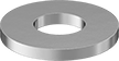
Mil. Spec. Washers
 |
Nickel
For Screw Size | ID | OD | Thk. | Mil. Spec. | Pkg. Qty. | Pkg. | |||
|---|---|---|---|---|---|---|---|---|---|
Highly Corrosion-Resistant 400 Nickel | |||||||||
| No. 1 | 0.078" | 0.188" | 0.016" to 0.025" | MS15795-401 | 25 | 97168A111 | 000000 | ||
| No. 2 | 0.094" | 0.250" | 0.016" to 0.025" | MS15795-402 | 25 | 97168A112 | 00000 | ||
| No. 4 | 0.125" | 0.250" | 0.017" to 0.028" | MS15795-403 | 25 | 97168A113 | 00000 | ||
| No. 4 | 0.125" | 0.312" | 0.025" to 0.040" | MS15795-404 | 25 | 97168A114 | 00000 | ||
| No. 6 | 0.156" | 0.312" | 0.027" to 0.048" | MS15795-405 | 25 | 97168A115 | 00000 | ||
| No. 8 | 0.188" | 0.375" | 0.036" to 0.065" | MS15795-407 | 10 | 97168A117 | 00000 | ||
| No. 8 | 0.188" | 0.438" | 0.036" to 0.065" | MS15795-441 | 10 | 97168A137 | 00000 | ||
| No. 10 | 0.219" | 0.438" | 0.036" to 0.065" | MS15795-408 | 10 | 97168A118 | 00000 | ||
| No. 10 | 0.219" | 0.500" | 0.036" to 0.065" | MS15795-442 | 10 | 97168A138 | 00000 | ||
| 1/4" | 0.281" | 0.625" | 0.051" to 0.080" | MS15795-410 | 5 | 97168A121 | 00000 | ||
| 1/4" | 0.312" | 0.734" | 0.051" to 0.080" | MS15795-411 | 5 | 97168A122 | 00000 | ||
| 3/8" | 0.406" | 0.625" | 0.051" to 0.080" | MS15795-448 | 5 | 97168A141 | 00000 | ||
| 3/8" | 0.406" | 0.812" | 0.051" to 0.080" | MS15795-414 | 1 | 97168A125 | 0000 | ||
| 7/16" | 0.500" | 0.875" | 0.058" to 0.070" | MS15795-449 | 1 | 97168A142 | 0000 | ||
| 1/2" | 0.531" | 1.062" | 0.074" to 0.121" | MS15795-418 | 1 | 97168A129 | 00000 | ||
| 5/8" | 0.688" | 1.750" | 0.108" to 0.160" | MS15795-421 | 1 | 97168A133 | 00000 | ||
| 3/4" | 0.812" | 1.469" | 0.108" to 0.160" | MS15795-422 | 1 | 97168A134 | 00000 | ||
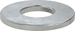
General Purpose Washers
 |
 |
Nickel
For Screw Size | ID | OD | Thk. | Pkg. Qty. | Pkg. | |||
|---|---|---|---|---|---|---|---|---|
Highly Corrosion-Resistant 400 Nickel | ||||||||
| 1/4" | 0.265" | 0.688" | 0.047" to 0.052" | 10 | 90785A029 | 000000 | ||
| 5/16" | 0.344" | 0.750" | 0.047" to 0.052" | 5 | 90785A030 | 00000 | ||
| 3/8" | 0.390" | 1.000" | 0.054" to 0.068" | 5 | 90785A031 | 00000 | ||
| 1/2" | 0.562" | 1.250" | 0.071" to 0.084" | 1 | 90785A033 | 0000 | ||
| 5/8" | 0.688" | 1.500" | 0.071" to 0.084" | 1 | 90785A035 | 00000 | ||
| 3/4" | 0.812" | 1.750" | 0.085" to 0.102" | 1 | 90785A036 | 00000 | ||
