


Filter by
Outlet Pressure
Maximum Outlet Pressure Gauge Measurement
Outlet Thread Type
Thread Type
Diaphragm Material
Maximum Pressure
Export Control Classification Number (ECCN)
DFARS Specialty Metals
RoHS
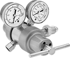
Tank-Mount Pressure-Regulating Valves for Air and Inert Gas
Single Stage
 | 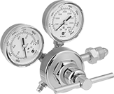 |  |  |
Female Outlet × Male Inlet Single-Stage Valves with T-Handle | Flared Outlet × Male Inlet Single-Stage Valves | UNF Male Outlet x Male Inlet Single-Stage Valves with T-Handle | UNF Male Outlet × Male Inlet Single-Stage Valves With Knob |
Inlet | Outlet | Material | |||||||||||||||||||||||||||||||||||||||||||||||||||||||||||||||||||||||||||||||||||||||||||||||||
|---|---|---|---|---|---|---|---|---|---|---|---|---|---|---|---|---|---|---|---|---|---|---|---|---|---|---|---|---|---|---|---|---|---|---|---|---|---|---|---|---|---|---|---|---|---|---|---|---|---|---|---|---|---|---|---|---|---|---|---|---|---|---|---|---|---|---|---|---|---|---|---|---|---|---|---|---|---|---|---|---|---|---|---|---|---|---|---|---|---|---|---|---|---|---|---|---|---|---|---|
CGA No. | Location | Thread Direction | Pressure Gauge Reading Range, psi | Location | Thread Direction | Pressure Range, psi | Pressure Adjustment Method | Body | Seal | Diaphragm | Temp. Range, ° F | Each | |||||||||||||||||||||||||||||||||||||||||||||||||||||||||||||||||||||||||||||||||||||||
For Argon, Helium, and Nitrogen | |||||||||||||||||||||||||||||||||||||||||||||||||||||||||||||||||||||||||||||||||||||||||||||||||||
37° Flared UNF Male Outlet × NGO Male Inlet | |||||||||||||||||||||||||||||||||||||||||||||||||||||||||||||||||||||||||||||||||||||||||||||||||||
| 580 | Side | Right Hand | 0 to 4,000 | Side | Right Hand | 10 to 200 | — | Brass | Polyurethane Rubber | Neoprene/Nylon | -20 to 120 | 66325A42 | 0000000 | ||||||||||||||||||||||||||||||||||||||||||||||||||||||||||||||||||||||||||||||||||||||
45° Flared UN/UNF (SAE 45°) Male Outlet × NGO Male Inlet | |||||||||||||||||||||||||||||||||||||||||||||||||||||||||||||||||||||||||||||||||||||||||||||||||||
| 580 | Side | Right Hand | 0 to 4,000 | Side | Right Hand | 0 to 250 | T-Handle | Brass | PTFE | Neoprene | -20 to 120 | 3687N113 | 000000 | ||||||||||||||||||||||||||||||||||||||||||||||||||||||||||||||||||||||||||||||||||||||
| 580 | Side | Right Hand | 0 to 4,000 | Side | Right Hand | 0 to 500 | T-Handle | Brass | PTFE | Neoprene | -20 to 120 | 66325A23 | 000000 | ||||||||||||||||||||||||||||||||||||||||||||||||||||||||||||||||||||||||||||||||||||||
5/8"-18 UNF Female Outlet × NGO Male Inlet | |||||||||||||||||||||||||||||||||||||||||||||||||||||||||||||||||||||||||||||||||||||||||||||||||||
| 580 | Side | Right Hand | 0 to 4,000 | Side | Right Hand | 0 to 125 | T-Handle | Brass | PTFE | Stainless Steel | -20 to 120 | 3687N117 | 000000 | ||||||||||||||||||||||||||||||||||||||||||||||||||||||||||||||||||||||||||||||||||||||
9/16"-18 UNF Male Outlet × NGO Male Inlet | |||||||||||||||||||||||||||||||||||||||||||||||||||||||||||||||||||||||||||||||||||||||||||||||||||
| 580 | Side | Right Hand | 0 to 4,000 | Side | Right Hand | 0 to 50 | T-Handle | Brass | PTFE | Neoprene | -20 to 120 | 3687N115 | 000000 | ||||||||||||||||||||||||||||||||||||||||||||||||||||||||||||||||||||||||||||||||||||||
| 580 | Side | Right Hand | 0 to 4,000 | Side | Right Hand | 0 to 125 | T-Handle | Brass | PTFE | Rubber | -20 to 120 | 7897A38 | 000000 | ||||||||||||||||||||||||||||||||||||||||||||||||||||||||||||||||||||||||||||||||||||||
| 580 | Side | Right Hand | 0 to 4,000 | Side | Right Hand | 0 to 145 | Knob | Brass/Steel | PTFE | Rubber | -20 to 120 | 7897A65 | 000000 | ||||||||||||||||||||||||||||||||||||||||||||||||||||||||||||||||||||||||||||||||||||||
| 580 | Side | Right Hand | 0 to 4,000 | Side | Right Hand | 0 to 200 | T-Handle | Brass | PTFE | Rubber | -20 to 120 | 7897A12 | 000000 | ||||||||||||||||||||||||||||||||||||||||||||||||||||||||||||||||||||||||||||||||||||||
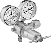
Two Stage
 |  |
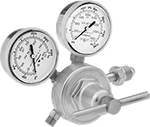
NPT Female Outlet × Male Inlet Two-Stage Valves with T-Handle | UNF Female Outlet x Male Inlet Two-Stage Valves with T-Handle |
Two-stage valves progressively reduce pressure over two steps for more consistent outlet pressure at all times. They’re often used in applications that require a constant outlet pressure regardless of the tank level.
Brass Body—Valves with a brass body have a longer service life than valves with a brass and steel body.
Stainless Steel Diaphragm—Valves with a stainless steel diaphragm can withstand harsh environments.
Inlet | Outlet | Material | |||||||||||||||||||||||||||||||||||||||||||||||||||||||||||||||||||||||||||||||||||||||||||||||||
|---|---|---|---|---|---|---|---|---|---|---|---|---|---|---|---|---|---|---|---|---|---|---|---|---|---|---|---|---|---|---|---|---|---|---|---|---|---|---|---|---|---|---|---|---|---|---|---|---|---|---|---|---|---|---|---|---|---|---|---|---|---|---|---|---|---|---|---|---|---|---|---|---|---|---|---|---|---|---|---|---|---|---|---|---|---|---|---|---|---|---|---|---|---|---|---|---|---|---|---|
CGA No. | Location | Thread Direction | Pressure Gauge Reading Range, psi | Location | Thread Direction | Pressure Range, psi | Pressure Adjustment Method | Body | Seal | Diaphragm | Temp. Range, ° F | Each | |||||||||||||||||||||||||||||||||||||||||||||||||||||||||||||||||||||||||||||||||||||||
For Argon, Helium, and Nitrogen | |||||||||||||||||||||||||||||||||||||||||||||||||||||||||||||||||||||||||||||||||||||||||||||||||||
1/4 NPT Female Outlet × NGO Male Inlet | |||||||||||||||||||||||||||||||||||||||||||||||||||||||||||||||||||||||||||||||||||||||||||||||||||
| 580 | Side | Right Hand | 0 to 4,000 | Side | Right Hand | 0 to 250 | T-Handle | Brass | PTFE | Neoprene | -20 to 120 | 3687N122 | 0000000 | ||||||||||||||||||||||||||||||||||||||||||||||||||||||||||||||||||||||||||||||||||||||
| 580 | Side | Right Hand | 0 to 4,000 | Side | Right Hand | 0 to 250 | T-Handle | Brass | PTFE | Stainless Steel | -20 to 120 | 3687N126 | 000000 | ||||||||||||||||||||||||||||||||||||||||||||||||||||||||||||||||||||||||||||||||||||||
5/8"-18 UNF Female Outlet × NGO Male Inlet | |||||||||||||||||||||||||||||||||||||||||||||||||||||||||||||||||||||||||||||||||||||||||||||||||||
| 580 | Side | Right Hand | 0 to 4,000 | Side | Right Hand | 0 to 50 | T-Handle | Brass | PTFE | Neoprene | -20 to 120 | 3687N121 | 000000 | ||||||||||||||||||||||||||||||||||||||||||||||||||||||||||||||||||||||||||||||||||||||
| 580 | Side | Right Hand | 0 to 4,000 | Side | Right Hand | 0 to 50 | T-Handle | Brass | PTFE | Stainless Steel | -20 to 120 | 7897A22 | 000000 | ||||||||||||||||||||||||||||||||||||||||||||||||||||||||||||||||||||||||||||||||||||||
| 580 | Side | Right Hand | 0 to 4,000 | Side | Right Hand | 0 to 125 | T-Handle | Brass/Steel | PTFE | Rubber | -20 to 120 | 7897A16 | 000000 | ||||||||||||||||||||||||||||||||||||||||||||||||||||||||||||||||||||||||||||||||||||||
| 580 | Side | Right Hand | 0 to 4,000 | Side | Right Hand | 0 to 125 | T-Handle | Brass | PTFE | Stainless Steel | -20 to 120 | 7897A23 | 000000 | ||||||||||||||||||||||||||||||||||||||||||||||||||||||||||||||||||||||||||||||||||||||
Tank-Mount Pressure-Regulating Valves for Moisture Removal
 |
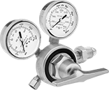
Designed for nitrogen gas purging in air conditioning, refrigeration, and plumbing systems, these valves automatically reduce a high inlet pressure to a lower, stable outlet pressure. They have Compressed Gas Association (CGA) numbered inlet fittings for secure connections to compressed gas tanks. Choose a valve with the same CGA number as your tank and other system components. Valves have 45° flared tube outlet fittings for a tight seal on metal tubing. They come with a gauge to monitor inlet pressure from the tank. They are single stage and reduce pressure in one step, which causes the outlet pressure to fluctuate slightly as you empty the tank.
Choose a valve with a maximum outlet pressure that’s approximately twice your application’s normal operating pressure. Your operating pressure should never exceed 75% of the valve’s maximum outlet pressure.
Inlet | Outlet | ||||||||||||||||||||||||||||||||||||||||||||||||||||||||||||||||||||||||||||||||||||||||||||||||||
|---|---|---|---|---|---|---|---|---|---|---|---|---|---|---|---|---|---|---|---|---|---|---|---|---|---|---|---|---|---|---|---|---|---|---|---|---|---|---|---|---|---|---|---|---|---|---|---|---|---|---|---|---|---|---|---|---|---|---|---|---|---|---|---|---|---|---|---|---|---|---|---|---|---|---|---|---|---|---|---|---|---|---|---|---|---|---|---|---|---|---|---|---|---|---|---|---|---|---|---|
CGA No. | Location | Thread Direction | Pressure Gauge Reading Range, psi | No. of Stages | For Tube OD | Location | Thread Direction | Purging Flow Range, ft³/hr | Brazing Flow Range, ft³/hr | Testing Pressure Range, psi | For Use With | Temp. Range, ° F | Each | ||||||||||||||||||||||||||||||||||||||||||||||||||||||||||||||||||||||||||||||||||||||
NGO Male Inlet × 45° Flared UN/UNF (SAE 45°) Male Outlet with 7/16"-20 End | |||||||||||||||||||||||||||||||||||||||||||||||||||||||||||||||||||||||||||||||||||||||||||||||||||
Brass Body—PTFE Seal | |||||||||||||||||||||||||||||||||||||||||||||||||||||||||||||||||||||||||||||||||||||||||||||||||||
| 580 | Side | Right Hand | 0 to 3,000 | Single | 1/4" | Side | Right Hand | 25 to 35 | 3 to 6 | 0 to 500 | Nitrogen | 32 to 120 | 66325A52 | 0000000 | |||||||||||||||||||||||||||||||||||||||||||||||||||||||||||||||||||||||||||||||||||||
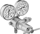
Easy-Read Tank-Mount Pressure-Regulating Valves with Flowmeter for Inert Gas
For Nitrogen
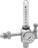 |
Male Inlet × Female Outlet With One Flowmeter |
Single Stage—Single-stage valves reduce pressure in one step, which causes the outlet pressure to fluctuate slightly as you empty the tank. They’re best for applications where a constant outlet pressure isn’t critical.
1 Flowmeter—Valves with one flowmeter are for one piece of equipment on a tank. The flowmeter has a single scale.
Inlet | Outlet | Material | |||||||||||||||||||||||||||||||||||||||||||||||||||||||||||||||||||||||||||||||||||||||||||||||||
|---|---|---|---|---|---|---|---|---|---|---|---|---|---|---|---|---|---|---|---|---|---|---|---|---|---|---|---|---|---|---|---|---|---|---|---|---|---|---|---|---|---|---|---|---|---|---|---|---|---|---|---|---|---|---|---|---|---|---|---|---|---|---|---|---|---|---|---|---|---|---|---|---|---|---|---|---|---|---|---|---|---|---|---|---|---|---|---|---|---|---|---|---|---|---|---|---|---|---|---|
CGA No. | Location | Thread Direction | Pressure Gauge Reading Range, psi | No. of Stages | Thread Size | Location | Thread Direction | Flow Range | No. of Flowmeters | Body | Seal | Diaphragm | Each | ||||||||||||||||||||||||||||||||||||||||||||||||||||||||||||||||||||||||||||||||||||||
UNF Female Outlet × NGO Male Inlet | |||||||||||||||||||||||||||||||||||||||||||||||||||||||||||||||||||||||||||||||||||||||||||||||||||
| 580 | Side | Right Hand | 0 to 4,000 | Single | 5/8"-18 | Side | Right Hand | 0 scfh to 100 scfh | 1 | Brass | PTFE | Neoprene | 78595A35 | 0000000 | |||||||||||||||||||||||||||||||||||||||||||||||||||||||||||||||||||||||||||||||||||||
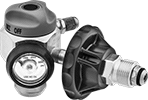
Tank-Mount Pressure-Regulating Valves for Cryogenic Cylinders
 |
Automatically reduce a high inlet pressure from compressed gas tanks to a lower, stable outlet pressure. These valves can remove gases from liquid cryogenic cylinders. They have Compressed Gas Association (CGA) numbered inlet fittings for secure connections to compressed gas tanks. Choose a valve with the same CGA number as your tank and other system components. Valves come with a gauge to monitor outlet pressure. They are single stage and reduce pressure in one step, which causes the outlet pressure to fluctuate slightly as you empty the tank.
Choose a valve with a maximum outlet pressure that’s approximately twice your application’s normal operating pressure. Your operating pressure should never exceed 75% of the valve’s maximum outlet pressure.
Inlet | Outlet | ||||||||||||||||||||||||||||||||||||||||||||||||||||||||||||||||||||||||||||||||||||||||||||||||||
|---|---|---|---|---|---|---|---|---|---|---|---|---|---|---|---|---|---|---|---|---|---|---|---|---|---|---|---|---|---|---|---|---|---|---|---|---|---|---|---|---|---|---|---|---|---|---|---|---|---|---|---|---|---|---|---|---|---|---|---|---|---|---|---|---|---|---|---|---|---|---|---|---|---|---|---|---|---|---|---|---|---|---|---|---|---|---|---|---|---|---|---|---|---|---|---|---|---|---|---|
For Use With | CGA No. | Location | Thread Direction | No. of Stages | Thread Size | Location | Thread Direction | Pressure Range, psi | Pressure Adjustment Method | Temp. Range, ° F | Each | ||||||||||||||||||||||||||||||||||||||||||||||||||||||||||||||||||||||||||||||||||||||||
UNF Male Outlet × NGO Male Inlet | |||||||||||||||||||||||||||||||||||||||||||||||||||||||||||||||||||||||||||||||||||||||||||||||||||
Brass Body—Stainless Steel Diaphragm and PTFE Seal | |||||||||||||||||||||||||||||||||||||||||||||||||||||||||||||||||||||||||||||||||||||||||||||||||||
| Nitrogen, Argon | 580 | Side | Right Hand | Single | 9/16"-18 | Bottom | Right Hand | 0 to 350 | T-Handle | -20 to 120 | 7897A87 | 0000000 | |||||||||||||||||||||||||||||||||||||||||||||||||||||||||||||||||||||||||||||||||||||||
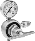
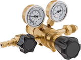
Tank-Mount High-Pressure-Regulating Valves for Air and Inert Gas
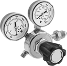
For Argon, Helium, and Nitrogen
 |  |
Female Outlet × Female Inlet Elbow With T-Handle | Female Outlet × Male Inlet Elbow With T-Handle |
Inlet | Outlet | Material | |||||||||||||||||||||||||||||||||||||||||||||||||||||||||||||||||||||||||||||||||||||||||||||||||
|---|---|---|---|---|---|---|---|---|---|---|---|---|---|---|---|---|---|---|---|---|---|---|---|---|---|---|---|---|---|---|---|---|---|---|---|---|---|---|---|---|---|---|---|---|---|---|---|---|---|---|---|---|---|---|---|---|---|---|---|---|---|---|---|---|---|---|---|---|---|---|---|---|---|---|---|---|---|---|---|---|---|---|---|---|---|---|---|---|---|---|---|---|---|---|---|---|---|---|---|
CGA No. | Location | Thread Direction | Pressure Gauge Reading Range, psi | No. of Stages | For Tube OD | Location | Pressure Range, psi | Pressure Adjustment Method | Shape | Body | Seal | Temp. Range, ° F | Each | ||||||||||||||||||||||||||||||||||||||||||||||||||||||||||||||||||||||||||||||||||||||
NGO Female Inlet × Swagelok® Female Outlet | |||||||||||||||||||||||||||||||||||||||||||||||||||||||||||||||||||||||||||||||||||||||||||||||||||
| 677 | Side | Left Hand | 0 to 7,500 | Single | 1/4" | Bottom | 300 to 4,500 | T-Handle | 90° Elbow | Brass | PCTFE | -20 to 120 | 6677A14 | 000000000 | |||||||||||||||||||||||||||||||||||||||||||||||||||||||||||||||||||||||||||||||||||||
NGO Male Inlet × Swagelok® Female Outlet | |||||||||||||||||||||||||||||||||||||||||||||||||||||||||||||||||||||||||||||||||||||||||||||||||||
| 580 | Side | Right Hand | 0 to 4,000 | Single | 1/4" | Bottom | 200 to 3,000 | T-Handle | 90° Elbow | Brass | PCTFE | -20 to 120 | 6677A13 | 000000 | |||||||||||||||||||||||||||||||||||||||||||||||||||||||||||||||||||||||||||||||||||||
High-Purity Tank-Mount Pressure-Regulating Valves for Inert Gas
For Argon, Helium, and Nitrogen
 | 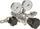 |
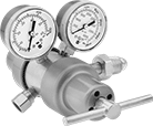
Swagelok® Female Outlet × NGO Male Inlet (Brass) | Swagelok® Female Outlet × NGO Male Inlet (Chrome-Plated Brass) |
Chrome-Plated Brass Body—Chrome-plated valves add a layer of corrosion resistance.
Single Stage—Single-stage valves reduce pressure in one step, which causes the outlet pressure to fluctuate slightly as you empty the tank. They’re best for applications where a constant outlet pressure isn’t critical.
Two Stage—Two-stage valves progressively reduce pressure over two steps for more consistent outlet pressure at all times. They’re often used in applications that require a constant outlet pressure regardless of the tank level.
Inlet | Outlet | ||||||||||||||||||||||||||||||||||||||||||||||||||||||||||||||||||||||||||||||||||||||||||||||||||
|---|---|---|---|---|---|---|---|---|---|---|---|---|---|---|---|---|---|---|---|---|---|---|---|---|---|---|---|---|---|---|---|---|---|---|---|---|---|---|---|---|---|---|---|---|---|---|---|---|---|---|---|---|---|---|---|---|---|---|---|---|---|---|---|---|---|---|---|---|---|---|---|---|---|---|---|---|---|---|---|---|---|---|---|---|---|---|---|---|---|---|---|---|---|---|---|---|---|---|---|
CGA No. | Location | Thread Direction | Pressure Gauge Reading Range, psi | No. of Stages | For Tube OD | Location | Pressure Range, psi | Pressure Adjustment Method | Temp. Range, ° F | Each | |||||||||||||||||||||||||||||||||||||||||||||||||||||||||||||||||||||||||||||||||||||||||
NGO Male Inlet × Swagelok® Female Outlet | |||||||||||||||||||||||||||||||||||||||||||||||||||||||||||||||||||||||||||||||||||||||||||||||||||
Brass Body—316 Stainless Steel Diaphragm and PTFE Seal | |||||||||||||||||||||||||||||||||||||||||||||||||||||||||||||||||||||||||||||||||||||||||||||||||||
| 580 | Side | Right Hand | 0 to 4,000 | Single | 1/4" | Side | 0 to 15 | Knob | -20 to 120 | 7951A14 | 0000000 | ||||||||||||||||||||||||||||||||||||||||||||||||||||||||||||||||||||||||||||||||||||||||
| 580 | Side | Right Hand | 0 to 4,000 | Single | 1/4" | Side | 0 to 125 | Knob | -20 to 120 | 7951A16 | 000000 | ||||||||||||||||||||||||||||||||||||||||||||||||||||||||||||||||||||||||||||||||||||||||
| 580 | Side | Right Hand | 0 to 4,000 | Single | 1/4" | Side | 0 to 500 | Knob | -20 to 120 | 7951A74 | 000000 | ||||||||||||||||||||||||||||||||||||||||||||||||||||||||||||||||||||||||||||||||||||||||
| 580 | Side | Right Hand | 0 to 4,000 | Two | 1/4" | Side | 0 to 15 | Knob | -20 to 120 | 7951A24 | 000000 | ||||||||||||||||||||||||||||||||||||||||||||||||||||||||||||||||||||||||||||||||||||||||
| 580 | Side | Right Hand | 0 to 4,000 | Two | 1/4" | Side | 0 to 50 | Knob | -20 to 120 | 7951A61 | 000000 | ||||||||||||||||||||||||||||||||||||||||||||||||||||||||||||||||||||||||||||||||||||||||
| 580 | Side | Right Hand | 0 to 4,000 | Two | 1/4" | Side | 0 to 125 | Knob | -20 to 120 | 7951A26 | 000000 | ||||||||||||||||||||||||||||||||||||||||||||||||||||||||||||||||||||||||||||||||||||||||
| 580 | Side | Right Hand | 0 to 4,000 | Two | 1/4" | Side | 0 to 250 | Knob | -20 to 120 | 7951A75 | 000000 | ||||||||||||||||||||||||||||||||||||||||||||||||||||||||||||||||||||||||||||||||||||||||
Chrome-Plated Brass Body—316 Stainless Steel Diaphragm and PTFE Seal | |||||||||||||||||||||||||||||||||||||||||||||||||||||||||||||||||||||||||||||||||||||||||||||||||||
| 580 | Side | Right Hand | 0 to 4,000 | Two | 1/4" | Side | 0 to 50 | Knob | -20 to 120 | 7951A62 | 000000 | ||||||||||||||||||||||||||||||||||||||||||||||||||||||||||||||||||||||||||||||||||||||||
