


Filter by
System of Measurement
Cooling Capacity
Voltage
Overall Width
Flow Capacity
Maximum Flow Rate
Shell Material
Maximum Temperature
Overall Height
Overall Length
Tube Material
Maximum Pressure
Heating/Cooling Capacity
Connects To
Material
Power
DFARS Specialty Metals
Export Control Classification Number (ECCN)
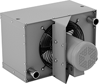
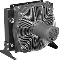
High-Capacity Heat Sinks for Oil
 |  |
Style A | Style B |
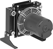
Totally Enclosed Nonventilated (TENV)—208V AC to 230V AC/460V AC, Three Phase
 |
Overall | |||||||||||||||||||||||||||||||||||||||||||||||||||||||||||||||||||||||||||||||||||||||||||||||||||
|---|---|---|---|---|---|---|---|---|---|---|---|---|---|---|---|---|---|---|---|---|---|---|---|---|---|---|---|---|---|---|---|---|---|---|---|---|---|---|---|---|---|---|---|---|---|---|---|---|---|---|---|---|---|---|---|---|---|---|---|---|---|---|---|---|---|---|---|---|---|---|---|---|---|---|---|---|---|---|---|---|---|---|---|---|---|---|---|---|---|---|---|---|---|---|---|---|---|---|---|
Cooling Cap., BTU/hr | Thread Size | Ht. | Wd. | Dp. | Heat Sink Material | Max. Pressure, psi | Max. Flow Rate, gpm | Max. Temp., ° F | Dash Size | Each | |||||||||||||||||||||||||||||||||||||||||||||||||||||||||||||||||||||||||||||||||||||||||
Female UN/UNF (SAE Straight) Thread—For Oil | |||||||||||||||||||||||||||||||||||||||||||||||||||||||||||||||||||||||||||||||||||||||||||||||||||
| 12,000 | 1 1/16"-12 | 13 3/4" | 13 3/4" | 12 9/16" | Aluminum | 377 | 30 | 250 | 12 | 3579K111 | 000000000 | ||||||||||||||||||||||||||||||||||||||||||||||||||||||||||||||||||||||||||||||||||||||||
| 20,000 | 1 1/16"-12 | 14 1/2" | 14 1/8" | 16 15/16" | Aluminum | 377 | 35 | 250 | 12 | 3579K21 | 00000000 | ||||||||||||||||||||||||||||||||||||||||||||||||||||||||||||||||||||||||||||||||||||||||
Totally Enclosed Fan-Cooled (TEFC)—208V AC to 230V AC/460V AC, Three Phase
| |
Style A | Style B |
Overall | Bolt Hole | ||||||||||||||||||||||||||||||||||||||||||||||||||||||||||||||||||||||||||||||||||||||||||||||||||
|---|---|---|---|---|---|---|---|---|---|---|---|---|---|---|---|---|---|---|---|---|---|---|---|---|---|---|---|---|---|---|---|---|---|---|---|---|---|---|---|---|---|---|---|---|---|---|---|---|---|---|---|---|---|---|---|---|---|---|---|---|---|---|---|---|---|---|---|---|---|---|---|---|---|---|---|---|---|---|---|---|---|---|---|---|---|---|---|---|---|---|---|---|---|---|---|---|---|---|---|
Style | Cooling Cap., BTU/hr | Thread Size | Ht. | Wd. | Dp. | SAE Pipe Flange Size | Dia. | No. of | Ctr.-to-Ctr. | Heat Sink Material | Max. Pressure, psi | Max. Flow Rate, gpm | Max. Temp., ° F | Dash Size | Each | ||||||||||||||||||||||||||||||||||||||||||||||||||||||||||||||||||||||||||||||||||||
Female UN/UNF (SAE Straight) Thread—For Oil | |||||||||||||||||||||||||||||||||||||||||||||||||||||||||||||||||||||||||||||||||||||||||||||||||||
| A | 7,500 | 1 5/16"-12 | 11 13/16" | 14 13/16" | 20" | — | — | — | — | Aluminum, Copper | 300 | 20 | 400 | 16 | 3579K101 | 000000000 | |||||||||||||||||||||||||||||||||||||||||||||||||||||||||||||||||||||||||||||||||||
| A | 13,800 | 1 5/16"-12 | 13 1/8" | 19" | 19 1/4" | — | — | — | — | Aluminum, Copper | 300 | 25 | 400 | 16 | 3579K102 | 00000000 | |||||||||||||||||||||||||||||||||||||||||||||||||||||||||||||||||||||||||||||||||||
| B | 27,000 | 1 5/16"-12 | 15 15/16" | 16 1/8" | 14 3/16" | — | — | — | — | Aluminum | 377 | 50 | 250 | 16 | 3579K22 | 00000000 | |||||||||||||||||||||||||||||||||||||||||||||||||||||||||||||||||||||||||||||||||||
| B | 32,000 | 1 5/16"-12 | 15 15/16" | 16 9/16" | 16" | — | — | — | — | Aluminum | 377 | 65 | 250 | 16 | 3579K112 | 00000000 | |||||||||||||||||||||||||||||||||||||||||||||||||||||||||||||||||||||||||||||||||||
| B | 44,000 | 1 5/8"-12 | 19 9/16" | 22" | 15 3/8" | — | — | — | — | Aluminum | 377 | 60 | 250 | 20 | 3579K113 | 00000000 | |||||||||||||||||||||||||||||||||||||||||||||||||||||||||||||||||||||||||||||||||||
| B | 76,000 | 1 5/8"-12 | 24" | 25 9/16" | 16 3/4" | — | — | — | — | Aluminum | 377 | 65 | 250 | 20 | 3579K23 | 00000000 | |||||||||||||||||||||||||||||||||||||||||||||||||||||||||||||||||||||||||||||||||||
| B | 90,000 | 1 5/8"-12 | 24" | 26 3/8" | 18" | — | — | — | — | Aluminum | 377 | 75 | 250 | 20 | 3579K24 | 00000000 | |||||||||||||||||||||||||||||||||||||||||||||||||||||||||||||||||||||||||||||||||||
| B | 126,000 | 1 5/8"-12 | 25 7/8" | 30 5/16" | 19 1/2" | — | — | — | — | Aluminum | 377 | 80 | 250 | 20 | 3579K114 | 00000000 | |||||||||||||||||||||||||||||||||||||||||||||||||||||||||||||||||||||||||||||||||||
SAE Flange—For Oil | |||||||||||||||||||||||||||||||||||||||||||||||||||||||||||||||||||||||||||||||||||||||||||||||||||
| B | 205,000 | — | 30 3/16" | 37" | 23 3/16" | 2 | 0.51" | 4 | 1.688" to 3.062" | Aluminum | 377 | 115 | 250 | — | 3579K116 | 00000000 | |||||||||||||||||||||||||||||||||||||||||||||||||||||||||||||||||||||||||||||||||||
| B | 238,000 | — | 33 1/4" | 39" | 23 3/8" | 2 | 0.51" | 4 | 1.688" to 3.062" | Aluminum | 377 | 120 | 250 | — | 3579K117 | 00000000 | |||||||||||||||||||||||||||||||||||||||||||||||||||||||||||||||||||||||||||||||||||
| B | 356,000 | — | 38 3/8" | 43 5/8" | 29 1/2" | 2 | 0.51" | 4 | 1.688" to 3.062" | Aluminum | 250 | 150 | 250 | — | 3579K119 | 000000000 | |||||||||||||||||||||||||||||||||||||||||||||||||||||||||||||||||||||||||||||||||||
Heat Sinks for Oil
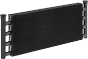 |
Dozens of fins and coolant tubes quickly dissipate excess heat. Also known as oil coolers, these heat sinks cool hydraulic fluid and lubricating oil in cylinders and compressors. Cooling and flow capacities are based on 50 SSU oil, 1,000 feet per minute of air, a 50° F initial temperature difference, and a 10 psi pressure drop.
Bypass—Heat sinks with a bypass prevent damage to the cooling fins by diverting pressurized oil. They’re often used in machines that are started up while cold. Once the oil heats up and the pressure drops, flow through the cooling tubes resumes.
Overall | |||||||||||||||||||||||||||||||||||||||||||||||||||||||||||||||||||||||||||||||||||||||||||||||||||
|---|---|---|---|---|---|---|---|---|---|---|---|---|---|---|---|---|---|---|---|---|---|---|---|---|---|---|---|---|---|---|---|---|---|---|---|---|---|---|---|---|---|---|---|---|---|---|---|---|---|---|---|---|---|---|---|---|---|---|---|---|---|---|---|---|---|---|---|---|---|---|---|---|---|---|---|---|---|---|---|---|---|---|---|---|---|---|---|---|---|---|---|---|---|---|---|---|---|---|---|
Cooling Cap., BTU/hr | Pipe Size | Thread Type | Gender | Ht. | Wd. | Dp. | Heat Sink Material | Max. Pressure, psi | Max. Flow Rate, gpm | Max. Temp., ° F | Fitting Connection | No. of Mounting Kits Req. | Each | ||||||||||||||||||||||||||||||||||||||||||||||||||||||||||||||||||||||||||||||||||||||
Copper Tube—For Oil | |||||||||||||||||||||||||||||||||||||||||||||||||||||||||||||||||||||||||||||||||||||||||||||||||||
| 3,300 | 1/2 | NPT | Female | 4 1/2" | 15" | 1 1/2" | Aluminum | 300 | 7 | 350 | Threaded | 2 | 3525K11 | 0000000 | |||||||||||||||||||||||||||||||||||||||||||||||||||||||||||||||||||||||||||||||||||||
| 6,100 | 1/2 | NPT | Female | 6 1/2" | 18" | 1 1/2" | Aluminum | 300 | 9 | 350 | Threaded | 4 | 3525K21 | 000000 | |||||||||||||||||||||||||||||||||||||||||||||||||||||||||||||||||||||||||||||||||||||
| 8,100 | 1/2 | NPT | Female | 6 1/2" | 24" | 1 1/2" | Aluminum | 300 | 7 | 350 | Threaded | 4 | 3525K12 | 000000 | |||||||||||||||||||||||||||||||||||||||||||||||||||||||||||||||||||||||||||||||||||||
| 9,600 | 1/2 | NPT | Female | 8 1/2" | 21" | 1 1/2" | Aluminum | 300 | 11 | 350 | Threaded | 4 | 3525K13 | 000000 | |||||||||||||||||||||||||||||||||||||||||||||||||||||||||||||||||||||||||||||||||||||
| 11,800 | 3/4 | NPT | Female | 12 3/4" | 18" | 1 1/2" | Aluminum | 300 | 19 | 350 | Threaded | 4 | 3525K14 | 000000 | |||||||||||||||||||||||||||||||||||||||||||||||||||||||||||||||||||||||||||||||||||||
| 24,000 | 3/4 | NPT | Female | 18 3/4" | 24" | 1 1/2" | Aluminum | 300 | 22 | 350 | Threaded | 6 | 3525K25 | 000000 | |||||||||||||||||||||||||||||||||||||||||||||||||||||||||||||||||||||||||||||||||||||
| 31,000 | 1 | NPT | Female | 25" | 24" | 1 1/2" | Aluminum | 300 | 28 | 350 | Threaded | 8 | 3525K26 | 000000 | |||||||||||||||||||||||||||||||||||||||||||||||||||||||||||||||||||||||||||||||||||||
| 49,000 | 1 | NPT | Female | 31" | 30" | 1 1/2" | Aluminum | 300 | 30 | 350 | Threaded | 8 | 3525K27 | 000000 | |||||||||||||||||||||||||||||||||||||||||||||||||||||||||||||||||||||||||||||||||||||
| 57,000 | 1 1/4 | NPT | Female | 37 7/16" | 30" | 1 1/2" | Aluminum | 300 | 36 | 350 | Threaded | 8 | 3525K28 | 00000000 | |||||||||||||||||||||||||||||||||||||||||||||||||||||||||||||||||||||||||||||||||||||
Copper Tube with Bypass—For Oil | |||||||||||||||||||||||||||||||||||||||||||||||||||||||||||||||||||||||||||||||||||||||||||||||||||
| 3,400 | 1/2 | NPT | Female | 4 1/2" | 15" | 1 1/2" | Aluminum | 300 | 7 | 350 | Threaded | 2 | 3525K101 | 000000 | |||||||||||||||||||||||||||||||||||||||||||||||||||||||||||||||||||||||||||||||||||||
| 6,300 | 1/2 | NPT | Female | 6 1/2" | 18 1/4" | 1 1/2" | Aluminum | 300 | 9 | 350 | Threaded | 4 | 3525K102 | 000000 | |||||||||||||||||||||||||||||||||||||||||||||||||||||||||||||||||||||||||||||||||||||
| 10,000 | 1/2 | NPT | Female | 8 1/2" | 21" | 1 1/2" | Aluminum | 300 | 11 | 350 | Threaded | 4 | 3525K103 | 000000 | |||||||||||||||||||||||||||||||||||||||||||||||||||||||||||||||||||||||||||||||||||||
| 12,000 | 3/4 | NPT | Female | 12 3/4" | 18" | 1 1/2" | Aluminum | 300 | 9 | 350 | Threaded | 4 | 3525K104 | 000000 | |||||||||||||||||||||||||||||||||||||||||||||||||||||||||||||||||||||||||||||||||||||
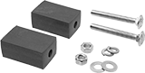 |
Mounting kits are required for installation.
Includes | Each | ||
|---|---|---|---|
| Two Carriage Bolts, Two Flat Washers, Two Lock Washers, Two Nuts, Two Rubber Blocks | 3525K41 | 000000 |
Heat Exchangers
NPT Female Threaded Shell-Side and Tube-Side Connections
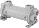 |
316 Stainless Steel Shell—Heat exchangers with a 316 stainless steel shell are the most corrosion resistant.
Baffled Tubes—Heat exchangers with baffled tubes direct liquid to make four passes through the tubes for more efficient heat transfer than other heat exchangers.
316 Stainless Steel Tube—Heat exchangers with 316 stainless steel tubes are the most corrosion resistant.
Heating/Cooling Capacity—Btu/hr. cooling capacity is based on cooling 180° F process water with 85° F water and a 10 psi pressure difference.
Temp., ° F | Shell-Side | Tube Side | Overall | ||||||||||||||||||||||||||||||||||||||||||||||||||||||||||||||||||||||||||||||||||||||||||||||||
|---|---|---|---|---|---|---|---|---|---|---|---|---|---|---|---|---|---|---|---|---|---|---|---|---|---|---|---|---|---|---|---|---|---|---|---|---|---|---|---|---|---|---|---|---|---|---|---|---|---|---|---|---|---|---|---|---|---|---|---|---|---|---|---|---|---|---|---|---|---|---|---|---|---|---|---|---|---|---|---|---|---|---|---|---|---|---|---|---|---|---|---|---|---|---|---|---|---|---|---|
Heating/Cooling Cap., BTU/hr | Surface Area, ft² | No. of Passes | Min. | Max. | Pipe Size | Flow Cap., gpm | Max. Pressure, psi | Pipe Size | Flow Cap., gpm | Max. Pressure, psi | Lg. | Head Dia. | Each | ||||||||||||||||||||||||||||||||||||||||||||||||||||||||||||||||||||||||||||||||||||||
Brass Shell and Baffled Copper Tube | |||||||||||||||||||||||||||||||||||||||||||||||||||||||||||||||||||||||||||||||||||||||||||||||||||
| 130,000 | 2.4 | 4 | -20 | 300 | 1 | 24 | 300 | 3/4 | 12 | 150 | 10 7/8" | 4 3/16" | 34965K52 | 000000000 | |||||||||||||||||||||||||||||||||||||||||||||||||||||||||||||||||||||||||||||||||||||
| 195,000 | 4.3 | 4 | -20 | 300 | 1 | 24 | 300 | 3/4 | 12 | 150 | 16 7/8" | 4 3/16" | 34965K53 | 00000000 | |||||||||||||||||||||||||||||||||||||||||||||||||||||||||||||||||||||||||||||||||||||
| 280,000 | 7.4 | 4 | -20 | 300 | 1 | 24 | 300 | 3/4 | 12 | 150 | 26 7/8" | 4 3/16" | 34965K54 | 00000000 | |||||||||||||||||||||||||||||||||||||||||||||||||||||||||||||||||||||||||||||||||||||
| 350,000 | 9.1 | 4 | -20 | 300 | 1 1/2 | 60 | 300 | 1 | 30 | 150 | 18 1/8" | 6 1/2" | 34965K55 | 00000000 | |||||||||||||||||||||||||||||||||||||||||||||||||||||||||||||||||||||||||||||||||||||
| 560,000 | 15.7 | 4 | -20 | 300 | 1 1/2 | 60 | 300 | 1 | 30 | 150 | 28 1/8" | 6 1/2" | 34965K56 | 00000000 | |||||||||||||||||||||||||||||||||||||||||||||||||||||||||||||||||||||||||||||||||||||
| 890,000 | 23 | 4 | -20 | 300 | 2 | 73 | 300 | 1 1/2 | 57 | 150 | 29" | 7 1/2" | 34965K57 | 00000000 | |||||||||||||||||||||||||||||||||||||||||||||||||||||||||||||||||||||||||||||||||||||
| 1,115,000 | 34 | 4 | -20 | 300 | 2 | 73 | 300 | 1 1/2 | 57 | 150 | 41" | 7 1/2" | 34965K58 | 00000000 | |||||||||||||||||||||||||||||||||||||||||||||||||||||||||||||||||||||||||||||||||||||
| 1,585,000 | 41 | 4 | -20 | 300 | 3 | 140 | 300 | 2 | 104 | 150 | 30 3/8" | 9 3/4" | 34965K59 | 00000000 | |||||||||||||||||||||||||||||||||||||||||||||||||||||||||||||||||||||||||||||||||||||
| 2,000,000 | 62 | 4 | -20 | 300 | 3 | 140 | 300 | 2 | 105 | 150 | 42 3/8" | 9 3/4" | 34965K61 | 00000000 | |||||||||||||||||||||||||||||||||||||||||||||||||||||||||||||||||||||||||||||||||||||
Steel Shell and Baffled Copper Tube | |||||||||||||||||||||||||||||||||||||||||||||||||||||||||||||||||||||||||||||||||||||||||||||||||||
| 195,000 | 4.3 | 4 | -20 | 300 | 1 | 22 | 300 | 3/4 | 12 | 150 | 17" | 4 1/2" | 3222K53 | 00000000 | |||||||||||||||||||||||||||||||||||||||||||||||||||||||||||||||||||||||||||||||||||||
| 280,000 | 7.4 | 4 | -20 | 300 | 1 | 30 | 300 | 3/4 | 12 | 150 | 27" | 4 1/2" | 3222K54 | 00000000 | |||||||||||||||||||||||||||||||||||||||||||||||||||||||||||||||||||||||||||||||||||||
| 350,000 | 9.1 | 4 | -20 | 300 | 1 1/2 | 32 | 300 | 1 | 30 | 150 | 18 11/16" | 6 3/4" | 3222K55 | 00000000 | |||||||||||||||||||||||||||||||||||||||||||||||||||||||||||||||||||||||||||||||||||||
| 560,000 | 15.7 | 4 | -20 | 300 | 1 1/2 | 43 | 300 | 1 | 30 | 150 | 28 11/16" | 6 3/4" | 3222K56 | 00000000 | |||||||||||||||||||||||||||||||||||||||||||||||||||||||||||||||||||||||||||||||||||||
| 890,000 | 23 | 4 | -20 | 300 | 2 | 51 | 300 | 1 1/2 | 57 | 150 | 29" | 7 3/4" | 3222K57 | 00000000 | |||||||||||||||||||||||||||||||||||||||||||||||||||||||||||||||||||||||||||||||||||||
| 1,115,000 | 34 | 4 | -20 | 300 | 2 | 103 | 300 | 1 1/2 | 57 | 150 | 41" | 7 3/4" | 3222K58 | 00000000 | |||||||||||||||||||||||||||||||||||||||||||||||||||||||||||||||||||||||||||||||||||||
| 1,585,000 | 41 | 4 | -20 | 300 | 3 | 103 | 300 | 2 | 104 | 150 | 30 1/2" | 10 1/2" | 3222K59 | 00000000 | |||||||||||||||||||||||||||||||||||||||||||||||||||||||||||||||||||||||||||||||||||||
| 2,000,000 | 62 | 4 | -20 | 300 | 3 | 103 | 300 | 2 | 105 | 150 | 42 1/2" | 10 1/2" | 3222K61 | 00000000 | |||||||||||||||||||||||||||||||||||||||||||||||||||||||||||||||||||||||||||||||||||||
Steel Shell and Copper Tube | |||||||||||||||||||||||||||||||||||||||||||||||||||||||||||||||||||||||||||||||||||||||||||||||||||
| Not Rated | 15 | 2 | Not Rated | 400 | 2 1/2 (Inlet); 1 1/4 (Outlet) | 38 | 100 | 1 1/4 | 38 | 100 | 28 5/8" | 6" | 3586K31 | 00000000 | |||||||||||||||||||||||||||||||||||||||||||||||||||||||||||||||||||||||||||||||||||||
316 Stainless Steel Shell and Baffled 316 Stainless Steel Tube | |||||||||||||||||||||||||||||||||||||||||||||||||||||||||||||||||||||||||||||||||||||||||||||||||||
| 130,000 | 2.4 | 4 | -20 | 450 | 1 | 32 | 225 | 3/4 | 12 | 150 | 10 3/8" | 4 3/16" | 35185K42 | 00000000 | |||||||||||||||||||||||||||||||||||||||||||||||||||||||||||||||||||||||||||||||||||||
| 195,000 | 4.3 | 4 | -20 | 450 | 1 | 32 | 225 | 3/4 | 12 | 150 | 16 3/8" | 4 3/16" | 35185K43 | 00000000 | |||||||||||||||||||||||||||||||||||||||||||||||||||||||||||||||||||||||||||||||||||||
| 280,000 | 7.4 | 4 | -20 | 450 | 1 | 32 | 225 | 3/4 | 12 | 150 | 26 3/8" | 4 3/16" | 35185K44 | 00000000 | |||||||||||||||||||||||||||||||||||||||||||||||||||||||||||||||||||||||||||||||||||||
| 350,000 | 9.1 | 4 | -20 | 450 | 1 1/2 | 76 | 225 | 1 | 30 | 150 | 17 13/16" | 6 1/2" | 35185K45 | 00000000 | |||||||||||||||||||||||||||||||||||||||||||||||||||||||||||||||||||||||||||||||||||||
| 560,000 | 15.7 | 4 | -20 | 450 | 1 1/2 | 76 | 225 | 1 | 30 | 150 | 27 13/16" | 6 1/2" | 35185K46 | 00000000 | |||||||||||||||||||||||||||||||||||||||||||||||||||||||||||||||||||||||||||||||||||||
| 890,000 | 23 | 4 | -20 | 450 | 2 | 126 | 225 | 1 1/2 | 57 | 150 | 28 1/8" | 7 1/2" | 35185K47 | 00000000 | |||||||||||||||||||||||||||||||||||||||||||||||||||||||||||||||||||||||||||||||||||||
| 1,115,000 | 34 | 4 | -20 | 450 | 2 | 126 | 225 | 1 1/2 | 57 | 150 | 40 1/8" | 7 1/2" | 35185K48 | 00000000 | |||||||||||||||||||||||||||||||||||||||||||||||||||||||||||||||||||||||||||||||||||||
| 1,585,000 | 41 | 4 | -20 | 450 | 3 | 220 | 225 | 2 | 104 | 150 | 28" | 9 3/4" | 35185K49 | 00000000 | |||||||||||||||||||||||||||||||||||||||||||||||||||||||||||||||||||||||||||||||||||||
| 2,000,000 | 62 | 4 | -20 | 450 | 3 | 220 | 225 | 2 | 105 | 150 | 40" | 9 3/4" | 35185K51 | 00000000 | |||||||||||||||||||||||||||||||||||||||||||||||||||||||||||||||||||||||||||||||||||||
NPT Female Threaded Shell-Side and Tube-Side Connections—ASME BPVC.VIII.1 Certified
|
ASME BPVC VIII.1 heat exchangers meet the ASME Boiler and Pressure Vessel Code (BPVC) for construction of pressure vessels.
Heating/Cooling Capacity—Btu/hr. cooling capacity is based on cooling 180° F process water with 85° F water and a 10 psi pressure difference.
Temp., ° F | Shell-Side | Tube Side | Overall | ||||||||||||||||||||||||||||||||||||||||||||||||||||||||||||||||||||||||||||||||||||||||||||||||
|---|---|---|---|---|---|---|---|---|---|---|---|---|---|---|---|---|---|---|---|---|---|---|---|---|---|---|---|---|---|---|---|---|---|---|---|---|---|---|---|---|---|---|---|---|---|---|---|---|---|---|---|---|---|---|---|---|---|---|---|---|---|---|---|---|---|---|---|---|---|---|---|---|---|---|---|---|---|---|---|---|---|---|---|---|---|---|---|---|---|---|---|---|---|---|---|---|---|---|---|
Heating/Cooling Cap., BTU/hr | Surface Area, ft² | No. of Passes | Min. | Max. | Pipe Size | Flow Cap., gpm | Max. Pressure, psi | Pipe Size | Flow Cap., gpm | Max. Pressure, psi | Lg. | Head Dia. | Each | ||||||||||||||||||||||||||||||||||||||||||||||||||||||||||||||||||||||||||||||||||||||
Steel Shell and Copper Tube | |||||||||||||||||||||||||||||||||||||||||||||||||||||||||||||||||||||||||||||||||||||||||||||||||||
| 150,000 | 4.5 | 2 | -20 | 375 | 2 (Inlet); 1 (Outlet) | 44 | 150 | 1 1/2 | 44 | 150 | 28 1/2" | 7 1/4" | 3586K41 | 000000000 | |||||||||||||||||||||||||||||||||||||||||||||||||||||||||||||||||||||||||||||||||||||
| 420,000 | 6.8 | 2 | -20 | 375 | 2 (Inlet); 1 (Outlet) | 44 | 150 | 1 1/2 | 44 | 150 | 40 1/2" | 7 1/4" | 3586K42 | 00000000 | |||||||||||||||||||||||||||||||||||||||||||||||||||||||||||||||||||||||||||||||||||||
| 720,000 | 9.2 | 2 | -20 | 375 | 3 (Inlet); 1 (Outlet) | 44 | 150 | 1 1/2 | 44 | 150 | 52 1/2" | 7 1/4" | 3586K43 | 00000000 | |||||||||||||||||||||||||||||||||||||||||||||||||||||||||||||||||||||||||||||||||||||
| 1,350,000 | 17.4 | 2 | -20 | 375 | 2 1/2 (Inlet); 1 (Outlet) | 175 | 150 | 2 | 175 | 150 | 53 1/4" | 10 1/2" | 3586K44 | 00000000 | |||||||||||||||||||||||||||||||||||||||||||||||||||||||||||||||||||||||||||||||||||||
NPT Female Flanged Shell-Side Inlet Connections and Threaded Tube-Side Connections
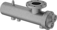 |
Heating/Cooling Capacity—Btu/hr. cooling capacity is based on cooling 180° F process water with 85° F water and a 10 psi pressure difference.
Temp. | Shell-Side | Tube Side | Overall | ||||||||||||||||||||||||||||||||||||||||||||||||||||||||||||||||||||||||||||||||||||||||||||||||
|---|---|---|---|---|---|---|---|---|---|---|---|---|---|---|---|---|---|---|---|---|---|---|---|---|---|---|---|---|---|---|---|---|---|---|---|---|---|---|---|---|---|---|---|---|---|---|---|---|---|---|---|---|---|---|---|---|---|---|---|---|---|---|---|---|---|---|---|---|---|---|---|---|---|---|---|---|---|---|---|---|---|---|---|---|---|---|---|---|---|---|---|---|---|---|---|---|---|---|---|
Heating/Cooling Cap. | Surface Area, ft² | No. of Passes | Min. | Max., ° F | Pipe Size | Flow Cap., gpm | Max. Pressure, psi | Pipe Size | Flow Cap., gpm | Max. Pressure, psi | Lg. | Head Dia. | Each | ||||||||||||||||||||||||||||||||||||||||||||||||||||||||||||||||||||||||||||||||||||||
Steel Shell and Copper Tube | |||||||||||||||||||||||||||||||||||||||||||||||||||||||||||||||||||||||||||||||||||||||||||||||||||
| Not Rated | 30.2 | 2 | Not Rated | 400 | 4 (Inlet); 1 1/2 (Outlet) | 100 | 100 | 2 | 100 | 100 | 39 3/4" | 8 1/8" | 3586K33 | 000000000 | |||||||||||||||||||||||||||||||||||||||||||||||||||||||||||||||||||||||||||||||||||||
| Not Rated | 38.8 | 2 | Not Rated | 400 | 4 (Inlet); 1 1/2 (Outlet) | 100 | 100 | 2 | 100 | 100 | 51 3/4" | 8 1/8" | 3586K34 | 00000000 | |||||||||||||||||||||||||||||||||||||||||||||||||||||||||||||||||||||||||||||||||||||
| Not Rated | 72.4 | 2 | Not Rated | 400 | 6 (Inlet); 2 (Outlet) | 180 | 100 | 2 1/2 | 180 | 100 | 53" | 10 1/8" | 3586K35 | 00000000 | |||||||||||||||||||||||||||||||||||||||||||||||||||||||||||||||||||||||||||||||||||||
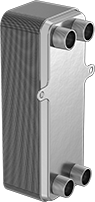
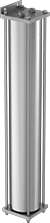
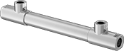
High-Efficiency Heat Exchangers
 | 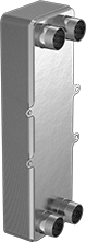 | 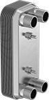 | 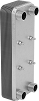 |
2 Mounting Holes | 4 Mounting Holes | 2 Mounting Studs | With Four Mounting Studs |
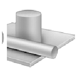
Stacked, corrugated plates maximize contact with liquid or steam flowing through these brazed plate heat exchangers for faster heat transfer than shell and tube heat exchangers. Plates are brazed in a vacuum furnace to ensure 100% sealed construction.
ASME BPVC.VIII.1 Certified Heat Exchangers—ASME BPVC VIII.1 copper-brazed heat exchangers have a Btu/hr. cooling capacity based on cooling 100 SSU oil to 125° F using 85° F water. They meet the ASME Boiler and Pressure Vessel Code (BPVC) for construction of pressure vessels.
Nickel-Brazed 316 Stainless Steel Plate—Nickel-brazed heat exchangers have a Btu/hr. cooling capacity based on cooling oil from 140° to 120° F using 70° F water.
Copper-Brazed 316 Stainless Steel Plate—Copper-brazed heat exchangers have a Btu/hr. cooling capacity based on cooling water from 120° to 100° F using 70° F water.
Overall | Mounting Hole | Mounting Stud | |||||||||||||||||||||||||||||||||||||||||||||||||||||||||||||||||||||||||||||||||||||||||||||||||
|---|---|---|---|---|---|---|---|---|---|---|---|---|---|---|---|---|---|---|---|---|---|---|---|---|---|---|---|---|---|---|---|---|---|---|---|---|---|---|---|---|---|---|---|---|---|---|---|---|---|---|---|---|---|---|---|---|---|---|---|---|---|---|---|---|---|---|---|---|---|---|---|---|---|---|---|---|---|---|---|---|---|---|---|---|---|---|---|---|---|---|---|---|---|---|---|---|---|---|---|
Heating/Cooling Cap., BTU/hr | Surface Area, ft² | Temp. Range, ° F | Pipe Size | Thread Type | Gender | Flow Cap., gpm | Max. Pressure, psi | Ht. | Wd. | Dp. | No. of | Dia. | No. of | Thread Size | Lg. | Each | |||||||||||||||||||||||||||||||||||||||||||||||||||||||||||||||||||||||||||||||||||
Heat Exchangers | |||||||||||||||||||||||||||||||||||||||||||||||||||||||||||||||||||||||||||||||||||||||||||||||||||
Nickel-Brazed 316 Stainless Steel Plate | |||||||||||||||||||||||||||||||||||||||||||||||||||||||||||||||||||||||||||||||||||||||||||||||||||
| 16,000 | 3.1 | -320 to 390 | 1 | NPT | Male | 4 | 360 | 13 3/16" | 4 7/8" | 2 3/16" | — | — | 4 | M10 | 13/16" | 3253K31 | 0000000 | ||||||||||||||||||||||||||||||||||||||||||||||||||||||||||||||||||||||||||||||||||
| 37,000 | 6.8 | -320 to 390 | 1 | NPT | Male | 9 | 360 | 13 3/16" | 4 7/8" | 3 1/16" | — | — | 4 | M10 | 13/16" | 3253K32 | 00000000 | ||||||||||||||||||||||||||||||||||||||||||||||||||||||||||||||||||||||||||||||||||
| 56,000 | 10.6 | -320 to 390 | 1 | NPT | Male | 13 | 360 | 13 3/16" | 4 7/8" | 4" | — | — | 4 | M10 | 13/16" | 3253K33 | 00000000 | ||||||||||||||||||||||||||||||||||||||||||||||||||||||||||||||||||||||||||||||||||
| 74,000 | 14.3 | -320 to 390 | 1 | NPT | Male | 18 | 360 | 13 3/16" | 4 7/8" | 4 7/8" | — | — | 4 | M10 | 13/16" | 3253K34 | 00000000 | ||||||||||||||||||||||||||||||||||||||||||||||||||||||||||||||||||||||||||||||||||
| 120,000 | 40.7 | -320 to 390 | 2 | NPT | Male | 30 | 390 | 20 15/16" | 10 11/16" | 4 1/16" | — | — | 4 | M12 | 1 3/16" | 3253K35 | 00000000 | ||||||||||||||||||||||||||||||||||||||||||||||||||||||||||||||||||||||||||||||||||
UL Listed Heat Exchangers | |||||||||||||||||||||||||||||||||||||||||||||||||||||||||||||||||||||||||||||||||||||||||||||||||||
Copper-Brazed 316 Stainless Steel Plate | |||||||||||||||||||||||||||||||||||||||||||||||||||||||||||||||||||||||||||||||||||||||||||||||||||
| 69,000 | 2.2 | -320 to 350 | 3/4 | NPT | Male | 7 | 450 | 9 1/8" | 3 1/2" | 2 5/8" | — | — | 2 | M8 | 20 mm | 35115K61 | 000000 | ||||||||||||||||||||||||||||||||||||||||||||||||||||||||||||||||||||||||||||||||||
| 80,000 | 3 | -320 to 350 | 1 | NPT | Male | 8 | 450 | 13 3/16" | 5" | 1 1/4" | — | — | 4 | M10 | 20 mm | 35115K62 | 000000 | ||||||||||||||||||||||||||||||||||||||||||||||||||||||||||||||||||||||||||||||||||
| 185,000 | 6.8 | -320 to 350 | 1 | NPT | Male | 19 | 450 | 13 3/16" | 5" | 2" | — | — | 4 | M8 | 20 mm | 35115K63 | 000000 | ||||||||||||||||||||||||||||||||||||||||||||||||||||||||||||||||||||||||||||||||||
| 390,000 | 14.3 | -320 to 350 | 1 | NPT | Male | 40 | 450 | 13 3/16" | 5" | 4" | — | — | 4 | M10 | 20 mm | 35115K64 | 000000 | ||||||||||||||||||||||||||||||||||||||||||||||||||||||||||||||||||||||||||||||||||
| 570,000 | 21.9 | -320 to 350 | 1 1/4 | NPT | Male | 58 | 450 | 13 3/16" | 5" | 5 3/4" | — | — | 4 | M8 | 20 mm | 35115K65 | 00000000 | ||||||||||||||||||||||||||||||||||||||||||||||||||||||||||||||||||||||||||||||||||
| 998,000 | 41 | -320 to 390 | 2 | NPT | Male | 120 | 450 | 20 15/16" | 10 11/16" | 3 1/8" | — | — | 4 | M12 | 30 mm | 35115K76 | 00000000 | ||||||||||||||||||||||||||||||||||||||||||||||||||||||||||||||||||||||||||||||||||
| 1,710,000 | 68.3 | -320 to 390 | 2 | NPT | Male | 120 | 450 | 20 15/16" | 10 11/16" | 4 15/16" | — | — | 4 | M12 | 30 mm | 35115K77 | 00000000 | ||||||||||||||||||||||||||||||||||||||||||||||||||||||||||||||||||||||||||||||||||
ASME BPVC.VIII.1 Certified Heat Exchangers | |||||||||||||||||||||||||||||||||||||||||||||||||||||||||||||||||||||||||||||||||||||||||||||||||||
Copper-Brazed 316 Stainless Steel Plate | |||||||||||||||||||||||||||||||||||||||||||||||||||||||||||||||||||||||||||||||||||||||||||||||||||
| 5,000 | 4.8 | -310 to 450 | 3/4 | NPT | Male | 27 | 435 | 8 7/16" | 3 3/16" | 4 7/16" | 2 | 9/32" | — | — | — | 8546T11 | 000000 | ||||||||||||||||||||||||||||||||||||||||||||||||||||||||||||||||||||||||||||||||||
| 12,000 | 7.9 | -310 to 450 | 1 | NPT | Male | 29 | 435 | 12 3/16" | 4 3/8" | 4 1/4" | 2 | 13/32" | — | — | — | 8546T12 | 000000 | ||||||||||||||||||||||||||||||||||||||||||||||||||||||||||||||||||||||||||||||||||
| 17,000 | 10.7 | -310 to 450 | 1 | NPT | Male | 37 | 435 | 12 3/16" | 4 3/8" | 5 1/4" | 2 | 13/32" | — | — | — | 8546T13 | 000000 | ||||||||||||||||||||||||||||||||||||||||||||||||||||||||||||||||||||||||||||||||||
| 50,000 | 15.6 | -310 to 450 | 1 | NPT | Male | 22 | 435 | 20 11/16" | 4 3/8" | 4 1/4" | 2 | 13/32" | — | — | — | 8546T14 | 000000 | ||||||||||||||||||||||||||||||||||||||||||||||||||||||||||||||||||||||||||||||||||
| 75,000 | 26.8 | -310 to 450 | 1 | NPT | Male | 34 | 435 | 20 11/16" | 4 3/8" | 6 3/16" | 2 | 13/32" | — | — | — | 8546T15 | 00000000 | ||||||||||||||||||||||||||||||||||||||||||||||||||||||||||||||||||||||||||||||||||
| 125,000 | 29.7 | -310 to 450 | 2 | NPT | Male | 57 | 435 | 24 5/16" | 7 1/2" | 5 3/4" | 4 | 1/2" | — | — | — | 8546T16 | 00000000 | ||||||||||||||||||||||||||||||||||||||||||||||||||||||||||||||||||||||||||||||||||
| 380,000 | 82.8 | -310 to 450 | 2 | NPT | Male | 141 | 435 | 24 5/16" | 7 1/2" | 11 1/2" | 4 | 1/2" | — | — | — | 8546T17 | 00000000 | ||||||||||||||||||||||||||||||||||||||||||||||||||||||||||||||||||||||||||||||||||
Heat Exchangers for Sampling
NPT Female Threaded Shell-Side and Tube-Side Connections
 | |
1.3 ft² Surface Area | 3.8 ft² Surface Area |
Shell-Side | Tube Side | Overall | |||||||||||||||||||||||||||||||||||||||||||||||||||||||||||||||||||||||||||||||||||||||||||||||||
|---|---|---|---|---|---|---|---|---|---|---|---|---|---|---|---|---|---|---|---|---|---|---|---|---|---|---|---|---|---|---|---|---|---|---|---|---|---|---|---|---|---|---|---|---|---|---|---|---|---|---|---|---|---|---|---|---|---|---|---|---|---|---|---|---|---|---|---|---|---|---|---|---|---|---|---|---|---|---|---|---|---|---|---|---|---|---|---|---|---|---|---|---|---|---|---|---|---|---|---|
Heating/Cooling Cap. | Surface Area, ft² | Pipe Size | Flow Cap., gpm | Max. Pressure, psi | Max. Temp., ° F | Pipe Size | Flow Cap., gpm | Max. Pressure, psi | Max. Temp., ° F | Lg. | Head Dia. | Each | |||||||||||||||||||||||||||||||||||||||||||||||||||||||||||||||||||||||||||||||||||||||
Steel Shell and Copper Tube | |||||||||||||||||||||||||||||||||||||||||||||||||||||||||||||||||||||||||||||||||||||||||||||||||||
| Not Rated | 1.3 | 1/4 | 2 | 150 | 450 | 1/4 | 4 | 300 | 400 | 17 1/4" | 3 1/2" | 3613K31 | 0000000 | ||||||||||||||||||||||||||||||||||||||||||||||||||||||||||||||||||||||||||||||||||||||
Steel Shell and 316 Stainless Steel Tube | |||||||||||||||||||||||||||||||||||||||||||||||||||||||||||||||||||||||||||||||||||||||||||||||||||
| Not Rated | 1.3 | 1/4 | 2 | 150 | 450 | 1/4 | 4 | 3,000 | 750 | 17 1/4" | 3 1/2" | 3613K41 | 000000 | ||||||||||||||||||||||||||||||||||||||||||||||||||||||||||||||||||||||||||||||||||||||
| Not Rated | 3.8 | 3/8 | 2 | 150 | 450 | 1/4 | 4 | 4,900 | 750 | 32 5/8" | — | 3613K61 | 00000000 | ||||||||||||||||||||||||||||||||||||||||||||||||||||||||||||||||||||||||||||||||||||||
High-Pressure Heat Exchangers
NPT Female Threaded Shell-Side and Tube-Side Connections
 |
316 Stainless Steel Shell—Shell is 316 stainless steel for excellent corrosion resistance.
316 Stainless Steel Tube—Tubes are 316 stainless steel for excellent corrosion resistance.
Heating/Cooling Capacity—Btu/hr. cooling capacity is based on cooling 180° F process water with 85° F water and a 10 psi pressure difference.
Temp., ° F | Shell-Side | Tube Side | Overall | ||||||||||||||||||||||||||||||||||||||||||||||||||||||||||||||||||||||||||||||||||||||||||||||||
|---|---|---|---|---|---|---|---|---|---|---|---|---|---|---|---|---|---|---|---|---|---|---|---|---|---|---|---|---|---|---|---|---|---|---|---|---|---|---|---|---|---|---|---|---|---|---|---|---|---|---|---|---|---|---|---|---|---|---|---|---|---|---|---|---|---|---|---|---|---|---|---|---|---|---|---|---|---|---|---|---|---|---|---|---|---|---|---|---|---|---|---|---|---|---|---|---|---|---|---|
Heating/Cooling Cap., BTU/hr | Surface Area, ft² | Max. Pressure for Steam, psi | Min. | Max. | Pipe Size | Flow Cap., gpm | Max. Pressure, psi | Pipe Size | Flow Cap., gpm | Max. Pressure, psi | Lg. | Head Dia. | Each | ||||||||||||||||||||||||||||||||||||||||||||||||||||||||||||||||||||||||||||||||||||||
316 Stainless Steel Shell and 316 Stainless Steel Tube | |||||||||||||||||||||||||||||||||||||||||||||||||||||||||||||||||||||||||||||||||||||||||||||||||||
| 59,000 | 0.4 | 125 | -320 | 800 | 1/4 | 4.8 | 1,000 | 3/8 | 10.9 | 1,500 | 9 3/4" | 1 1/8" | 3771K14 | 000000000 | |||||||||||||||||||||||||||||||||||||||||||||||||||||||||||||||||||||||||||||||||||||
| 65,500 | 0.61 | 125 | -320 | 800 | 1/4 | 4.4 | 1,000 | 3/8 | 9.3 | 1,500 | 13 3/4" | 1 1/8" | 3771K15 | 00000000 | |||||||||||||||||||||||||||||||||||||||||||||||||||||||||||||||||||||||||||||||||||||
| 76,500 | 0.58 | 125 | -320 | 800 | 1/4 | 4.8 | 1,000 | 3/8 | 10.1 | 1,500 | 9 3/4" | 1 1/8" | 3771K11 | 00000000 | |||||||||||||||||||||||||||||||||||||||||||||||||||||||||||||||||||||||||||||||||||||
| 90,000 | 0.89 | 125 | -320 | 800 | 1/4 | 4.4 | 1,000 | 3/8 | 8.4 | 1,500 | 13 3/4" | 1 1/8" | 3771K12 | 00000000 | |||||||||||||||||||||||||||||||||||||||||||||||||||||||||||||||||||||||||||||||||||||
| 98,000 | 1.19 | 125 | -320 | 800 | 1/4 | 4.2 | 1,000 | 3/8 | 7.3 | 1,500 | 17 3/4" | 1 1/8" | 3771K13 | 00000000 | |||||||||||||||||||||||||||||||||||||||||||||||||||||||||||||||||||||||||||||||||||||
