Filter by
System of Measurement
Fitting Connection


For Use With
Body Material
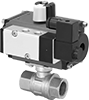
Actuation Type
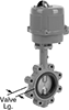
Butterfly Valve Type
Seat Material
Fitting Type
Overall Length
Maximum Pressure @ Temperature
Actuation Mechanism
Export Control Classification Number (ECCN)
DFARS Specialty Metals
Fluid Handling