About Actuated On/Off Valves
More
Matching Flow Diagrams to Replace an Air Directional Control Valve
More
Choosing an Air Directional Control Valve
More
About Hazardous Location Environmental Ratings
More
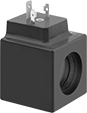
Compact Solenoid On/Off Valves for Coolant
- For Use With: Ethylene Glycol
- Seal Material: Fluoroelastomer Rubber
- Specifications Met: See table
Reduce your pipeline footprint with these low-profile valves that are about half the size of standard valves for coolant. They operate on electricity to automatically start and stop flow.
Valves are normally closed unless actuated. They don’t require a minimum pressure drop between the inlet and outlet for operation. The actuator is directly mounted to the valve body to minimize movement and reduce wear.
Metal valves are more durable than acetal valves. Flow coefficient (Cv) is the amount of water (in gallons per minute) at 60° F that will flow through a fully open valve with a difference of 1 psi between the inlet and the outlet.
| Pipe Size | Gender | Thread Type | Flow Coefficient (Cv) | Max. Pressure | Pressure Drop | Temp. Range, °F | Valve Lg. | O'all Ht. | Environmental Rating | Specifications Met | Each | |
Brass Body with DIN Connection | ||||||||||||
|---|---|---|---|---|---|---|---|---|---|---|---|---|
Normally Closed—120V AC | ||||||||||||
| 1/8 | Female | NPT | 0.21 | 72 psi @ 140° F | Zero Pressure Drop | 35° to 140° | 1 5/16" | 2 5/8" | IP67 | CE Marked | 00000000 | 000000 |
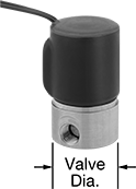
Food Industry Solenoid On/Off Valves
- For Use With: Food, Beverage
- Seal Material: Fluoroelastomer Rubber
- Specifications Met: See table
Add automated on/off control to food equipment with these valves that meet NSF/ANSI 169, which designates them as safe to use with food. They operate on electricity to automatically start and stop flow.
These valves are normally closed unless actuated. They don’t require a minimum pressure drop between the inlet and outlet for operation. Body is 430 stainless steel for good corrosion resistance. The actuator is directly mounted to the valve body to minimize movement and reduce wear.
NEMA 6 valves meet a standard for resistance to washdowns, splashing water, temporary submersion, and dust.
Flow coefficient (Cv) is the amount of water (in gallons per minute) at 60° F that will flow through a fully open valve with a difference of 1 psi between the inlet and the outlet.
Mounting Holes | ||||||||||||||||
|---|---|---|---|---|---|---|---|---|---|---|---|---|---|---|---|---|
| Pipe Size | Gender | Thread Type | Flow Coefficient (Cv) | Max. Pressure | Pressure Drop | Temp. Range, °F | Valve Dia. | O'all Ht. | Mounting Fasteners Included | No. of | Thread Size | Wire Connection Type | Environmental Rating | Specifications Met | Each | |
430 Stainless Steel Body with Hardwire Connection | ||||||||||||||||
Normally Closed—12V DC | ||||||||||||||||
| 1/8 | Female | NPT | 0.08 | 325 psi @ 325° F | Zero Pressure Drop | 0° to 325° | 1" | 2 3/8" | No | 2 | 8-32 | Wire Leads | IP68, NEMA 6 | NSF/ANSI 169 | 00000000 | 0000000 |
| 1/8 | Female | NPT | 0.16 | 175 psi @ 325° F | Zero Pressure Drop | 0° to 325° | 1" | 2 3/8" | No | 2 | 8-32 | Wire Leads | IP68, NEMA 6 | NSF/ANSI 169 | 00000000 | 000000 |
| 1/4 | Female | NPT | 0.1 | 400 psi @ 325° F | Zero Pressure Drop | 0° to 325° | 1 5/8" | 2 7/8" | No | 2 | 10-32 | Wire Leads | IP68, NEMA 6 | NSF/ANSI 169 | 00000000 | 000000 |
| 1/4 | Female | NPT | 0.16 | 250 psi @ 325° F | Zero Pressure Drop | 0° to 325° | 1 5/8" | 2 7/8" | No | 2 | 10-32 | Wire Leads | IP68, NEMA 6 | NSF/ANSI 169 | 00000000 | 000000 |
Normally Closed—24V AC | ||||||||||||||||
| 1/8 | Female | NPT | 0.08 | 470 psi @ 325° F | Zero Pressure Drop | 0° to 325° | 1" | 2 3/8" | No | 2 | 8-32 | Wire Leads | IP68, NEMA 6 | NSF/ANSI 169 | 00000000 | 000000 |
| 1/8 | Female | NPT | 0.16 | 260 psi @ 325° F | Zero Pressure Drop | 0° to 325° | 1" | 2 3/8" | No | 2 | 8-32 | Wire Leads | IP68, NEMA 6 | NSF/ANSI 169 | 00000000 | 000000 |
| 1/4 | Female | NPT | 0.1 | 400 psi @ 325° F | Zero Pressure Drop | 0° to 325° | 1 5/8" | 2 7/8" | No | 2 | 10-32 | Wire Leads | IP68, NEMA 6 | NSF/ANSI 169 | 00000000 | 000000 |
| 1/4 | Female | NPT | 0.16 | 300 psi @ 325° F | Zero Pressure Drop | 0° to 325° | 1 5/8" | 2 7/8" | No | 2 | 10-32 | Wire Leads | IP68, NEMA 6 | NSF/ANSI 169 | 00000000 | 000000 |
Normally Closed—24V DC | ||||||||||||||||
| 1/8 | Female | NPT | 0.08 | 325 psi @ 325° F | Zero Pressure Drop | 0° to 325° | 1" | 2 3/8" | No | 2 | 8-32 | Wire Leads | IP68, NEMA 6 | NSF/ANSI 169 | 00000000 | 000000 |
| 1/8 | Female | NPT | 0.16 | 175 psi @ 325° F | Zero Pressure Drop | 0° to 325° | 1" | 2 3/8" | No | 2 | 8-32 | Wire Leads | IP68, NEMA 6 | NSF/ANSI 169 | 00000000 | 000000 |
| 1/8 | Female | NPT | 0.28 | 200 psi @ 165° F | Zero Pressure Drop | 0° to 165° | 1 5/8" | 2 7/8" | No | 2 | 8-32 | Wire Leads | IP68, NEMA 6 | NSF/ANSI 169 | 0000000 | 000000 |
| 1/4 | Female | NPT | 0.1 | 400 psi @ 325° F | Zero Pressure Drop | 0° to 325° | 1 5/8" | 2 7/8" | No | 2 | 10-32 | Wire Leads | IP68, NEMA 6 | NSF/ANSI 169 | 00000000 | 000000 |
| 1/4 | Female | NPT | 0.16 | 250 psi @ 325° F | Zero Pressure Drop | 0° to 325° | 1 5/8" | 2 7/8" | No | 2 | 10-32 | Wire Leads | IP68, NEMA 6 | NSF/ANSI 169 | 00000000 | 000000 |
Normally Closed—120V AC | ||||||||||||||||
| 1/8 | Female | NPT | 0.08 | 470 psi @ 325° F | Zero Pressure Drop | 0° to 325° | 1" | 2 3/8" | No | 2 | 8-32 | Wire Leads | IP68, NEMA 6 | NSF/ANSI 169 | 00000000 | 000000 |
| 1/8 | Female | NPT | 0.16 | 260 psi @ 325° F | Zero Pressure Drop | 0° to 325° | 1" | 2 3/8" | No | 2 | 8-32 | Wire Leads | IP68, NEMA 6 | NSF/ANSI 169 | 00000000 | 000000 |
| 1/4 | Female | NPT | 0.1 | 400 psi @ 325° F | Zero Pressure Drop | 0° to 325° | 1 5/8" | 2 7/8" | No | 2 | 10-32 | Wire Leads | IP68, NEMA 6 | NSF/ANSI 169 | 00000000 | 000000 |
| 1/4 | Female | NPT | 0.16 | 300 psi @ 325° F | Zero Pressure Drop | 0° to 325° | 1 5/8" | 2 7/8" | No | 2 | 10-32 | Wire Leads | IP68, NEMA 6 | NSF/ANSI 169 | 00000000 | 000000 |
| 1/4 | Female | NPT | 0.28 | 200 psi @ 165° F | Zero Pressure Drop | 0° to 165° | 1 5/8" | 2 7/8" | No | 2 | 10-32 | Wire Leads | IP68, NEMA 6 | NSF/ANSI 169 | 0000000 | 000000 |
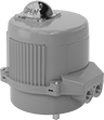
Motor-Driven Valve Actuators

Use electricity to start and stop flow to valves automatically. They adhere to standard ISO 5211 dimensions for mounting to valves. Use valve stem adapters to mount actuators to smaller ISO 5211 valve stems.
To prevent electrical burnout from excessive and unexpected loads, these actuators have a torque limiter. They also have a manual override, so you can continue to operate the actuator during power outages. These actuators have single pole, double throw (SPDT) auxiliary switches, which allow you to connect them to temperature-monitoring equipment, programmable logic controllers (PLCs), or conveyor sirens. A flow indicator on the top of the actuator shows whether the valve is open or closed. When the valve is actuated, an internal heater will automatically turn on to prevent motor damage from condensation buildup.
Fail-in-place actuators will remain in their current position if power is lost.
Fail-closed actuators have a battery that will switch the actuator to the closed position if power is lost, protecting downstream equipment from excessive pressure.
Nylon actuators resist cleaners and other chemicals better than aluminum actuators. IP and NEMA rated, they protect against dust and washdowns. IP67-rated actuators also keep out water when submerged.
Aluminum actuators stand up to impact better than nylon actuators. They are IP and NEMA rated, so they protect against dust, washdowns, and have the highest rating for submersion.
| Torque, in.-lbs. | Actuation Time, sec. | Hole Pattern | Actuator Mounting Pattern | For Stem Size, mm | Housing Material | Frequency, Hz | Wire Connection Type | Temp. Range, °F | Lg. | Wd. | Ht. | Environmental Rating | Each | |
100-240V AC—Fail in Place | ||||||||||||||
|---|---|---|---|---|---|---|---|---|---|---|---|---|---|---|
| 150 | 9 | ISO 5211 | F03, F05 | 11 | Aluminum | 50/60 | Screw Terminals | 0° to 130° | 6 1/8" | 5 3/8" | 7" | IP68, NEMA 4X | 0000000 | 0000000 |
| 530 | 9 | ISO 5211 | F05, F07 | 14 | Nylon Plastic | 50/60 | Screw Terminals | 0° to 130° | 8 7/16" | 7 1/4" | 8 7/16" | IP67, NEMA 4X | 0000000 | 000000 |
| 530 | 9 | ISO 5211 | F07, F10 | 14 | Aluminum | 50/60 | Screw Terminals | 0° to 130° | 7 3/4" | 6 15/16" | 8 5/8" | IP68, NEMA 4X | 0000000 | 000000 |
| 1,680 | 27 | ISO 5211 | F07, F10 | 17 | Nylon Plastic | 50/60 | Screw Terminals | 0° to 130° | 9 5/16" | 8 5/16" | 9 1/8" | IP67, NEMA 4X | 0000000 | 000000 |
| 1,680 | 27 | ISO 5211 | F07, F10 | 17 | Aluminum | 50/60 | Screw Terminals | 0° to 130° | 10 5/8" | 10 7/16" | 12 5/16" | IP68, NEMA 4X | 0000000 | 00000000 |
100-240V AC—Fail Closed | ||||||||||||||
| 150 | 9 | ISO 5211 | F03, F05 | 11 | Aluminum | 50/60 | Screw Terminals | 0° to 130° | 6 1/8" | 5 3/8" | 7" | IP68, NEMA 4X | 0000000 | 00000000 |
| 530 | 9 | ISO 5211 | F07, F10 | 14 | Aluminum | 50/60 | Screw Terminals | 0° to 130° | 7 3/4" | 6 15/16" | 8 5/8" | IP68, NEMA 4X | 0000000 | 00000000 |
| 1,680 | 27 | ISO 5211 | F07, F10 | 17 | Aluminum | 50/60 | Screw Terminals | 0° to 130° | 10 5/8" | 10 7/16" | 12 5/16" | IP68, NEMA 4X | 0000000 | 00000000 |
24V AC, 24V DC—Fail in Place | ||||||||||||||
| 150 | 9 | ISO 5211 | F03, F05 | 11 | Aluminum | 50/60 | Screw Terminals | 0° to 130° | 6 1/8" | 5 3/8" | 7" | IP68, NEMA 4X | 0000000 | 000000 |
| 530 | 9 | ISO 5211 | F05, F07 | 14 | Nylon Plastic | 50/60 | Screw Terminals | 0° to 130° | 8 7/16" | 7 1/4" | 8 7/16" | IP67, NEMA 4X | 0000000 | 000000 |
| 530 | 9 | ISO 5211 | F07, F10 | 14 | Aluminum | 50/60 | Screw Terminals | 0° to 130° | 7 3/4" | 6 15/16" | 8 5/8" | IP68, NEMA 4X | 0000000 | 000000 |
| 1,680 | 27 | ISO 5211 | F07, F10 | 17 | Nylon Plastic | 50/60 | Screw Terminals | 0° to 130° | 9 5/16" | 8 5/16" | 9 1/8" | IP67, NEMA 4X | 0000000 | 000000 |
| 1,680 | 27 | ISO 5211 | F07, F10 | 17 | Aluminum | 50/60 | Screw Terminals | 0° to 130° | 10 5/8" | 10 7/16" | 12 5/16" | IP68, NEMA 4X | 0000000 | 00000000 |
24V AC, 24V DC—Fail Closed | ||||||||||||||
| 150 | 9 | ISO 5211 | F03, F05 | 11 | Aluminum | 50/60 | Screw Terminals | 0° to 130° | 6 1/8" | 5 3/8" | 7" | IP68, NEMA 4X | 0000000 | 000000 |
| 530 | 9 | ISO 5211 | F07, F10 | 14 | Aluminum | 50/60 | Screw Terminals | 0° to 130° | 7 3/4" | 6 15/16" | 8 5/8" | IP68, NEMA 4X | 0000000 | 00000000 |
| 1,680 | 27 | ISO 5211 | F07, F10 | 17 | Aluminum | 50/60 | Screw Terminals | 0° to 130° | 10 5/8" | 10 7/16" | 12 5/16" | IP68, NEMA 4X | 0000000 | 00000000 |
Motor-Driven Flow-Adjustment Valve Actuators
Automatically start, stop, and adjust flow through valves. These actuators receive analog signals from a programmable logic controller (PLC) to regulate flow by controlling how far the valve opens and closes. They adhere to standard ISO 5211 dimensions for mounting to valves. Use valve stem adapters to mount actuators to smaller ISO 5211 valve stems.
To prevent electrical burnout from excessive and unexpected loads, these actuators have a torque limiter. They also have a manual override, so you can continue to operate the actuator during power outages. If power is lost, the actuator will remain in its current position. This is known as fail in place. They also have single pole, double throw (SPDT) auxiliary switches, which allow you to connect these actuators to temperature-monitoring equipment, PLCs, or conveyor sirens. A flow indicator on the top of the actuator shows whether the valve is open or closed. To prevent motor damage from condensation buildup, an internal heater will automatically turn on when the valve is actuated.
Rated IP68 and NEMA 4X, these actuators protect against dust, submersion, and washdown.
Input Signal | |||||||||||||||
|---|---|---|---|---|---|---|---|---|---|---|---|---|---|---|---|
| Torque, in.-lbs. | Actuation Time, sec. | Hole Pattern | Actuator Mounting Pattern | For Stem Size, mm | Housing Material | Frequency, Hz | Wire Connection Type | Temp. Range, °F | Current | Voltage | Lg. | Wd. | Ht. | Each | |
100-240V AC—Fail in Place | |||||||||||||||
| 150 | 9 | ISO 5211 | F03, F05 | 11 | Aluminum | 50/60 | Screw Terminals | 0° to 130° | 4mA-20mA | 0V DC-10V DC | 6 1/8" | 5 3/8" | 7" | 0000000 | 0000000 |
| 530 | 9 | ISO 5211 | F07, F10 | 14 | Aluminum | 50/60 | Screw Terminals | 0° to 130° | 4mA-20mA | 0V DC-10V DC | 7 3/4" | 6 15/16" | 8 5/8" | 0000000 | 00000000 |
| 1,680 | 27 | ISO 5211 | F07, F10 | 17 | Aluminum | 50/60 | Screw Terminals | 0° to 130° | 4mA-20mA | 0V DC-10V DC | 10 5/8" | 10 7/16" | 12 5/16" | 0000000 | 00000000 |
24V AC, 24V DC—Fail in Place | |||||||||||||||
| 150 | 9 | ISO 5211 | F03, F05 | 11 | Aluminum | 50/60 | Screw Terminals | 0° to 130° | 4mA-20mA | 0V DC-10V DC | 6 1/8" | 5 3/8" | 7" | 0000000 | 000000 |
| 530 | 9 | ISO 5211 | F07, F10 | 14 | Aluminum | 50/60 | Screw Terminals | 0° to 130° | 4mA-20mA | 0V DC-10V DC | 7 3/4" | 6 15/16" | 8 5/8" | 0000000 | 00000000 |
| 1,680 | 27 | ISO 5211 | F07, F10 | 17 | Aluminum | 50/60 | Screw Terminals | 0° to 130° | 4mA-20mA | 0V DC-10V DC | 10 5/8" | 10 7/16" | 12 5/16" | 0000000 | 00000000 |
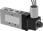
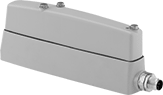
Hazardous Location Electrically Operated Air Directional Control Valves
These valves are rated for environments where hazardous material is present. Often used to extend and then retract a cylinder at different speeds, they create two actions and have two exhaust ports, which allows you to control the speed of each action by attaching a flow control valve to each exhaust port. They direct airflow from the inlet to your equipment and exhaust return airflow to create motion. Apply voltage to the electrical connection to actuate. Return actuation is by spring, so they go back to their original position when voltage is removed. Also known as 4-way valves.
5/3 (closed center) valves close all ports in the off position to stop equipment in a locked position with air pressure holding it in place.
Flow coefficient (Cv) is a measurement that indicates how much airflow can pass through a valve.
Hazardous location environmental ratings indicate whether manufacturers have included safety features in products to facilitate their safe use in a hazardous environment. Before selecting a product for a hazardous location, ensure it is rated for your environment.
Overall | |||||||||||||||
|---|---|---|---|---|---|---|---|---|---|---|---|---|---|---|---|
| No. of Flow Ports | Inlet Size | Outlet Size | Max. Flow Rate, scfm @ 100 psi | Flow Coefficient (Cv) | Pressure Range, psi | Vacuum Rating, in. of Hg | Environmental Rating | Voltage | Wire Connection Type | Lg. | Wd. | Ht. | Mounting Fasteners Included | Each | |
5/2 Flow Pattern | |||||||||||||||
Single Solenoid | |||||||||||||||
| 5 | 1/4 NPT | 1/4 NPT | 65.34 | 1.7 | 14-145 | 28 | NEC Class I Divisions 1, 2 Groups A, B, C, D NEC Class II Divisions 1, 2 Groups E, F, G NEMA 3S NEMA 6P NEMA 7 NEMA 9 | 24V DC | Wire Leads | 6" | 1" | 2 7/8" | No | 0000000 | 0000000 |
| 5 | 1/4 NPT | 1/4 NPT | 65.34 | 1.7 | 14-145 | 28 | NEC Class I Divisions 1, 2 Groups A, B, C, D NEC Class II Divisions 1, 2 Groups E, F, G NEMA 3S NEMA 6P NEMA 7 NEMA 9 | 120V AC | Wire Leads | 6" | 1" | 2 7/8" | No | 0000000 | 000000 |
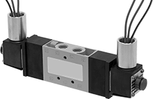
5/3 (Closed Center) Flow Pattern | |||||||||||||||
Double Solenoid | |||||||||||||||
| 5 | 1/4 NPT | 1/4 NPT | 65.34 | 1.7 | 14-145 | 28 | NEC Class I Divisions 1, 2 Groups A, B, C, D NEC Class II Divisions 1, 2 Groups E, F, G NEMA 3S NEMA 6P NEMA 7 NEMA 9 | 24V DC | Wire Leads | 9 3/8" | 1" | 2 7/8" | No | 0000000 | 000000 |
| 5 | 1/4 NPT | 1/4 NPT | 65.34 | 1.7 | 14-145 | 28 | NEC Class I Divisions 1, 2 Groups A, B, C, D NEC Class II Divisions 1, 2 Groups E, F, G NEMA 3S NEMA 6P NEMA 7 NEMA 9 | 120V AC | Wire Leads | 9 3/8" | 1" | 2 7/8" | No | 0000000 | 000000 |
| Body Material | Each | |
| Aluminum | 00000000 | 000000 |
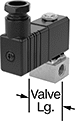
Washdown-Resistant Electrically Operated Air Directional Control Valves
3-way valves create one action, such as extending a cylinder. 4-way valves create two actions, such as extending and then retracting a double-acting cylinder. 5/3 (closed center) valves close all ports in the off position to stop equipment in a locked position with air pressure holding it in place. Valves with spring return actuation go back to their original position when voltage is removed. Valves with electric (solenoid) return actuation go back to their original position when voltage moves from the first solenoid to the second solenoid. Valves with two exhaust ports allow you to independently control the speed of two different actions. Connect a flow control valve to each exhaust port. Flow coefficient (Cv) is a measurement that indicates how much airflow can pass through a valve.
O'all | |||||||||||||
|---|---|---|---|---|---|---|---|---|---|---|---|---|---|
| Air Directional Control Valve Type | Flow Pattern | No. of Flow Ports | No. of Exhaust Ports | Max. Flow Rate, scfm @ 100 psi | Flow Coefficient (Cv) | Pressure Range, psi | Vacuum Rating, in. of Hg | Voltage | Lg. | Wd. | Ht. | Each | |
Single Solenoid—Spring Return Actuation | |||||||||||||
| 3-Way | 3/2 | 3 | 1 | 25.11 | 0.711 | -13 to 145 | 26.5 | 24V DC | 190.5 mm | 34.9 mm | 68.58 mm | 0000000 | 0000000 |
| 4-Way | 5/2 | 5 | 2 | 25.11 | 0.711 | -13 to 145 | 26.5 | 24V DC | 190.5 mm | 34.9 mm | 68.58 mm | 0000000 | 000000 |
| 4-Way | 5/3 (Closed Center) | 5 | 2 | 25.11 | 0.711 | -13 to 145 | 26.5 | 24V DC | 190.5 mm | 34.9 mm | 68.58 mm | 0000000 | 000000 |
Double Solenoid—Electric (Solenoid) Return Actuation | |||||||||||||
| 4-Way | 5/2 | 5 | 2 | 25.11 | 0.711 | -13 to 145 | 26.5 | 24V DC | 190.5 mm | 34.9 mm | 68.58 mm | 0000000 | 000000 |
O'all | |||||||||||||||
|---|---|---|---|---|---|---|---|---|---|---|---|---|---|---|---|
| Air Directional Control Valve Type | Flow Pattern | No. of Flow Ports | No. of Exhaust Ports | For Inlet Tube OD | For Outlet Tube OD | Max. Flow Rate, scfm @ 100 psi | Flow Coefficient (Cv) | Pressure Range, psi | Vacuum Rating, in. of Hg | Voltage | Lg. | Wd. | Ht. | Each | |
SingleSolenoid—Spring Return Actuation | |||||||||||||||
| 3-Way | 3/2 | 3 | 1 | 8 mm | 8 mm | 25.11 | 0.711 | -13 to 145 | 26.5 | 24V DC | 190.5 mm | 34.9 mm | 76.2 mm | 0000000 | 0000000 |
| 4-Way | 5/2 | 5 | 2 | 8 mm | 8 mm | 25.11 | 0.711 | -13 to 145 | 26.5 | 24V DC | 190.5 mm | 34.9 mm | 76.2 mm | 0000000 | 000000 |
| 4-Way | 5/3 (Closed Center) | 5 | 2 | 8 mm | 8 mm | 25.11 | 0.711 | -13 to 145 | 26.5 | 24V DC | 190.5 mm | 34.9 mm | 76.2 mm | 0000000 | 000000 |
DoubleSolenoid—Electric (Solenoid) Return Actuation | |||||||||||||||
| 4-Way | 5/2 | 5 | 2 | 8 mm | 8 mm | 25.11 | 0.711 | -13 to 145 | 26.5 | 24V DC | 190.5 mm | 34.9 mm | 76.2 mm | 0000000 | 000000 |
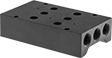
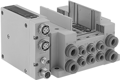
Modular Air Directional Control Valves with Air and Electrical Manifolds
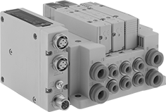
Mix and match valve styles on one manifold to meet your control needs. Mount multiple valves to a manifold to reduce piping requirements and create multiple actions from a single pressure input. Add or remove valves as your needs change.
Manifolds connect multiple valves to a common input pressure source and exhaust port.
IP67 rated manifolds are dust tight and protected from temporary submersion.
Number of Ports | Overall | |||||||||||||||
|---|---|---|---|---|---|---|---|---|---|---|---|---|---|---|---|---|
| No. of Stations | No. of Flow Ports | Inlet | Outlet | Exhaust | For Inlet Tube OD | For Outlet Tube OD | Exhaust Connection Type | Voltage | Lg. | Wd. | Ht. | Mount Type | For DIN Rail Size | Mounting Fasteners Included | Each | |
Push-to-Connect Female Inlet × Push-to-Connect Female Outlet | ||||||||||||||||
M12 Plug (IP67) | ||||||||||||||||
| 2 | 8 | 2 | 4 | 2 | 3/8" | 1/4" | Push to Connect | 24V DC | 4 3/4" | 4 1/2" | 3" | Screw In, DIN Rail | 35 mm | Yes | 000000 | 0000000 |
| 4 | 12 | 2 | 8 | 2 | 3/8" | 1/4" | Push to Connect | 24V DC | 6" | 4 1/2" | 3" | Screw In, DIN Rail | 35 mm | Yes | 00000000 | 00000000 |
| 6 | 16 | 2 | 12 | 2 | 3/8" | 1/4" | Push to Connect | 24V DC | 7 1/4" | 4 1/2" | 3" | Screw In, DIN Rail | 35 mm | Yes | 00000000 | 00000000 |
| 8 | 20 | 2 | 16 | 2 | 3/8" | 1/4" | Push to Connect | 24V DC | 8 1/2" | 4 1/2" | 3" | Screw In, DIN Rail | 35 mm | Yes | 00000000 | 00000000 |
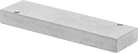
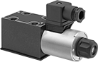
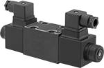
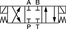
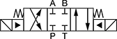
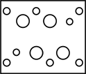
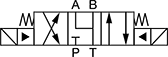
Solenoid-Operated Directional-Control Block-Mount Hydraulic Valves
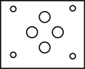
Direct flow with an electronic signal. Use screws to attach to an NFPA valve-mounting block (each component sold separately).
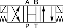
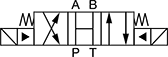
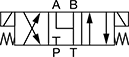
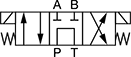
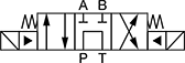
In NFPA diagrams, P represents the pressure source, T represents the tank, and A and B represent work ports.


Valves | Screws | |||||||||
|---|---|---|---|---|---|---|---|---|---|---|
| NFPA Mounting Pattern | ISO Trade Size | Max. Flow Rate, gpm | Max. Pressure, psi | Choose a Voltage | Each | Pkg. Qty. | Pkg. | |||
Default Position: Closed | ||||||||||
| 3 | D03 | 3 | 20 | 5,000 | 0000000 | 0000000 | 4 | 0000000 | 00000 | |
| 4 | D08 | 8 | 160 | 5,000 | 00000000 | 00000000 | 6 | 0000000 | 00000 | |
Default Position: Open | ||||||||||
| 5 | D03 | 3 | 20 | 5,000 | 0000000 | 000000 | 4 | 0000000 | 0000 | |
| 6 | D08 | 8 | 160 | 5,000 | 00000000 | 00000000 | 6 | 0000000 | 00000 | |
Default Position: P Closed, A and B Open to T | ||||||||||
| 7 | D03 | 3 | 10 | 5,000 | 0000000 | 000000 | 4 | 0000000 | 0000 | |
| 8 | D08 | 8 | 160 | 5,000 | 00000000 | 00000000 | 6 | 0000000 | 00000 | |
Default Position: P Open to T, A and B Closed | ||||||||||
| 9 | D03 | 3 | 15 | 5,000 | 0000000 | 000000 | 4 | 0000000 | 0000 | |
| 10 | D08 | 8 | 80 | 5,000 | 00000000 | 00000000 | 6 | 0000000 | 00000 | |