


About Actuated On/Off Valves
More
About Gradual On/Off Valves
More
About On/Off Valves
More
Flanged On/Off Valves
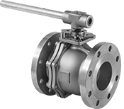
Bolt these valves to ANSI flanges. Their lockable lever handle can be fixed in place using a padlock (not included). All have four mounting holes to install an actuator, so you can convert them from manual to automatic valves.
Steel valves stand up to corrosion better than cast iron valves. 316 stainless steel valves are more corrosion resistant than cast iron and steel valves.
Full-port valves do not restrict flow. Standard-port valves slightly restrict flow.
Pressure class 150 valves are standard and work for most low-pressure applications.
Flow coefficient (Cv) is the amount of water (in gallons per minute) at 60° F that will flow through a fully open valve with a difference of 1 psi between the inlet and the outlet.
![]() For technical drawings and 3-D models, click on a part number.
For technical drawings and 3-D models, click on a part number.
- Valve Type: Ball
- For Use With: Air, Oil, Steam, Water
- Seal Material: PTFE Plastic
- Specifications Met: ANSI/ASME B16.10, ANSI/ASME B16.5, MSS-SP-72
Bolts | |||||||||||||
|---|---|---|---|---|---|---|---|---|---|---|---|---|---|
| Pipe Size | Pressure Class | Flange OD | Circle Dia. | No. of Holes | Hole Size | Included | Flow Coefficient (Cv) | Max. Pressure | Max. Steam Pressure | Temp. Range, °F | End-to-End Lg. | Each | |
Flanged × Flanged with Full Port | |||||||||||||
| 6 | 125 | 11" | 9 1/2" | 8 | 0.88" | No | 5,470 | 200 psi @ 150° F | 125 psi @ 215° F | -20° to 350° | 10 1/2" | 0000000 | 000000000 |
- Valve Type: Ball
- For Use With: Air, Oil, Steam, Water
- Seal Material: PTFE Plastic
- Specifications Met: ANSI/ASME B16.10, ANSI/ASME B16.5
Bolts | ||||||||||||||
|---|---|---|---|---|---|---|---|---|---|---|---|---|---|---|
| Pipe Size | Pressure Class | Flange OD | Circle Dia. | No. of Holes | Hole Size | Included | Flow Coefficient (Cv) | Max. Pressure | Max. Steam Pressure | Temp. Range, °F | Vacuum Rating, in. of Hg | End-to-End Lg. | Each | |
Flanged × Flanged with Full Port | ||||||||||||||
| 6 | 150 | 11" | 9 1/2" | 8 | 0.88" | No | 5,070 | 275 psi @ 100° F | 100 psi @ 365° F | 0° to 500° | 28 | 15 1/2" | 000000000 | 000000000 |
- Valve Type: Ball
- For Use With: Air, Oil, Steam, Water
- Seal Material: PTFE Plastic
- Specifications Met: ANSI/ASME B16.10, ANSI/ASME B16.34, ANSI/ASME B16.5
Bolts | ||||||||||||||
|---|---|---|---|---|---|---|---|---|---|---|---|---|---|---|
| Pipe Size | Pressure Class | Flange OD | Circle Dia. | No. of Holes | Hole Size | Included | Flow Coefficient (Cv) | Max. Pressure | Max. Steam Pressure | Temp. Range, °F | Vacuum Rating, in. of Hg | End-to-End Lg. | Each | |
Flanged × Flanged with Full Port | ||||||||||||||
| 6 | 150 | 11" | 9 1/2" | 8 | 0.88" | No | 5,070 | 275 psi @ 100° F | 100 psi @ 365° F | 0° to 500° | 28 | 15 1/2" | 000000000 | 000000000 |
Flanged × Flanged with Standard Port | ||||||||||||||
| 6 | 150 | 11" | 9 1/2" | 8 | 0.88" | No | 1,020 | 275 psi @ 100° F | 200 psi @ 365° F | 0° to 450° | 28 | 10 1/2" | 00000000 | 00000000 |
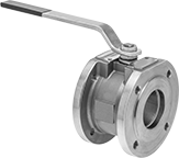
Compact Flanged On/Off Valves
- Valve Type: Ball
- For Use With: Air, Argon, Helium, Krypton, Neon, Oil, Steam, Water, Xenon
- Seal Material: PTFE Plastic
- Specifications Met: ASME B16.34, ASME B16.5, ASME B31.1
Also known as wafer ball valves, these combine the slim body of a butterfly valve with the high flow rates of a flanged ball valve. Bolt these valves to ANSI flanges—they meet ASME standards for dimensions, material, and pressure-temperature rating. They are full port, so they do not restrict flow.
316 stainless steel valves are more corrosion resistant than steel valves.
Flow coefficient (Cv) is the amount of water (in gallons per minute) at 60° F that will flow through a fully open valve with a difference of 1 psi between the inlet and the outlet.
![]() For technical drawings and 3-D models, click on a part number.
For technical drawings and 3-D models, click on a part number.
Bolts | |||||||||||||||
|---|---|---|---|---|---|---|---|---|---|---|---|---|---|---|---|
| Pipe Size | Pressure Class | Flange OD | Circle Dia. | No. of Holes | Hole Thread Size | Included | Flow Coefficient (Cv) | Max. Pressure | Max. Steam Pressure | Temperature Range, °F | Vacuum Rating, in. of Hg | End-to-End Lg. | Actuator Mounting Hole Thread Size | Each | |
Steel Body | |||||||||||||||
Flanged × Flanged | |||||||||||||||
| 6 | 150 | 11" | 9 1/2" | 8 | 3/4"-10 | No | 4,247.5 | 285 psi @ 100° F | 50 psi @ 295° F | 0° to 365° | 28 | 9 1/8" | M12 | 00000000 | 000000000 |
316 Stainless Steel Body | |||||||||||||||
Flanged × Flanged | |||||||||||||||
| 6 | 150 | 11" | 9 1/2" | 8 | 3/4"-10 | No | 4,247.5 | 275 psi @ 100° F | 50 psi @ 295° F | 0° to 365° | 28 | 9 1/8" | M12 | 00000000 | 00000000 |
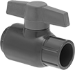
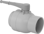
Socket-Connect On/Off Valves for Drinking Water
- Valve Type: Ball
- For Use With: Drinking Water
- Seal Material: EPDM Rubber
- Specifications Met: NSF/ANSI 61
Insert unthreaded pipe into the socket ends and bond with primer and cement to create a permanent, leak-tight connection. These valves meet NSF/ANSI 61, which means they’re safe to use with drinking water systems. They are full port, so they do not restrict flow.
PVC valves are made of the standard material used in most drinking water systems. CPVC valves resist heat better than PVC valves, so they’re better for water systems connected to a heater.
T-handles resist accidental movement when snagged or bumped. Lever handles are easy to open and close—they give you the most leverage of any handle type.
Flow coefficient (Cv) is the amount of water (in gallons per minute) at 60° F that will flow through a fully open valve with a difference of 1 psi between the inlet and the outlet.
![]() For technical drawings and 3-D models, click on a part number.
For technical drawings and 3-D models, click on a part number.
| Pipe Size | For Pipe Schedule | Flow Coefficient (Cv) | Max. Pressure | Temperature Range, °F | Vacuum Rating, in. of Hg | End-to-End Lg. | Color | Each | |
PVC Plastic Body with T-Handle | |||||||||
|---|---|---|---|---|---|---|---|---|---|
Socket Connect × Socket Connect | |||||||||
| 6 | 40, 80 | 7,942 | 150 psi @ 70° F | 40° to 140° | 26 | 14 1/4" | Dark Gray | 0000000 | 0000000 |
PVC Plastic Body with Lever Handle | |||||||||
Socket Connect × Socket Connect | |||||||||
| 6 | 40, 80 | 7,942 | 150 psi @ 70° F | 40° to 140° | 26 | 14 1/8" | White | 00000000 | 000000 |
CPVC Plastic Body with T-Handle | |||||||||
Socket Connect × Socket Connect | |||||||||
| 6 | 40, 80 | 7,942 | 150 psi @ 70° F | 40° to 200° | 26 | 14 3/16" | Light Gray | 00000000 | 00000000 |
CPVC Plastic Body with Lever Handle | |||||||||
Socket Connect × Socket Connect | |||||||||
| 6 | 40, 80 | 7,942 | 150 psi @ 70° F | 40° to 200° | 26 | 14 1/8" | Light Gray | 00000000 | 00000000 |
Threaded Gradual On/Off Valves
Also known as gate valves, these valves gradually open and close to prevent system damage from suddenly starting and stopping flow.
Valves with a pull handle open and close faster than valves with a wheel handle. Also known as slide valves, they’re often used to control flow in air conditioning and ventilation systems.
Valves with a rising stem lift the handle as they open and lower it as they close. At a glance, you can see if flow is on or off. The stem is isolated from what’s flowing through your line, giving these valves a longer lifespan than valves with a nonrising stem.
Flow coefficient (Cv) is the amount of water (in gallons per minute) at 60° F that will flow through a fully open valve with a difference of 1 psi between the inlet and the outlet.
- Valve Type: Gate
- For Use With: Oil, Air, Argon, Helium, Krypton, Neon, Xenon
O'all | |||||||||
|---|---|---|---|---|---|---|---|---|---|
| Pipe Size | Flow Coefficient (Cv) | Max. Pressure | Temp. Range, °F | Stem Housing Connection Style | End-to-End Lg. | Ht. | Lg. | Each | |
NPT Female | |||||||||
| 6 | 2,150 | 5 psi @ 1000° F | -40° to 1000° | Flanged | 3 13/16" | 18 5/8" | 8" | 0000000 | 0000000 |
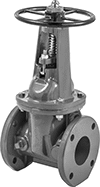
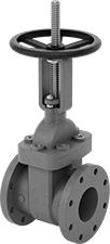
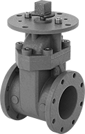
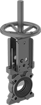
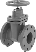
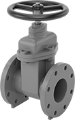
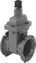
Flanged Gradual On/Off Valves
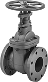
Nonrising Stem, and
Eight Bolt Holes
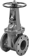
Rising Stem, and
Eight Bolt Holes
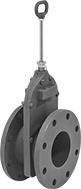
Rising Stem, and
Eight Bolt Holes
Easier to install and remove than threaded or weld-on valves, these valves bolt to flanges. They’re often used in lines requiring frequent cleaning and maintenance, such as those for slurries. They open and close gradually, preventing system damage from sudden starts and stops in flow. Also known as gate valves.
Valves with a wheel handle open and close with multiple turns, providing more controlled, shock-resistant flow than valves with a pull handle. Valves with a pull handle, also known as slide valves, open and close faster than valves with a wheel handle. They’re often used as blast gates for precise flow control in low-pressure air conditioning and ventilation systems.
Valves with a nonrising stem keep the handle in the same position whether they’re open or closed. They're often used in low-clearance locations. Valves with a rising stem lift the handle as they open and lower it as they close. At a glance, you can see if flow is on or off. The stem is isolated from what’s flowing through your line, giving these valves a longer lifespan than valves with a nonrising stem. This makes them good for critical lines and lines that need to be opened and closed frequently.
Cast iron valves are stronger than steel valves but more brittle than steel, ductile iron, and stainless steel valves. Steel valves resist impact better than cast iron valves. Ductile iron valves are stronger and more durable than cast iron valves, handling greater pressure changes without cracking. 316 stainless steel valves have the best corrosion resistance.
Flow coefficient (Cv) is the amount of water (in gallons per minute) at 60° F that will flow through a fully open valve with a difference of 1 psi between the inlet and the outlet.
- Valve Type: Gate
- For Use With: Water, Oil, Steam
- Specifications Met: ASME B16.10, MSS-SP-70
O'all | |||||||||||||||
|---|---|---|---|---|---|---|---|---|---|---|---|---|---|---|---|
| Pipe Size | Pressure Class | Flange OD | Bolt Circle Dia. | No. of Bolt Holes | Bolt Hole Dia. | Bolts Included | Flow Coefficient (Cv) | Max. Pressure | Max. Steam Pressure | Temp. Range, °F | End-to-End Lg. | Ht. | Lg. | Each | |
Flanged Stem Housing | |||||||||||||||
| 6 | 125 | 11" | 9 1/2" | 8 | 7/8" | No | 2,250 | 200 psi @ 150° F | 125 psi @ 350° F | -20° to 450° | 10 1/2" | 26 1/2" | 10 1/2" | 00000000 | 000000000 |
- Valve Type: Gate
- For Use With: Water, Oil, Air, Steam
O'all | |||||||||||||||
|---|---|---|---|---|---|---|---|---|---|---|---|---|---|---|---|
| Pipe Size | Pressure Class | Flange OD | Bolt Circle Dia. | No. of Bolt Holes | Bolt Hole Dia. | Bolts Included | Flow Coefficient (Cv) | Max. Pressure | Max. Steam Pressure | Temp. Range, °F | End-to-End Lg. | Ht. | Lg. | Each | |
Flanged Stem Housing | |||||||||||||||
| 6 | 125 | 11" | 9 1/2" | 8 | 7/8" | No | 2,250 | 200 psi @ 150° F | 125 psi @ 350° F | -20° to 450° | 10 1/2" | 32 1/8" | 10" | 0000000 | 000000000 |
- Valve Type: Gate
- For Use With: See table
- Specifications Met: See table
O'all | |||||||||||||||||
|---|---|---|---|---|---|---|---|---|---|---|---|---|---|---|---|---|---|
| Pipe Size | Pressure Class | Flange OD | Bolt Circle Dia. | No. of Bolt Holes | Bolt Hole Dia. | Bolts Included | Flow Coefficient (Cv) | Max. Pressure | Max. Steam Pressure | Temp. Range, °F | End-to-End Lg. | Ht. | Lg. | For Use With | Specifications Met | Each | |
Flanged Stem Housing | |||||||||||||||||
| 6 | 150 | 11" | 9 1/2" | 8 | 3/4" | No | 3,390 | 285 psi @ 100° F | 200 psi @ 350° F | -20° to 800° | 10 1/2" | 28 7/8" | 11 13/16" | Water, Air, Steam | American Petroleum Institute Standard 600, ASME B16.34 | 000000000 | 000000000 |
- Valve Type: Gate
- For Use With: Water, Oil, Steam
- Specifications Met: MSS-SP-128
O'all | |||||||||||||||
|---|---|---|---|---|---|---|---|---|---|---|---|---|---|---|---|
| Pipe Size | Pressure Class | Flange OD | Bolt Circle Dia. | No. of Bolt Holes | Bolt Hole Dia. | Bolts Included | Flow Coefficient (Cv) | Max. Pressure | Max. Steam Pressure | Temp. Range, °F | End-to-End Lg. | Ht. | Lg. | Each | |
Flanged Stem Housing | |||||||||||||||
| 6 | 150 | 11" | 9 1/2" | 8 | 3/4" | No | 2,250 | 285 psi @ 100° F | 150 psi @ 350° F | -20° to 450° | 10 1/2" | 26 1/2" | 12" | 0000000 | 000000000 |
- Valve Type: Gate
- For Use With: Water, Oil, Air, Steam
- Specifications Met: American Petroleum Institute Standard 603, ASME B16.34
O'all | ||||||||||||||||
|---|---|---|---|---|---|---|---|---|---|---|---|---|---|---|---|---|
| Pipe Size | Pressure Class | Flange OD | Bolt Circle Dia. | No. of Bolt Holes | Bolt Hole Dia. | Bolts Included | Flow Coefficient (Cv) | Max. Pressure | Max. Steam Pressure | Temp. Range, °F | Packing Material | End-to-End Lg. | Ht. | Lg. | Each | |
Flanged Stem Housing | ||||||||||||||||
| 6 | 150 | 11" | 9 1/2" | 8 | 7/8" | No | 4,150 | 275 psi @ 100° F | 195 psi @ 350° F | -20° to 800° | Graphite | 10 1/2" | 34 3/4" | 11 13/16" | 000000000 | 000000000 |
- Valve Type: Gate
- For Use With: Oil, Air
O'all | ||||||||||||||
|---|---|---|---|---|---|---|---|---|---|---|---|---|---|---|
| Pipe Size | Pressure Class | Flange OD | Bolt Circle Dia. | No. of Bolt Holes | Bolt Hole Dia. | Bolts Included | Flow Coefficient (Cv) | Max. Pressure | Temp. Range, °F | End-to-End Lg. | Ht. | Lg. | Each | |
Flanged Stem Housing | ||||||||||||||
| 6 | 125 | 11" | 9 1/2" | 8 | 7/8" | No | 2,150 | 5 psi @ 1000° F | -40° to 1000° | 5 3/4" | 20" | 8" | 0000000 | 000000000 |
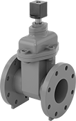
FM-Approved Flanged Gradual On/Off Valves
FM-approved, these valves are often used to isolate sections of your facility’s water supply for fire suppression and protection. They bolt to flanges for easier installation and removal than threaded or weld-on valves. This makes them a great choice if you have to clean and maintain your line frequently. Also known as gate valves, they open and close gradually to prevent sudden starts and stops of flow that could damage your system. Epoxy coated, these valves resist corrosion. They’re bright red, so they’re easy to identify as fire valves.
Their rubber-coated gate, also known as a resilient wedge, compresses against the valve for a long-lasting, leakproof seal. It seals tightly even if you install these valves vertically, or if there’s low back pressure. For easy disassembly during maintenance, they have a flanged stem housing that bolts in place. However, the housing makes these valves heavier and larger than valves with a threaded or welded stem housing.
Valves with a wheel handle open and close with multiple turns for controlled, shock-resistant flow. Wrench-operated valves are the best choice for hard-to-reach locations, such as underground or inside a manhole. Operate them from a distance with a valve wrench. You can also open and close them with a fire indicator post.
Valves with a nonrising stem keep the handle in the same position whether they’re open or closed. They're often used underground and in low-clearance locations. Valves with a rising stem lift the handle as they open and lower it as they close. At a glance, you can see if flow is on or off. The stem is isolated from what’s flowing through your line, giving these valves a longer lifespan than valves with a nonrising stem. This makes them good for critical lines and lines that need to be opened and closed frequently.
Ductile iron valves are stronger and more durable than cast iron valves. They’ll handle greater pressure changes without cracking.
Flow coefficient (Cv) is the amount of water (in gallons per minute) at 60° F that will flow through a fully open valve with a difference of 1 psi between the inlet and the outlet.
- Valve Type: Gate
- For Use With: Air, Water
- Specifications Met: ASME B16.10, ASTM A126 Class B, AWWA C509, FM Approved, MSS-SP-70, UL Listed
O'all | |||||||||||||
|---|---|---|---|---|---|---|---|---|---|---|---|---|---|
| Pipe Size | Pressure Class | Flange OD | Bolt Circle Dia. | No. of Bolt Holes | Bolt Hole Dia. | Bolts Included | Max. Pressure | Temp. Range, °F | End-to-End Lg. | Ht. | Lg. | Each | |
Flanged Stem Housing | |||||||||||||
| 6 | 125 | 11" | 9 1/2" | 8 | 7/8" | No | 200 psi @ 140° F | 35° to 140° | 10 1/2" | 29 1/4" | 10 1/2" | 00000000 | 000000000 |
- Valve Type: Gate
- For Use With: Air, Water
- Specifications Met: AWWA C515, FM Approved, UL Listed
O'all | |||||||||||||
|---|---|---|---|---|---|---|---|---|---|---|---|---|---|
| Pipe Size | Flange OD | Bolt Circle Dia. | No. of Bolt Holes | Bolt Hole Dia. | Bolts Included | Flow Coefficient (Cv) | Max. Pressure | Temp. Range, °F | End-to-End Lg. | Ht. | Lg. | Each | |
Flanged Stem Housing | |||||||||||||
| 6 | 11" | 9 1/2" | 8 | 7/8" | No | 423 | 300 psi @ 100° F | 35° to 170° | 10 1/2" | 35 1/4" | 12" | 0000000 | 0000000 |
- Valve Type: Gate
- For Use With: Drinking Water, Water
- Specifications Met: FM Approved, NSF/ANSI 61, UL Listed
O'all | |||||||||||||||||
|---|---|---|---|---|---|---|---|---|---|---|---|---|---|---|---|---|---|
| Pipe Size | Pressure Class | Flange OD | Bolt Circle Dia. | No. of Bolt Holes | Bolt Hole Dia. | Bolts Included | Flow Coefficient (Cv) | Max. Pressure | Temp. Range, °F | End-to-End Lg. | Ht. | Lg. | Drive Style | Drive Size | Features | Each | |
Flanged Stem Housing | |||||||||||||||||
| 6 | 125 | 11" | 9 1/2" | 8 | 7/8" | No | 2,250 | 300 psi @ 100° F | 35° to 140° | 10 1/2" | 22 1/2" | 10 1/2" | External Square | 2" | Indicator Post Mounting Flange | 0000000 | 000000000 |
Flanged Gradual On/Off Valves for Thick Liquids and Dry Materials
- Valve Type: Gate
- For Use With: Air, Argon, Deionized Water, Ethanol, Ethylene Glycol, Helium, Isopropyl Alcohol, Krypton, Methanol, Neon, Nitrogen, Salt Water, Soap Solutions, Water, Xenon
These valves have a sharp gate that slices through thick slurries, wastewater, dry bulk solids, and other materials that would clog other gradual on/off valves. They bolt to flanges and gradually open and close to prevent system damage from suddenly starting and stopping flow. The wheel handle opens and closes the valve with multiple turns, providing controlled, shock-resistant flow. The rising stem lifts as the valve opens and lowers as the valve closes to provide a visual indication of whether flow is on or off. The stem is isolated from the process media for a long service life.
![]() For technical drawings and 3-D models, click on a part number.
For technical drawings and 3-D models, click on a part number.
O'all | |||||||||||||
|---|---|---|---|---|---|---|---|---|---|---|---|---|---|
| Pipe Size | Flange OD | Bolt Hole Dia. | Bolt Circle Dia. | No. of Bolt Holes | Bolts Included | Max. Pressure | Temp. Range, °F | End-to-End Lg. | Ht. | Lg. | Stem Type | Each | |
Ductile Iron Body—316 Stainless Steel Gate | |||||||||||||
| 6 | 11" | 3/4" | 9 1/2" | 8 | No | 150 psi @ 248° F | -22° to 248° | 2 1/2" | 34 7/16" | 9 3/8" | Rising | 0000000 | 000000000 |
Tight-Seal Flanged Gradual On/Off Valves
A rubber-coated gate, also known as a resilient wedge, compresses against the valve seat to give these valves a tight, leakproof seal. They shut tight even when they’re installed vertically, have low back pressure, or the liquid contains solids and debris. Often called gate valves, they open and close gradually to prevent sudden starts and stops that can damage your system. Since they bolt onto flanges, they’re easier to install and remove than threaded and weld-on valves. This makes them a good choice for lines that need frequent cleaning and maintenance. You can use them in lines for water supply, reclamation, and wastewater treatment—they meet AWWA (American Water Works Association) specifications. To protect against corrosion, the body is coated with epoxy.
The stem is nonrising, so it stays in the same position whether the valve is open or closed. They’re often used in low-clearance spots. Their flanged stem housing bolts in place to make them easy to take apart for repairs. However, the flanged stem housing makes these valves heavier and larger than valves with threaded or welded stem housings.
Wrench-operated valves work well in hard-to-reach places, such as underground or the bottom of manholes, since you can turn the flow on or off from a distance. Open and close them with T-handle valve wrenches.
Ductile iron valves are stronger and more durable than cast iron valves, handling greater pressure changes without cracking.
Flow coefficient (Cv) is the amount of water (in gallons per minute) at 60° F that will flow through a fully open valve with a difference of 1 psi between the inlet and the outlet.
![]() For technical drawings and 3-D models, click on a part number.
For technical drawings and 3-D models, click on a part number.
- Valve Type: Gate
- For Use With: Water, Air
- Specifications Met: ASME B16.10, ASTM A126 Class B, AWWA C509, MSS-SP-70
O'all | ||||||||||||||
|---|---|---|---|---|---|---|---|---|---|---|---|---|---|---|
| Pipe Size | Pressure Class | Flange OD | Bolt Circle Dia. | No. of Bolt Holes | Bolt Hole Dia. | Bolts Included | Flow Coefficient (Cv) | Max. Pressure | Temp. Range, °F | End-to-End Lg. | Ht. | Lg. | Each | |
Flanged Stem Housing | ||||||||||||||
| 6 | 125 | 11" | 9 1/2" | 8 | 7/8" | No | Not Rated | 200 psi @ 140° F | 35° to 140° | 10 1/2" | 22 5/16" | 10 1/2" | 00000000 | 000000000 |
- Valve Type: Gate
- For Use With: Water
- Specifications Met: AWWA C515
O'all | ||||||||||||||
|---|---|---|---|---|---|---|---|---|---|---|---|---|---|---|
| Pipe Size | Pressure Class | Flange OD | Bolt Circle Dia. | No. of Bolt Holes | Bolt Hole Dia. | Bolts Included | Flow Coefficient (Cv) | Max. Pressure | Temp. Range, °F | End-to-End Lg. | Ht. | Lg. | Each | |
Flanged Stem Housing | ||||||||||||||
| 6 | 125 | 11" | 9 1/2" | 8 | 7/8" | No | 427 | 250 psi @ 100° F | 0° to 175° | 10 1/2" | 24 5/8" | 12 5/8" | 0000000 | 0000000 |
- Valve Type: Gate
- For Use With: Water
- Specifications Met: AWWA C515
O'all | ||||||||||||||||
|---|---|---|---|---|---|---|---|---|---|---|---|---|---|---|---|---|
| Pipe Size | Pressure Class | Flange OD | Bolt Circle Dia. | No. of Bolt Holes | Bolt Hole Dia. | Bolts Included | Flow Coefficient (Cv) | Max. Pressure | Temp. Range, °F | End-to-End Lg. | Ht. | Lg. | Drive Style | Drive Size | Each | |
Flanged Stem Housing | ||||||||||||||||
| 6 | 125 | 11" | 9 1/2" | 8 | 7/8" | No | 427 | 250 psi @ 100° F | 0° to 175° | 10 1/2" | 24 5/8" | 10 1/2" | External Square | 2" | 0000000 | 0000000 |
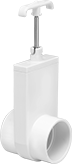
Plastic Socket-Connect Gradual On/Off Valves
Female ×
Socket-Connect Female
- Valve Type: Gate
- For Use With: Water
For a lightweight and economical alternative to metal valves, these are made of plastic. Insert unthreaded pipe into the socket ends and bond with PVC primer and cement to create a permanent, leak-tight connection. Valves gradually open and close to prevent system damage from suddenly starting and stopping flow. Pull the handle to open the valve. All valves have a rising stem that lifts as the valve opens and lowers as the valve closes to provide a visual indication of whether flow is on or off.
304 stainless steel gates are more durable than glass-filled polypropylene gates.
![]() For technical drawings and 3-D models, click on a part number.
For technical drawings and 3-D models, click on a part number.
O'all | |||||||||
|---|---|---|---|---|---|---|---|---|---|
| Pipe Size | Max. Pressure | Temp. Range, °F | End-to-End Lg. | Ht. | Lg. | Stem Type | Color | Each | |
Socket Connect Female × Socket Connect Female | |||||||||
PVC Plastic Body—304 Stainless Steel Gate | |||||||||
| 6 × 6 | 10 psi @ 120° F | 35° to 120° | 11 1/8" | 31 1/8" | 6 5/8" | Rising | White | 0000000 | 0000000 |
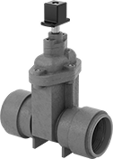
Gradual On/Off Valves with Push-to-Connect Fittings
- Valve Type: Gate
- For Use With: Water
- Seal Material: Buna-N Rubber
- Specifications Met: AWWA C515
For strong, permanent connections that are quick to install, push PVC pipe into these valves and a rubber ring grips it. Also known as gate valves, they open and close gradually to prevent damage to your system from sudden changes in flow. They meet AWWA (American Water Works Association) C515 for use in large-scale industrial cleaning and cooling water lines. Made of ductile iron, these valves are stronger than cast iron valves, so they resist cracking from pressure changes. The body is coated with epoxy to protect against corrosion. These valves have a rubber-coated gate, also known as a resilient wedge, that compresses against the valve for a long-lasting, leakproof seal. They'll seal tightly even when installed vertically, there's low back pressure, or the liquid contains solids and debris.
These valves fit well in tight spaces since the stem doesn’t rise when they open and they don’t have a handwheel. They’re wrench operated, which prevents them from opening accidentally when bumped or snagged. Use a valve wrench to open and close the valve with minimal effort. Their flanged stem housing, also known as a bolted bonnet, bolts in place so you can take them apart for repairs. However, the flanged stem housing makes these valves heavier and larger than valves with threaded or welded stem housings.
Flow coefficient (Cv) is the amount of water (in gallons per minute) at 60° F that will flow through a fully open valve with a difference of 1 psi between the inlet and the outlet.
![]() For technical drawings and 3-D models, click on a part number.
For technical drawings and 3-D models, click on a part number.
O'all | |||||||||||||
|---|---|---|---|---|---|---|---|---|---|---|---|---|---|
| Pipe Size | Flow Coefficient (Cv) | Max. Pressure | Temp. Range, °F | End-to-End Lg. | Ht. | Lg. | Stem Type | Stem Housing Connection Style | Valve Operation | Drive Style | Drive Size | Each | |
Epoxy-Coated Ductile Iron Body and Rubber-Coated Ductile Iron Gate | |||||||||||||
Push to Connect × Push to Connect | |||||||||||||
| 6 | 427 | 250 psi @ 72° F | -20° to 100° | 16 7/8" | 25" | 16 7/8" | Nonrising | Flanged | Wrench | External Square | 2" | 0000000 | 0000000 |
Flexible Joint Gradual On/Off Valves
- Valve Type: Gate
- For Use With: See table
- Seal Material: EPDM Rubber
- Specifications Met: See table
Flexible joints keep these valves tightly sealed during pressure changes or vibrations from heavy machinery. Also known as gate valves, they gradually open and close to prevent system damage from sudden flow changes. They have a rubber-coated gate that compresses against the valve for a long-lasting, leakproof seal. They’ll seal tightly even when installed vertically, when there’s low back pressure, or when the liquid contains solids and debris. Made of ductile iron, these valves are stronger than cast iron valves and resist cracking from pressure changes. The body is coated with epoxy to protect against corrosion. They meet at least one American Water Works Association (AWWA) standard for reliable and safe performance in water supply systems.
These valves fit well in tight spaces since the stem doesn’t rise when they open. Their flanged stem housing bolts in place for easy disassembly for maintenance and repairs. Use a valve wrench to open and close these valves. Because they require a wrench, they can’t be opened accidentally when bumped or snagged.
FM-approved valves are used in fire suppression and protection systems. They help isolate parts of water supply systems in buildings and plants.
Valves that meet NSF/ANSI 61 are safe to use with drinking water systems.
Flow coefficient (Cv) is the amount of water (in gallons per minute) at 60° F that will flow through a fully open valve with a difference of 1 psi between the inlet and the outlet.
![]() For technical drawings and 3-D models, click on a part number.
For technical drawings and 3-D models, click on a part number.
O'all | ||||||||||||||||
|---|---|---|---|---|---|---|---|---|---|---|---|---|---|---|---|---|
| Pipe Size | Flange OD | Bolt Circle Dia. | No. of Bolt Holes | Bolt Hole Dia. | Bolts Included | Retaining Ring Included | Flow Coefficient (Cv) | Max. Pressure | Temp. Range, °F | End-to-End Lg. | Ht. | Lg. | For Use With | Specifications Met | Each | |
Wrench Operated and Nonrising Stem—Red Epoxy-Coated Ductile Iron Body and Rubber-Coated Ductile Iron Gate | ||||||||||||||||
Flanged Stem Housing | ||||||||||||||||
| 6 | 11 1/16" | 9 1/2" | 4 | 7/8" | No | Yes | 423 | 300 psi @ 100° F | 35° to 170° | 10 1/2" | 24 1/2" | 10 1/2" | Water | AWWA C515, FM Approved, UL Listed | 0000000 | 0000000 |
| 6 | 11 1/16" | 9 1/2" | 4 | 7/8" | No | No | 2,250 | 300 psi @ 100° F | 33° to 180° | 11 1/2" | 22 3/4" | 11 1/2" | Water, Drinking Water | AWWA C151, AWWA C509, AWWA C515, NSF/ANSI 61 | 0000000 | 00000000 |
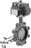
Flanged Air-Driven On/Off Valves

- Valve Type: Butterfly
- For Use With: Water, Air, Argon, Helium, Neon, Steam, Xenon, Krypton, Drinking Water
- Seal Material : EPDM Rubber
- Specifications Met: API 609, NSF/ANSI 61
To automatically start and stop flow faster than motor-driven valves, these operate on compressed air. You must control the air to the actuator using either the included electric pilot valve or a manual on/off valve (not included). Valves don’t require a minimum pressure drop between the inlet and outlet for operation.
The actuator is directly mounted to the valve body to minimize movement and reduce wear. A visual flow indicator on the top of the actuator shows whether the valve is open or closed. The manual override allows you to operate the valve during power outages. Valves meet NSF/ANSI 61 for use with drinking water.
All valves are lug style; their hole pattern matches ANSI flanges of the same pipe size. They can be sandwiched between two flanges, or bolt them directly to a single flange for servicing one end of the pipeline without depressurizing the other side.
Single-acting actuators only require air pressure to open the valve; they automatically spring closed when the air turns off. These valves are normally closed unless actuated. Double-acting actuators require air pressure to open and close the valve. Once actuated, these valves remain actuated until air pressure is applied, so they do not have a valve starting position.
Flow coefficient (Cv) is the amount of water (in gallons per minute) at 60° F that will flow through a fully open valve with a difference of 1 psi between the inlet and the outlet.
![]() For technical drawings and 3-D models, click on a part number.
For technical drawings and 3-D models, click on a part number.
Bolts | Air | ||||||||||||||
|---|---|---|---|---|---|---|---|---|---|---|---|---|---|---|---|
| Pipe Size | Flange OD | No. of Holes | Hole Size | Included | Circle Dia. | Flow Coefficient (Cv) | Max. Pressure | Pressure Drop | Temp. Range, °F | Valve Lg. | O'all Ht. | Connection | Pressure Range, psi | Each | |
Ductile Iron Body with Screw Terminals | |||||||||||||||
Single Acting: Air-to-Open, Spring Return (Normally Closed)—120V AC | |||||||||||||||
| 6 | 11" | 8 | 3/4" | No | 9 1/2" | 1,620 | 250 psi @ 100° F | Zero Pressure Drop | -30° to 250° | 2 3/16" | 22 1/2" | 1/4 NPT Female | 40 to 115 | 0000000 | 000000000 |
Double Acting: Air-to-Open, Air-to-Close—120V AC | |||||||||||||||
| 6 | 11" | 8 | 3/4" | No | 9 1/2" | 1,620 | 250 psi @ 100° F | Zero Pressure Drop | -30° to 250° | 2 3/16" | 19 15/16" | 1/4 NPT Female | 40 to 115 | 0000000 | 000000 |
Air-Driven On/Off Valves for Fuel
- Valve Type: Butterfly
- For Use With: Oil, Diesel Fuel, Ethylene Glycol, Kerosene, Butane, Fuel Oil, Gasoline, Natural Gas, Propane
- Seal Material : Viton® Fluoroelastomer Rubber
- Specifications Met: API 609, MSS-SP-67
Use these valves to safely transfer fuel and oil. They operate on compressed air to automatically start and stop flow faster than motor-driven valves. You must control the air to the actuator using either the included electric pilot valve or a manual on/off valve (not included). These valves don’t require a minimum pressure drop between the inlet and outlet for operation.
The actuator is directly mounted to the valve body to minimize movement and reduce wear. A visual flow indicator on the top of the actuator shows whether the valve is open or closed. The manual override allows you to operate the valve during power outages.
All valves are lug style; their hole pattern matches ANSI flanges of the same pipe size. They can be sandwiched between two flanges, or bolt them directly to a single flange for servicing one end of the pipeline without depressurizing the other side.
Single-acting actuators only require air pressure to open the valve; they automatically spring closed when the air turns off. These valves are normally closed unless actuated. Double-acting actuators require air pressure to open and close the valve. Once actuated, these valves remain actuated until air pressure is applied, so they do not have a valve starting position.
Flow coefficient (Cv) is the amount of water (in gallons per minute) at 60° F that will flow through a fully open valve with a difference of 1 psi between the inlet and the outlet.
![]() For technical drawings and 3-D models, click on a part number.
For technical drawings and 3-D models, click on a part number.
Bolts | Air | ||||||||||||||
|---|---|---|---|---|---|---|---|---|---|---|---|---|---|---|---|
| Pipe Size | Flange OD | No. of Holes | Hole Size | Included | Circle Dia. | Flow Coefficient (Cv) | Max. Pressure | Pressure Drop | Temp. Range, °F | Valve Lg. | O'all Ht. | Connection | Pressure Range, psi | Each | |
Ductile Iron Body with Screw Terminals | |||||||||||||||
Single Acting: Air-to-Open, Spring Return (Normally Closed)—120V AC | |||||||||||||||
| 6 | 11" | 8 | 3/4" | No | 9 1/2" | 1,620 | 250 psi @ 100° F | Zero Pressure Drop | 10° to 350° | 2 3/16" | 23 5/16" | 1/4 NPT Female | 40 to 115 | 0000000 | 000000000 |
Double Acting: Air-to-Open, Air-to-Close—120V AC | |||||||||||||||
| 6 | 11" | 8 | 3/4" | No | 9 1/2" | 1,620 | 250 psi @ 100° F | Zero Pressure Drop | 10° to 350° | 2 3/16" | 20 9/16" | 1/4 NPT Female | 40 to 115 | 0000000 | 00000000 |
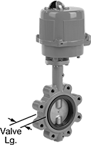
Flanged Motor-Driven On/Off Valves
- Valve Type: Butterfly
- For Use With: Water, Oil, Air, Natural Gas, Drinking Water, Propane, Butane, Argon, Helium, Neon, Steam, Xenon, Krypton
- Seal Material: EPDM Rubber
- Specifications Met: API 609, NSF/ANSI 61
Automatically start and stop flow in flanged pipelines with these valves that operate on electricity. All are fail in place; upon loss of power, the valve will remain in its current position.
The actuator is directly mounted to the valve body to minimize movement and reduce wear. A visual flow indicator on the top of the actuator shows whether the valve is open or closed. Two single pole, double throw (SPDT) auxiliary switches allow you to connect these valves to temperature-monitoring equipment, programmable logic controllers, or conveyor sirens. The internal heater automatically turns on when the valve is actuated to prevent motor damage caused by condensation buildup. Valves meet NSF/ANSI Standard 61 for use with drinking water.
All valves are lug style; their hole pattern matches ANSI flanges of the same pipe size. They can be sandwiched between two flanges, or bolt them directly to a single flange for servicing one end of the pipeline without depressurizing the other side.
Valves with a manual override can be operated during power outages.
Flow coefficient (Cv) is the amount of water (in gallons per minute) at 60° F that will flow through a fully open valve with a difference of 1 psi between the inlet and the outlet.
![]() For technical drawings and 3-D models, click on a part number.
For technical drawings and 3-D models, click on a part number.
Bolts | ||||||||||||||||
|---|---|---|---|---|---|---|---|---|---|---|---|---|---|---|---|---|
| Port Type | Pipe Size | Flange OD | No. of Holes | Hole Size | Included | Circle Dia. | Flow Coefficient (Cv) | Max. Pressure | Pressure Drop | Manual Override | Actuation Time, sec. | Temp. Range, °F | Valve Lg. | O'all Ht. | Each | |
Ductile Iron Body with Screw Terminals | ||||||||||||||||
Fail in Place—24V AC/DC | ||||||||||||||||
| Full | 6 | 11" | 8 | 3/4" | No | 9 1/2" | 1,620 | 250 psi @ 100° F | Zero Pressure Drop | Yes | 27 | -30° to 250° | 2 3/16" | 24 13/16" | 0000000 | 000000000 |
Fail in Place—120V AC | ||||||||||||||||
| Full | 6 | 11" | 8 | 3/4" | No | 9 1/2" | 1,620 | 250 psi @ 100° F | Zero Pressure Drop | Yes | 27 | -30° to 250° | 2 3/16" | 24 13/16" | 0000000 | 00000000 |
Motor-Driven On/Off Valves for Fuel
- Valve Type: Butterfly
- For Use With: Oil, Natural Gas, Propane, Butane, Diesel Fuel, Ethylene Glycol, Fuel Oil, Gasoline, Kerosene
- Seal Material: Viton® Fluoroelastomer Rubber
- Specifications Met: API 609, MSS-SP-67
Use these valves to safely transfer fuel and oil. They operate on electricity to automatically start and stop flow. All are fail in place; upon loss of power, the valve will remain in its current position.
The actuator is directly mounted to the valve body to minimize movement and reduce wear. A visual flow indicator on the top of the actuator shows whether the valve is open or closed. Two single pole, double throw (SPDT) auxiliary switches allow you to connect these valves to temperature-monitoring equipment, programmable logic controllers, or conveyor sirens. The internal heater automatically turns on when the valve is actuated to prevent motor damage caused by condensation buildup. The manual override allows you to operate the valve during power outages.
All valves are lug style; their hole pattern matches ANSI flanges of the same pipe size. They can be sandwiched between two flanges, or bolt them directly to a single flange for servicing one end of the pipeline without depressurizing the other side.
Flow coefficient (Cv) is the amount of water (in gallons per minute) at 60° F that will flow through a fully open valve with a difference of 1 psi between the inlet and the outlet.
![]() For technical drawings and 3-D models, click on a part number.
For technical drawings and 3-D models, click on a part number.
Bolts | ||||||||||||||
|---|---|---|---|---|---|---|---|---|---|---|---|---|---|---|
| Pipe Size | Flange OD | No. of Holes | Hole Size | Included | Circle Dia. | Flow Coefficient (Cv) | Max. Pressure | Pressure Drop | Actuation Time, sec. | Temp. Range, °F | Valve Lg. | O'all Ht. | Each | |
Ductile Iron Body with Screw Terminals | ||||||||||||||
Fail in Place—24V AC/24V DC | ||||||||||||||
| 6 | 11" | 8 | 3/4" | No | 9 1/2" | 1,620 | 250 psi @ 100° F | Zero Pressure Drop | 27 | 10° to 350° | 2 3/16" | 27 7/16" | 0000000 | 000000000 |
Fail in Place—120V AC | ||||||||||||||
| 6 | 11" | 8 | 3/4" | No | 9 1/2" | 1,620 | 250 psi @ 100° F | Zero Pressure Drop | 27 | 10° to 350° | 2 3/16" | 27 7/16" | 0000000 | 00000000 |