


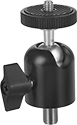
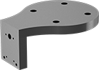
Ball-Grip Head Adapters for Adjustable-Height Positioning Stands
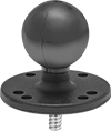
Mount components of Ball-Grip Positioning Arms to the top of a positioning stand or tripod.
Ball | Base | |||||||||||
|---|---|---|---|---|---|---|---|---|---|---|---|---|
| Max. Load Capacity, lbs. | Dia. | Material | Dia. | Material | Mount Type | Thread Size | No. of Mounting Holes | Mounting Hole Dia. | Mounting Fasteners Included | Includes | Each | |
| 10 | 1 1/2" | Rubber | 2 1/2" | Powder-Coated Aluminum | Threaded Stud, Screw On | 1/4"-20 | 7 | 7/32" | No | Removable Threaded Stud | 0000000 | 000000 |
Adjustable-Height Positioning Stands
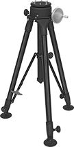
11-lb. capacity stands have an open head for use with optical and laser plumb instruments. The pointed feet provide stability on grass, gravel, and dirt.
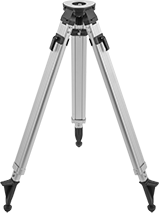
150-lb. capacity stands can be staked through the holes in the footplates.
| Max. Load Capacity, lbs. | Ht. | Head Dia. | Material | Mount Type | Thread Size | No. of Mounting Holes | Mounting Fasteners Included | Features | Each | |
| 11 | 42"-65" | 5" | Aluminum | Threaded Stud | 5/8"-11 | __ | No | Open Head, Pointed Feet with Rubber Pads | 0000000 | 0000000 |
| 150 | 33 1/2"-70" | 6" | Powder-Coated Aluminum | Threaded Hole | 1/4"-20, 5/16"-18 | 4,12 | Yes | 4" Dia. Self-Leveling Footplates with 5/8" Hole | 000000 | 00000000 |
Any-Angle Adjustable-Height Positioning Stands
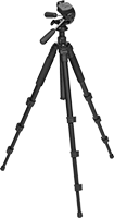
The head rotates 360° and tilts up and down.
Head | |||||||||||
|---|---|---|---|---|---|---|---|---|---|---|---|
| Load Capacity, lbs. | Ht. | Tilt Range of Motion | Lg. | Wd. | Material | Mount Type | Thread Size | Features | Includes | Each | |
| 9 | 11"-58" | 165° | 2 1/2" | 2 1/4" | Anodized Aluminum | Threaded Stud | 1/4"-20 | Quick-Release Attachment Plate | Storage Case | 000000 | 0000000 |
Flexible-Leg Positioning Stands
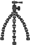
Bend and wrap the legs around almost anything while keeping a level mounting surface. Rubber rings around each section prevent slipping. These stands can also be used like a traditional tripod.
| Max. Load Capacity, lbs. | Ht. | Head Dia. | Leg Dia. | Material | Color | Mount Type | Thread Size | Each | |
| 1 | 4"-10 1/2" | 1 3/4" | 1" | Plastic | Black | Threaded Stud | 1/4"-20 | 0000000 | 000000 |
Heavy Duty Ball-Grip Positioning Arms
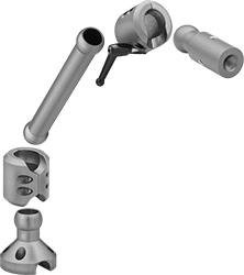
With strength for higher load capacities than other ball-grip positioning arms, these arms have a heavy duty construction. Ball-and-socket connections allow 360° positioning. The base, connectors, and links are hollow for routing wires, cables, and small hoses. Select a base, connectors, link, and plate or mount to build a complete arm.
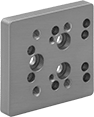
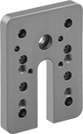
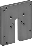
Mounting plates require a base and a straight or tee connector to attach to a link. Machine vision camera mounting plates come with mounting hole patterns for specific brand cameras.
Mount. | ||||||||
|---|---|---|---|---|---|---|---|---|
| Lg. | Wd. | Max. Load Capacity, lbs. | Material | Color | Fasteners Included | Hole Pattern Compatibility | Each | |
| 2 3/4" | 2 1/2" | 35 | Anodized Aluminum | Blue | Yes | Cognex In-Sight 2000 Cognex In-Sight 8000 | 0000000 | 000000 |
| 3" | 2 1/2" | 35 | Anodized Aluminum | Blue | Yes | Cognex Dataman 300 Cognex Dataman 302 Cognex Dataman 360 Cognex Dataman 470 Cognex Dataman 474 Cognex Dataman 70 Cognex In-Sight 7000 Cognex In-Sight 7800 | 0000000 | 00000 |
| 4" | 3 1/2" | 35 | Anodized Aluminum | Blue | Yes | Smart Vision ODS75 Smart Vision ODSW75 Smart Vision S75 Smart Vision SC75 Smart Vision SW75 | 0000000 | 00000 |
| 4 5/16" | 2 1/2" | 35 | Anodized Aluminum | Blue | Yes | BOA Cognex Checker 100 Cognex In-Sight 5000 DALSA DVT Legend 500 Dataman 100/200 Keyence IV-500/150/2000 | 0000000 | 00000 |
Ball-Grip Positioning Arms
Ball-and-socket connections allow 360° positioning. Choose a complete arm or select a base, connectors, and accessories to build your own.
To ensure compatibility, select components that have the same ball diameter. Use reducing connectors (sold separately) to pair components with a 1 1/2" ball diameter to those with a 1" ball diameter.
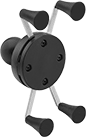
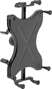
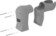
Hand-held device grips adjust for a secure hold.
Styles E and F have spring-loaded fingers that you can adjust to fit devices of different sizes. Rubber caps on the fingers create a tight grip on your smartphone or tablet.
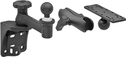
Bend-and-Stay Positioning Arms
Stronger and with greater load capacities than gooseneck-style positioning arms, these arms keep their shape even when moving or when exposed to vibration. They’re often used in robotics and conveyor applications when frequent repositioning isn’t required.
All accessories include the necessary hardware for attaching them to arms.
Ball-and-socket adapters and ball-and-socket connectors allow 360° rotation and up to 90° tilt. A locking knob keeps them in place.
Attaching End | Arm Attaching End | |||||||||||||
|---|---|---|---|---|---|---|---|---|---|---|---|---|---|---|
| Lg. | Rotation Range of Motion | Tilt Range of Motion | Mount Type | Mounting Thread Size | Mounting Thread Type | Max. Load Cap., lbs. | Body Material | Color | Mount Type | Mounting Thread Size | Mounting Thread Type | Features | Each | |
| 2 1/2" | 360° | 90° | Threaded Stud | 1/4"-20 | UNC | 6 | Anodized Aluminum | Black | Threaded Stud | 3/8"-24 | UNF | Locking Knob, Rubber-Padded Camera Seat | 00000000 | 000000 |
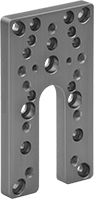
Mounts for Robot Machine Vision Cameras
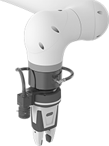
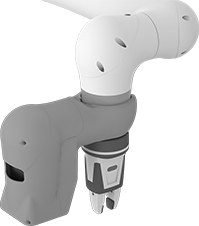
Use these mounts to attach a machine vision camera to the end of your robot arm. They have a standard ISO 50 mounting pattern and can be used with or without a tool. Use adapters (not included) to pair with tools that have different mounting patterns.
Plastic mounts fully enclose your camera and its cord to prevent it from getting damaged or knocked out of position. Once installed, the mounts’ front cover is removable, providing easy access for adjustments and maintenance.
For Machine Vision Camera | For Robot Arm | Overall | Machine Vision Camera Mount. Location | End of Robot Arm Mount. Location | |||||||||
|---|---|---|---|---|---|---|---|---|---|---|---|---|---|
| Manufacturer (Series) | Manufacturer Model No. | Manufacturer (Series) | Manufacturer Model No. | Lg., mm | Wd., mm | Ht., mm | Mount. Fasteners Included | Bolt Hole Dia. (No. of Holes) | Bolt Hole Thread Size (No. of Holes) | Mount. Fasteners Included | Bolt Circle Dia. (Mount. Hole Pattern Compatibility) | Each | |
Aluminum | |||||||||||||
| FANUC (IR Vision) | A05B-1426-K001 | FANUC (CRX) | 5iA 10iA 10iA/L 20iA/L 25iA | 98 | 95 | 49 | Yes | 2.4 mm (4), 3.4 mm (3) | __ | Yes | 50 mm (ISO 50) | 0000000 | 0000000 |
Nylon Plastic | |||||||||||||
| FANUC (IR Vision) | A05B-1426-B102 A05B-1426-B103 A05B-1426-B104 A05B-1426-B112 A05B-1426-B114 | FANUC (CRX) | 5iA 10iA 10iA/L 20iA/L 25iA | 281 | 114 | 208 | Yes | __ | M6 × 1 mm (4) | No | 50 mm (ISO 50) | 0000000 | 00000000 |
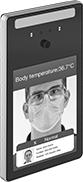
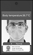
Non-Contact Temperature Screeners
Quickly take people’s temperatures as they enter your facility to screen out anyone with a high reading. These screeners have a thermal camera that uses infrared light to measure forehead temperature in two seconds at a distance of one to two feet. They’re accurate within 0.9° F and 0.5° C, and work even if people are wearing masks, hats, and glasses. If their temperature is normal, there’s an audible notification. Connect them to your network using Wi-Fi or their Ethernet port in order to create a library of photos, retain data for reporting, and customize the screeners to display directions and your company name and logo. For basic temperature scanning only, there’s no need to connect them to your network—simply plug their power cord into a wall outlet. If you want to keep people from entering until they pass the temperature check, wire these screeners to doors and gates. CE marked, they meet European safety, health, and environmental protection requirements.
Mount these screeners to a wall, or add a floor stand.
Warning: These screeners are not intended for medical use.
| Temperature Range | Resolution | Accuracy | Max. Working Distance, ft. | Response Time, sec. | Ht. | Wd. | Dp. | Housing Material | Specifications Met | Cord Lg., ft. | Mounting Fasteners Included | Each | |
| 89° to 106° F/31° to 41° C | 0.1° F/0.1° C | ±0.9° F/±0.5° C | 2 | 2 | 10 1/8" | 5 7/16" | 1 13/16" | 6061 Aluminum | CE Marked | 5 | Yes | 0000000 | 000000000 |
| Component | Ht. | Lg. | Wd. | Each | |
| Floor Stand | 45" | 11 5/8" | 14" | 0000000 | 0000000 |