


Filter by
Mounting Pattern Compatibility

Finish
Export Control Classification Number (ECCN)
Adjustment Movement
DFARS Specialty Metals
Robot Cell Component

Connection Material
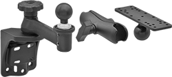
Heavy Duty Ball-Grip Positioning Arms
 |  |  |  |  |
Arm Built with Base, Two Straight Connectors, Straight Link, Locking Handle, and Sensor Mount | Machine Vision Camera Mounting Plates, Style A | Machine Vision Camera Mounting Plates, Style B | Machine Vision Camera Mounting Plates, Style C | Machine Vision Camera Mounting Plates, Style D |
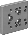
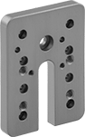
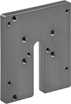
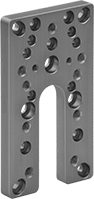
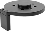
Machine Vision Camera Mounting Plates
| | | |
Style A | Style B | Style C | Style D |
Mounting | ||||||||||||
|---|---|---|---|---|---|---|---|---|---|---|---|---|
Style | Lg. | Wd. | Max. Load Cap., lb. | Material | Color | Fasteners Included | Pattern Compatibility | No. of Holes | Each | |||
Rotate, Tilt, Side to Side, In/Out | ||||||||||||
| A | 2 3/4" | 2 1/2" | 30 | Anodized Aluminum | Blue | Yes | Cognex In-Sight 2000 Cognex In-Sight 8000 | 17 | 1530N32 | 000000 | ||
| B | 3" | 2 1/2" | 30 | Anodized Aluminum | Blue | Yes | Cognex Dataman 300 Cognex Dataman 302 Cognex Dataman 360 Cognex Dataman 470 Cognex Dataman 474 Cognex Dataman 70 Cognex In-Sight 7000 Cognex In-Sight 7800 | 17 | 1530N31 | 00000 | ||
| C | 4" | 3 1/2" | 30 | Anodized Aluminum | Blue | Yes | Smart Vision ODS75 Smart Vision ODSW75 Smart Vision S75 Smart Vision SC75 Smart Vision SW75 | 12 | 1530N33 | 00000 | ||
| D | 4 5/16" | 2 1/2" | 30 | Anodized Aluminum | Blue | Yes | DALSA BOA Cognex Checker 100 Cognex In-Sight 5000 DALSA DVT Legend 500 Cognex Dataman 100 Cognex Dataman 200 Keyence IV-500/150/2000 | 29 | 1530N23 | 00000 | ||
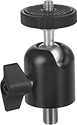
Ball-Grip Head Adapters for Adjustable-Height Positioning Stands
 |
Mount components of Ball-Grip Positioning Arms to the top of a positioning stand or tripod.
Ball | Base | ||||||||||||
|---|---|---|---|---|---|---|---|---|---|---|---|---|---|
Max. Load Cap., lb. | Dia. | Material | Dia. | Material | Mount Type | Thread Size | No. of Mounting Holes | Mounting Hole Dia. | Mounting Fasteners Included | Includes | Each | ||
| 10 | 1 1/2" | Rubber | 2 1/2" | Powder-Coated Aluminum | Threaded Stud, Screw On | 1/4"-20 | 7 | 7/32" | No | Removable Threaded Stud | 5031T55 | 000000 | |
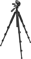
Adjustable-Height Tripods
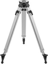 | 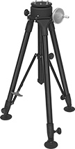 |
11 lb. Maximum Load Capacity | 150 lb. Maximum Load Capacity |
11 lb. Maximum Load Capacity—11-lb. maximum load capacity tripods have an open head for use with optical and laser plumb instruments. The pointed feet provide stability on grass, gravel, and dirt.
150 lb. Maximum Load Capacity—150-lb. maximum load capacity tripods can be staked through the holes in the footplates.
Max. Load Cap., lb. | Ht. | Head Dia. | Material | Color | Mount Type | Thread Size | No. of Mounting Holes | Mounting Fasteners Included | Features | Each | ||
|---|---|---|---|---|---|---|---|---|---|---|---|---|
| 11 | 42" to 65" | 5" | Aluminum | — | Threaded Stud | 5/8"-11 | — | No | Open Head, Pointed Feet with Rubber Pads | 8973A81 | 0000000 | |
| 150 | 33 1/2" to 70" | 6" | Powder-Coated Aluminum | Black | Threaded Hole | 1/4"-20, 5/16"-18 | 4, 12 | Yes | 4" Dia. Self-Leveling Footplates with 5/8" Hole | 1425A7 | 00000000 |
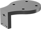
Machine Vision Camera Mounts for Robots
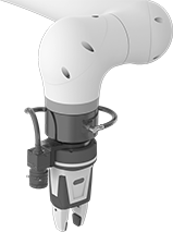 |
Mount on Robot Arm (Sold Separately) |
 |
For FANUC Cameras |
 |
Drill-Your-Own Mounting Patterns |
 |
Attach a machine vision camera to the end of your robot arm. These mounts are compatible with most robot arms, including FANUC CRX and Universal Robot (UR) models. You can also use the same mounting holes to attach a robot tool.
Drill-Your-Own Mounting Patterns—Drill holes to match your camera’s mounting hole pattern.
For Machine Vision Camera | For End of Robot Arm | |||||||||||
|---|---|---|---|---|---|---|---|---|---|---|---|---|
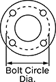
Mfr. Series | Mfr. Model No. | Bolt Circle Dia. (Mounting Pattern Compatibility) | Mount Type | Mounting Fasteners Included | Lg., mm | Wd., mm | Ht., mm | Material | Each | |||
For FANUC Machine Vision Cameras | ||||||||||||
| IR Vision | A05B-1426-K001 | 50 mm (ISO 50) | Bolt On | No | 98 | 95 | 49 | Black Anodized Aluminum | 7715N13 | 0000000 | ||
Drill-Your-Own Mounting Patterns | ||||||||||||
| — | — | 50 mm (ISO 50) | Bolt On | No | 102 | 93 | 42 | Black Anodized Aluminum | 7715N14 | 000000 | ||
Bend-and-Stay Positioning Arms
Ball-and-Socket Adapters
 |
Ball-and-socket adapters allow 360° rotation and up to 90° tilt. A locking knob keeps them in place.
Attaching End | Arm Attaching End | ||||||||||||||
|---|---|---|---|---|---|---|---|---|---|---|---|---|---|---|---|
Lg. | Range of Motion | Max. Tilt Range of Motion | Mounting Thread Size | Mounting Thread Type | Max. Load Cap., lb. | Body Material | Color | Mount Type | Mounting Thread Size | Mounting Thread Type | Features | Each | |||
Threaded Stud | |||||||||||||||
| 2 1/2" | 360° | 90° | 1/4"-20 | UNC | 6 | Anodized Aluminum | Black | Threaded Stud | 3/8"-24 | UNF | Locking Knob, Rubber-Padded Camera Seat | 3883N125 | 000000 | ||
Ball-Grip Positioning Arms
 | 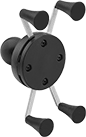 | 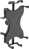 |
Arm Built with Rotating Complete Arm with Ball, Rigid Connector, and Universal Mounting Plate | For Tablets—Handheld Device Grips, Style E | For Tablets—Handheld Device Grips, Style F |
For Smartphones—Handheld Device Grips
|
Style E |
Style | For Diag. Screen Size | Ball Dia. | Max. Load Cap., lb. | Material | Ball Material | Color | Each | |||
|---|---|---|---|---|---|---|---|---|---|---|
Rotate, Tilt, Side to Side, In/Out | ||||||||||
| E | 4.5" to 6.2" | 1" | 1 | Plastic | Rubber | Black | 5031T138 | 000000 | ||
Any-Angle Adjustable-Height Tripods Tripods
 |
The head rotates 360° and tilts up and down.
Head | |||||||||||||
|---|---|---|---|---|---|---|---|---|---|---|---|---|---|
Max. Load Cap., lb. | Ht. | Tilt Range of Motion | Lg. | Wd. | Material | Color | Mount Type | Thread Size | Features | Includes | Each | ||
| 9 | 11" to 58" | 165° | 2 1/2" | 2 1/4" | Anodized Aluminum | Black | Threaded Stud | 1/4"-20 | Quick-Release Attachment Plate | Storage Case | 1425A5 | 0000000 | |
Flexible-Leg Tripods
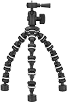 |
Bend and wrap the legs around almost anything while keeping a level mounting surface. Rubber rings around each section prevent slipping. These tripods can also be used like a traditional tripod.
Max. Load Cap., lb. | Ht. | Head Dia. | Leg Dia. | Material | Color | Mount Type | Thread Size | Each | ||
|---|---|---|---|---|---|---|---|---|---|---|
| 5 | 3 1/2" to 10" | 2" | 2" | Plastic | Black | Threaded Stud | 1/4"-20 | 1050A12 | 000000 |
