


Filter by
Draw Latch Type

Mounting Location
System of Measurement
Overall Length

Latching Distance Adjustability
Weight Capacity
Strike Plate Material
Latching Distance

Strike Plate Shape
Adjustability
Overall Width
Length
RoHS
DFARS Specialty Metals
Export Control Classification Number (ECCN)
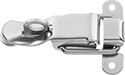
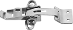
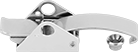
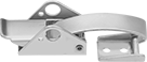
Adjustable-Grip Padlockable Draw Latches
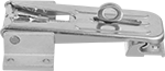 | ||
Style A | Style B | Style C |
Style D | Style E | Style F |
Style G | Style H |
Overall | Mounting | ||||||||||||||
|---|---|---|---|---|---|---|---|---|---|---|---|---|---|---|---|
Style | Material | Strike Plate Material | Appearance | Latching Distance | Lg. | Wd. | Projection | Wt. Cap., lb. | For Max. Padlock Shackle Dia. | Fasteners Included | Screw Size | Each | |||
| A | Zinc-Plated Steel | — | Dull | 2 1/2" to 3" | 4 1/4" | 1 5/16" | 1 1/8" | Not Rated | 1/4" | No | No. 10 | 1864A26 | 000000 | ||
| A | 300 Series Stainless Steel | — | Dull | 2 1/2" to 3" | 4 1/4" | 1 5/16" | 1 1/8" | Not Rated | 1/4" | No | No. 10 | 1864A28 | 00000 | ||
| B | Zinc-Yellow-Chromate-Plated Steel | — | Dull | 1" to 1 9/16" | 2 3/4" | 1 1/8" | 1 1/16" | Not Rated | 1/4" | No | No. 8 | 1864A19 | 00000 | ||
| B | 300 Series Stainless Steel | — | Dull | 1" to 1 9/16" | 2 3/4" | 1 1/8" | 1 1/16" | Not Rated | 1/4" | No | No. 8 | 1864A21 | 00000 | ||
| B | 304 Stainless Steel | — | Dull | 1 3/8" to 2 1/2" | 5 1/4" | 1 3/4" | 1 1/4" | 800 | 5/16" | No | No. 10 | 1807A62 | 00000 | ||
| C | Zinc-Plated Steel | Aluminum | Dull | 2 3/4" to 3 1/4" | 5 3/16" | 3" | 1 5/8" | Not Rated | 3/8" | No | No. 10 | 1807A58 | 00000 | ||
| D | Zinc-Plated Steel | — | Dull | 1 5/16" to 1 7/8" | 10 3/16" | 1 3/8" | 1 1/2" | 4,400 | 5/16" | No | 5/16" | 6304A51 | 00000 | ||
| D | Zinc-Plated Steel | — | Dull | 1 5/16" to 3 5/8" | 11 15/16" | 1 3/8" | 1 1/2" | 4,400 | 5/16" | No | 5/16" | 6304A55 | 00000 | ||
| D | 304 Stainless Steel | — | Polished | 1 5/16" to 1 7/8" | 10 3/16" | 1 3/8" | 1 1/2" | 5,500 | 5/16" | No | 5/16" | 6304A53 | 000000 | ||
| D | 304 Stainless Steel | — | Polished | 1 5/16" to 3 5/8" | 11 15/16" | 1 3/8" | 1 1/2" | 5,500 | 5/16" | No | 5/16" | 6304A57 | 000000 | ||
| E | Zinc-Plated Steel | — | Dull | 1 3/16" to 1 7/16" | 4" | 1 3/16" | 11/16" | 220 | 3/16" | No | No. 8 | 13435A31 | 00000 | ||
| E | Zinc-Plated Steel | — | Dull | 2" to 2 1/2" | 5 3/8" | 1 5/16" | 11/16" | 660 | 3/16" | No | No. 10 | 13435A32 | 00000 | ||
| E | Zinc-Plated Steel | — | Dull | 2 5/16" to 2 3/4" | 7 1/8" | 1 5/8" | 1" | 1,100 | 3/8" | No | No. 10 | 13435A33 | 00000 | ||
| E | 316 Stainless Steel | — | Polished | 1 3/16" to 1 7/16" | 4" | 1 3/16" | 11/16" | 220 | 3/16" | No | No. 8 | 13435A41 | 00000 | ||
| E | 316 Stainless Steel | — | Polished | 2" to 2 1/2" | 5 3/8" | 1 5/16" | 11/16" | 660 | 3/16" | No | No. 10 | 13435A42 | 00000 | ||
| E | 316 Stainless Steel | — | Polished | 2 5/16" to 2 3/4" | 7 1/8" | 1 5/8" | 1" | 1,100 | 3/8" | No | No. 10 | 13435A43 | 00000 | ||
| F | Galvanized Steel | — | Dull | 1 5/8" to 2 1/8" | 6 7/8" | 1 13/16" | 7/8" | Not Rated | 1/4" | No | No. 10, No. 6 | 13435A61 | 00000 | ||
| G | Zinc-Plated Steel | — | Dull | 2 1/8" to 2 7/8" | 6 1/4" | 2" | 15/16" | 1,100 | 3/8" | No | No. 10 | 13435A36 | 00000 | ||
| G | Zinc-Plated Steel | — | Dull | 2 5/16" to 3" | 7 11/16" | 2" | 15/16" | 1,300 | 3/8" | No | No. 10 | 13435A35 | 00000 | ||
| H | Zinc-Plated Steel | — | Dull | 2 1/8" to 2 11/16" | 6 11/16" | 1 5/8" | 1" | 1,100 | 3/16" | No | No. 10 | 13435A51 | 00000 | ||
| H | 316 Stainless Steel | — | Polished | 2 1/8" to 2 11/16" | 6 11/16" | 1 5/8" | 1" | 1,100 | 3/16" | No | No. 10 | 13435A52 | 00000 | ||
Padlockable Draw Latches
 |  | |
Style A | Style B | Style C |
 |  |  |
Style D | Style E | Style F |
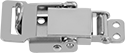 | 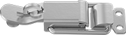 |  |
Style G | Style H | Style J |
 | ||
Style K | Style L |
Latches | Replacement Latch Strike Plates | ||||||||||||||||
|---|---|---|---|---|---|---|---|---|---|---|---|---|---|---|---|---|---|
Overall | Mounting | ||||||||||||||||
Style | Material | Appearance | Latching Distance | Lg. | Wd. | Projection | Wt. Cap., lb. | For Max. Padlock Shackle Dia. | Fasteners Included | Screw Size | Pkg. Qty. | Pkg. | Each | ||||
Screw On | |||||||||||||||||
| A | Zinc-Plated Steel | Dull | 1 5/16" | 3 7/8" | 1 5/16" | 15/16" | Not Rated | 5/16" | No | No. 10 | 3 | 1767A41 | 000000 | ——— | 0 | ||
| A | 304 Stainless Steel | Polished | 13/16" | 3 1/8" | 1 1/4" | 1/2" | Not Rated | 3/16" | No | No. 4 | 1 | 1889A46 | 00000 | ——— | 0 | ||
| B | Zinc-Plated Steel | Dull | 1 1/16" | 2 9/16" | 1 5/8" | 13/16" | Not Rated | 1/4" | No | No. 6 | 5 | 1590A14 | 0000 | ——— | 0 | ||
| B | Zinc-Plated Steel | Polished | 2 9/16" | 2 1/2" | 7/8" | 3/4" | Not Rated | 1/4" | No | No. 6 | 1 | 1734A51 | 0000 | 1734A61 | 00000 | ||
| B | 300 Series Stainless Steel | Dull | 1 1/16" | 2 9/16" | 1 5/8" | 13/16" | Not Rated | 1/4" | No | No. 6 | 1 | 1590A45 | 0000 | ——— | 0 | ||
| B | 300 Series Stainless Steel | Dull | 2 9/16" | 2 1/2" | 7/8" | 3/4" | Not Rated | 1/4" | No | No. 6 | 1 | 1734A52 | 00000 | 1734A62 | 0000 | ||
| C | Nickel-Plated Steel | Dull | 13/16" | 3 3/4" | 2" | 5/8" | Not Rated | 3/16" | No | No. 4, No. 5 | 5 | 1766A61 | 00000 | ——— | 0 | ||
| D | 300 Series Stainless Steel | Polished | 1 9/16" | 4" | 1 7/8" | 7/8" | 380 | 3/8" | No | No. 12 | 1 | 1863A31 | 00000 | ——— | 0 | ||
| E | Zinc-Plated Steel | Dull | 1 11/16" | 3 3/8" | 15/16" | 15/16" | 285 | 5/16" | No | No. 8 | 1 | 1844A43 | 00000 | ——— | 0 | ||
| E | 17-7 PH Stainless Steel | Polished | 1 11/16" | 3 3/8" | 15/16" | 15/16" | 200 | 5/16" | No | No. 8 | 1 | 1844A23 | 00000 | ——— | 0 | ||
| F | Zinc-Plated Steel | Dull | 1 11/16" | 3 3/8" | 15/16" | 15/16" | 285 | 5/16" | No | No. 8 | 1 | 1844A53 | 00000 | ——— | 0 | ||
| F | 17-7 PH Stainless Steel | Polished | 1 11/16" | 3 3/8" | 15/16" | 15/16" | 200 | 5/16" | No | No. 8 | 1 | 1844A33 | 00000 | ——— | 0 | ||
| G | 300 Series Stainless Steel | Dull | 1 5/16" | 2 3/4" | 1 3/16" | 15/16" | 400 | 3/8" | No | No. 6 | 1 | 1794A54 | 00000 | ——— | 0 | ||
| H | Zinc-Plated Steel | Polished | 3 7/8" | 3 7/8" | 1 1/4" | 15/16" | Not Rated | 3/8" | No | No. 10 | 1 | 1734A53 | 0000 | 1734A63 | 0000 | ||
| H | 300 Series Stainless Steel | Dull | 3 7/8" | 3 7/8" | 1 1/4" | 15/16" | Not Rated | 3/8" | No | No. 10 | 1 | 1734A54 | 00000 | 1734A64 | 0000 | ||
| J | Zinc-Plated Steel | Polished | 4 1/2" | 3 5/8" | 1 7/8" | 7/8" | Not Rated | 1/4" | No | No. 10 | 1 | 1734A59 | 00000 | 1734A67 | 0000 | ||
Weld On | |||||||||||||||||
| K | Steel | Dull | 1 5/16" | 3 7/8" | 1 5/16" | 15/16" | Not Rated | 5/16" | — | — | 3 | 1767A42 | 0000 | ——— | 0 | ||
| L | Steel | Dull | 1 1/16" | 2 9/16" | 1 5/8" | 13/16" | Not Rated | 1/4" | — | — | 10 | 1767A15 | 00000 | ——— | 0 | ||
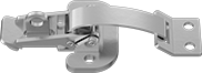
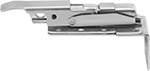
Corner-Mount Padlockable Draw Latches
 |
Add a padlock to secure these latches, which reach around corners to pull two surfaces together. The overall length listed includes the strike plate.
Overall | Mounting | Straight Strike Plate | ||||||||||||
|---|---|---|---|---|---|---|---|---|---|---|---|---|---|---|
Material | Appearance | Latching Distance | Lg. | Wd. | Projection | Wt. Cap., lb. | For Max. Padlock Shackle Dia. | Fasteners Included | Screw Size | Features | Each | |||
| Zinc-Plated Steel | Dull | 1 11/16" | 3 7/16" | 1 9/16" | 1" | 310 | 5/16" | No | M5 | Safety Catch | 4202N11 | 000000 | ||
Weather-Resistant Padlockable Draw Latches
 |
This latch has a rubber body that absorbs vibration and stretches to compensate for slight misalignment. The overall length listed includes the strike plate.
Overall | Mounting | ||||||||||||
|---|---|---|---|---|---|---|---|---|---|---|---|---|---|
Material | Strike Plate Material | Latching Distance | Lg. | Wd. | Projection | Wt. Cap. | For Max. Padlock Shackle Dia. | Fasteners Included | Screw Size | Each | |||
| Black Rubber | 300 Series Stainless Steel | 3 9/16" | 4 3/16" | 1 1/4" | 15/16" | Not Rated | 5/16" | No | No. 8 | 1070A91 | 000000 | ||
Turn-to-Open Padlockable Draw Latches
 | 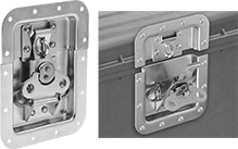 |
Surface Mount | Mortise Mount |
Lift and turn the handle 180° to open and close these latches. Capacity is the maximum amount of force the latch can withstand.
Mortise Mount—Mortise-mount latches are recessed to create a nearly flat surface that protects the latch from damage. They also have a spring-loaded handle that provides a tight hold and compensates for slight misalignment.
Overall | For Cutout | Mounting | ||||||||||||||
|---|---|---|---|---|---|---|---|---|---|---|---|---|---|---|---|---|
Material | Appearance | Latching Distance | Lg. | Wd. | Projection | Wt. Cap., lb. | For Max. Padlock Shackle Dia. | Ht. | Wd. | Dp. | Fasteners Included | Screw Size | Each | |||
Surface Mount | ||||||||||||||||
| Zinc-Plated Steel | Dull | 3/4" | 2 9/16" | 1 1/2" | 15/16" | 300 | 3/8" | — | — | — | No | No. 4 | 1406A54 | 00000 | ||
| 300 Series Stainless Steel | Dull | 3/4" | 2 9/16" | 1 1/2" | 15/16" | 300 | 3/8" | — | — | — | No | No. 4 | 1406A43 | 00000 | ||
Mortise Mount | ||||||||||||||||
| Zinc-Plated Steel | Dull | 1 1/16" | 6 1/4" | 5" | 1/16" | Not Rated | 3/8" | 5 1/8" | 3 13/16" | 9/16" | No | No. 10 | 10425A86 | 00000 | ||
Corner-Mount Tight-Hold Padlockable Draw Latches with Safety Catch
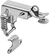 |
Mount this latch on a corner to draw perpendicular surfaces together. It has a safety catch to prevent accidental opening. Designed with compression springs to withstand vibration better than standard padlockable draw latches, it offers a more secure hold. The overall length listed includes the strike plate.
Overall | Mounting | Straight Strike Plate | ||||||||||||
|---|---|---|---|---|---|---|---|---|---|---|---|---|---|---|
Material | Appearance | Latching Distance | Lg. | Wd. | Projection | Wt. Cap. | For Max. Padlock Shackle Dia. | Fasteners Included | Screw Size | Features | Each | |||
| 304 Stainless Steel | Polished | 1 1/8" | 2 9/16" | 1 9/16" | 5/8" | Not Rated | 3/16" | No | M4 | Safety Catch | 6148A25 | 000000 | ||
Strikeless Adjustable-Grip Draw Latches
Vinyl-Coated Handle Zinc-Plated Steel | Vinyl-Coated Handle Black Powder-Coated Steel |
These latches hook into a lip or notch and have an adjustable latching distance to compensate for gasketing and misalignment. Capacity is the maximum amount of force the latch can withstand. The overall length listed is measured with the latch extended to maximum latching distance.
Vinyl-Coated Handle—For the best grip, choose a latch with a vinyl-coated handle.
Yellow Handle—The bright yellow vinyl handle makes the latch easy to see.
Overall | Mounting | ||||||||||||
|---|---|---|---|---|---|---|---|---|---|---|---|---|---|
Material | Appearance | Latching Distance | Lg. | Wd. | Projection | Wt. Cap., lb. | Handle Color | Fasteners Included | Screw Size | Each | |||
Vinyl-Coated Handle | |||||||||||||
| Zinc-Plated Steel | Dull | 3 1/2" to 4 1/2" | 12 1/2" | 1 3/4" | 1 13/16" | 500 | Yellow | No | 5/16" | 11605A25 | 0000000 | ||
| Black Powder-Coated Steel | Dull | 3 1/2" to 4 1/2" | 12 1/2" | 1 3/4" | 1 13/16" | 500 | Black | No | 5/16" | 11605A26 | 000000 | ||
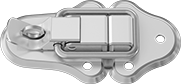
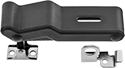
Multiple-Strike Padlockable Draw Latches
 |
Each latch comes with a variety of strike plates for different mounting options. Capacity is the maximum amount of force the latch can withstand. The overall length and width listed includes the longest and widest strike.
Overall | Mounting | ||||||||||||
|---|---|---|---|---|---|---|---|---|---|---|---|---|---|
Material | Appearance | Latching Distance | Lg. | Wd. | Projection | Wt. Cap., lb. | For Max. Padlock Shackle Dia. | Fasteners Included | Screw Size | Each | |||
Three Strike Plates | |||||||||||||
| Zinc-Plated Steel | Dull | 1 1/16" | 6" | 1 5/16" | 15/16" | 990 | 9/32" | No | No. 10 | 2165N1 | 000000 | ||
| Black Powder-Coated Steel | Dull | 1 1/16" | 6" | 1 5/16" | 15/16" | 990 | 9/32" | No | No. 10 | 2165N2 | 00000 | ||
| 304 Stainless Steel | Dull | 1 1/16" | 6" | 1 5/16" | 15/16" | 990 | 9/32" | No | No. 10 | 2165N3 | 00000 | ||
Ultra-Tight-Hold Padlockable Draw Latches
 | 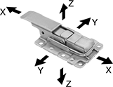 | ||
Door-Face Mount | Inside-Corner Mount | Outside-Corner Mount |
Cap., lb. | Overall | Mounting | |||||||||||||
|---|---|---|---|---|---|---|---|---|---|---|---|---|---|---|---|
Material | Appearance | Latching Distance | X-Axis | Y-Axis | Z-Axis | Lg. | Wd. | Projection | For Max. Padlock Shackle Dia. | Fasteners Included | Screw Size | Each | |||
Door-Face Mount | |||||||||||||||
| Zinc-Plated Steel | Dull | 3/4" | 880 | 880 | 1,950 | 3 15/16" | 1 13/16" | 11/16" | 3/16" | No | No. 6 | 6682A31 | 000000 | ||
| 304 Stainless Steel | Polished | 3/4" | 1,300 | 1,300 | 1,950 | 3 15/16" | 1 13/16" | 11/16" | 3/16" | No | No. 6 | 6682A32 | 00000 | ||
Inside-Corner Mount | |||||||||||||||
| Zinc-Plated Steel | Dull | 3/4" | 880 | 220 | 220 | 4 3/16" | 1 13/16" | 1 1/8" | 3/16" | No | No. 6 | 6682A35 | 00000 | ||
| 304 Stainless Steel | Polished | 3/4" | 1,300 | 220 | 220 | 4 3/16" | 1 13/16" | 1 1/8" | 3/16" | No | No. 6 | 6682A36 | 00000 | ||
Outside-Corner Mount | |||||||||||||||
| Zinc-Plated Steel | Dull | 3/4" | 880 | 330 | 220 | 4 3/16" | 1 13/16" | 1 13/16" | 3/16" | No | No. 6 | 6682A39 | 00000 | ||
| 304 Stainless Steel | Polished | 3/4" | 1,300 | 330 | 220 | 4 3/16" | 1 13/16" | 1 13/16" | 3/16" | No | No. 6 | 6682A41 | 00000 | ||
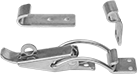
Strikeless Padlockable Draw Latches
Style A | Style B |
No need for a strike plate, these latches hook into a lip or notch. Capacity is the maximum amount of force the latch can withstand.
Overall | Mounting | ||||||||||||||
|---|---|---|---|---|---|---|---|---|---|---|---|---|---|---|---|
Style | Material | Appearance | Latching Distance | Lg. | Wd. | Projection | Wt. Cap., lb. | For Max. Padlock Shackle Dia. | Fasteners Included | Screw Size | Pkg. Qty. | Pkg. | |||
| A | Zinc-Plated Steel | Dull | 1 1/2" | 3 1/8" | 7/8" | 13/16" | Not Rated | 5/16" | No | No. 6 | 5 | 1767A43 | 00000 | ||
| B | Zinc-Plated Steel | Dull | 1 3/8" | 4 9/16" | 1 3/16" | 15/16" | 660 | 1/4" | No | No. 10 | 1 | 6082A19 | 0000 | ||
| B | 304 Stainless Steel | Polished | 1 3/8" | 4 9/16" | 1 3/16" | 15/16" | 425 | 1/4" | No | No. 10 | 1 | 6082A21 | 00000 | ||
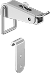
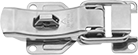
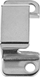
Tight-Hold Padlockable Draw Latches
 |  |  |
Style A | Style B | Replacement Latch Strike Plates |
Latches | Replacement Latch Strike Plates | |||||||||||||||
|---|---|---|---|---|---|---|---|---|---|---|---|---|---|---|---|---|
Overall | Mounting | |||||||||||||||
Style | Material | Appearance | Latching Distance | Lg. | Wd. | Projection | Wt. Cap. | For Max. Padlock Shackle Dia. | Fasteners Included | Screw Size | Each | Each | ||||
| A | Zinc-Plated Steel | Polished | 1 1/16" | 3" | 1 3/8" | 13/16" | Not Rated | 5/16" | No | No. 6 | 1734A11 | 00000 | 1734A71 | 00000 | ||
| A | Zinc-Plated Steel | Polished | 1 1/4" | 3 5/8" | 1 13/16" | 15/16" | Not Rated | 3/8" | No | No. 10, No. 12 | 1734A15 | 00000 | 1734A72 | 0000 | ||
| B | Zinc-Plated Steel | Polished | 4 1/16" | 3 3/16" | 1 7/8" | 7/8" | Not Rated | 3/8" | No | No. 10 | 1734A55 | 0000 | 1734A65 | 0000 | ||
| B | 300 Series Stainless Steel | Dull | 4 1/16" | 3 3/16" | 1 7/8" | 7/8" | Not Rated | 3/8" | No | No. 10 | 1734A56 | 00000 | 1734A66 | 0000 | ||
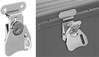
Gasket-Sealing Padlockable Draw Latches with Safety Catch
 |  |  |
Latch Shown Mounted | Replacement Draw Latch Keeper Plates |
For use on gasketed doors, these latches use downward compression to pull surfaces together. Capacity is the maximum amount of force the latch can withstand. The overall length listed includes the strike plate.
Latches | Replacement Draw Latch Keeper Plates | ||||||||||||||
|---|---|---|---|---|---|---|---|---|---|---|---|---|---|---|---|
Overall | Mounting | ||||||||||||||
Material | Appearance | Latching Distance | Lg. | Wd. | Projection | Wt. Cap., lb. | For Max. Padlock Shackle Dia. | Fasteners Included | Screw Size | Each | Each | ||||
Surface Mount | |||||||||||||||
| Zinc-Plated Steel | Dull | 1" | 4 3/16" | 1 13/16" | 3/4" | 415 | 1/4" | No | No. 10 | 4567A12 | 000000 | 4567A18 | 00000 | ||
| 304 Stainless Steel | Dull | 1" | 4 3/16" | 1 13/16" | 3/4" | 400 | 1/4" | No | No. 10 | 4567A13 | 00000 | 4567A19 | 0000 | ||
