


Filter by
Material
Threading
Performance
U.S.–Mexico–Canada Agreement (USMCA) Qualifying
RoHS

Export Control Classification Number (ECCN)
DFARS Specialty Metals
Weight Capacity @ Maximum Height
Weight Capacity @ Minimum Height
Adjustment Mechanism
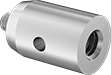
High-Precision Male-Female Round Standoffs
 |
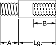 |
Lg. | OD | Thread Lg. (A) | Min. Thread Lg. (B) | Through-Hole Dia. | Each | |||
|---|---|---|---|---|---|---|---|---|
Corrosion-Resistant 18-8 Stainless Steel | ||||||||
8-32 | ||||||||
| 3/4" | 1/2" | 3/16" | 9/32" | 1/8" | 94033A416 | 00000 | ||
| 1" | 1/2" | 3/16" | 9/32" | 1/8" | 94033A421 | 0000 | ||
| 1 1/2" | 1/2" | 3/16" | 9/32" | 1/8" | 94033A426 | 0000 | ||
| 2" | 1/2" | 3/16" | 9/32" | 1/8" | 94033A432 | 0000 | ||
| 3" | 1/2" | 3/16" | 9/32" | 1/8" | 94033A437 | 0000 | ||
| 4" | 1/2" | 3/16" | 9/32" | 1/8" | 94033A444 | 0000 | ||
| 6" | 1/2" | 3/16" | 9/32" | 1/8" | 94033A449 | 00000 | ||
| 8" | 1/2" | 3/16" | 9/32" | 1/8" | 94033A453 | 00000 | ||
| 10" | 1/2" | 3/16" | 9/32" | 1/8" | 94033A455 | 00000 | ||
| 12" | 1/2" | 3/16" | 9/32" | 1/8" | 94033A460 | 00000 | ||
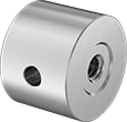
High-Precision Female Round Standoffs
 |
 |
Fully Threaded |
 |
Threaded on Both Ends |
Create exact spacing between male-threaded components in tight-tolerance assemblies, such as laser systems and optical equipment. If you need extra leverage during tightening, you can insert a rod into the through hole. Also known as pillar posts.
Corrosion-Resistant 18-8 Stainless Steel—The choice for wet and outdoor environments, these standoffs resist rusting. They're strong enough for most jobs, but won't withstand stress as well as steel.
Lg. | OD | Threading | Thread Lg. | Min. Thread Lg. | Through-Hole Dia. | Each | |||
|---|---|---|---|---|---|---|---|---|---|
Corrosion-Resistant 18-8 Stainless Steel | |||||||||
1/4"-20 | |||||||||
| 1/2" | 1" | Fully Threaded | 1/2" | — | 3/16" | 93322A350 | 000000 | ||
| 3/4" | 1" | Fully Threaded | 3/4" | — | 3/16" | 93322A380 | 00000 | ||
| 1" | 1" | Threaded on Both Ends | — | 3/8" | 3/16" | 93322A404 | 00000 | ||
| 1 1/2" | 1" | Threaded on Both Ends | — | 3/8" | 3/16" | 93322A416 | 00000 | ||
| 3" | 1" | Threaded on Both Ends | — | 3/8" | 3/16" | 93322A422 | 00000 | ||
| 4" | 1" | Threaded on Both Ends | — | 3/8" | 3/16" | 93322A430 | 00000 | ||
| 6" | 1" | Threaded on Both Ends | — | 3/8" | 3/16" | 93322A446 | 00000 | ||
| 12" | 1" | Threaded on Both Ends | — | 3/8" | 3/16" | 93322A460 | 000000 | ||
Jack Posts
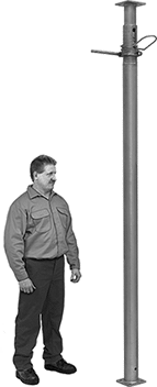 |
These steel jack posts provide temporary or permanent support for beams and joists. Mounting holes in the top and bottom plates let you fasten them in place for a secure installation.
Locking-Pin Adjustment—To adjust the height of locking-pin jack posts, extend the post to the approximate height needed and insert the locking pin through the hole to secure. Then turn the threaded handle counterclockwise to raise it up to 6" for more precise height adjustments.
Locking-Ring Adjustment—To adjust the height of locking-ring jack posts, slide the safety lock into the notch to secure at the approximate height needed. Then turn the 10" long handle for final height adjustments.
Ht. | Wt. Cap. | Base | Top Plate | |||||||||||||
|---|---|---|---|---|---|---|---|---|---|---|---|---|---|---|---|---|
Min. | Max. | @ Min. Ht. | @ Max. Ht. | Material | Wd. | Dp. | Wd. | Dp. | Mounting Hole Dia. (No. of) | Mounting Fasteners Included | Ctr.-to-Ctr. Adjustments | Handle Lg. | Each | |||
Locking-Pin Adjustment | ||||||||||||||||
| 78" | 138" | 6,400 lb. @ 78" | 3,800 lb. @ 138" | Steel | 4 3/4" | 4 3/4" | 4 3/4" | 4 3/4" | 9/16" (8) | No | 6" | — | 2929T15 | 0000000 | ||
| 120" | 216" | 9,300 lb. @ 120" | 2,700 lb. @ 216" | Steel | 4 3/4" | 4 3/4" | 4 3/4" | 4 3/4" | 9/16" (8) | No | 6" | — | 2929T16 | 000000 | ||
Locking-Ring Adjustment | ||||||||||||||||
| 16" | 24" | 18,000 lb. @ 16" | 18,000 lb. @ 24" | Steel | 4" | 4" | 4" | 4" | 3/8" (4), 5/8" (4) | No | 4" | 10" | 2946T5 | 000000 | ||
| 25" | 41" | 18,000 lb. @ 25" | 17,000 lb. @ 41" | Steel | 4" | 4" | 4" | 4" | 3/8" (4), 5/8" (4) | No | 4" | 10" | 2946T4 | 000000 | ||
| 40" | 64" | 18,000 lb. @ 40" | 17,000 lb. @ 64" | Steel | 4" | 4" | 4" | 4" | 3/8" (4), 5/8" (4) | No | 4" | 10" | 2946T3 | 000000 | ||
| 68" | 100" | 17,000 lb. @ 68" | 14,000 lb. @ 100" | Steel | 4" | 4" | 4" | 4" | 3/8" (4), 5/8" (4) | No | 4" | 10" | 2946T1 | 000000 | ||
