


Filter by
Material
Overall Height
Export Control Classification Number (ECCN)
DFARS Specialty Metals
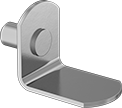
Shelf Supports for Cabinets and Bookcases
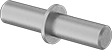 | 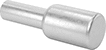 | 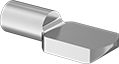 | 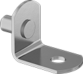 | 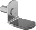 |
Style A | Style B | Style C | Style D | Style E |
 |  | 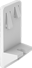 | 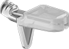 | |
Style F | Style G | Style H | Style J |
Peg | ||||||||||||||
|---|---|---|---|---|---|---|---|---|---|---|---|---|---|---|
Style | Overall Wd. | Overall Dia. | Projection | Wt. Cap. per Four Supports, lb. | Dia. | Dp. | No. of | Color | Features | Pkg. Qty. | Pkg. | |||
Push In | ||||||||||||||
Galvanized Steel | ||||||||||||||
| A | — | 3/16" | 5/16" | 130 | 1/8" | 5/16" | 1 | — | — | 50 | 1741A21 | 00000 | ||
| B | — | 5/16" | 3/8" | Not Rated | 3/16" | 5/16" | 1 | — | Plastic Sleeve | 50 | 1741A37 | 0000 | ||
Brass-Plated Steel | ||||||||||||||
| C | 5/16" | — | 7/16" | 175 | 3/16" | 3/8" | 1 | — | — | 50 | 1741A24 | 0000 | ||
| C | 5/16" | — | 7/16" | 175 | 3/16" | 3/8" | 1 | — | Antislip Fin | 50 | 1741A26 | 0000 | ||
| D | 1/2" | — | 3/4" | 40 | 3/16" | 5/16" | 1 | — | — | 25 | 1741A29 | 0000 | ||
| D | 1/2" | — | 3/4" | 40 | 1/4" | 7/16" | 1 | — | — | 50 | 1741A12 | 00000 | ||
| E | 1/2" | — | 3/4" | 40 | 3/16" | 7/16" | 1 | — | Nonscratching Pad | 25 | 1741A32 | 00000 | ||
| E | 1/2" | — | 3/4" | 40 | 1/4" | 7/16" | 1 | — | Nonscratching Pad | 25 | 1741A33 | 00000 | ||
| F | 1/2" | — | 3/4" | 40 | 3/16" | 5/16" | 1 | — | — | 25 | 1741A27 | 0000 | ||
Nickel-Plated Steel | ||||||||||||||
| B | — | 3/16" | 5/16" | 130 | 1/8" | 5/16" | 1 | — | — | 50 | 1741A22 | 0000 | ||
| C | 5/16" | — | 7/16" | 175 | 3/16" | 3/8" | 1 | — | — | 50 | 1741A23 | 0000 | ||
| C | 5/16" | — | 7/16" | 175 | 3/16" | 3/8" | 1 | — | Antislip Fin | 50 | 1741A25 | 0000 | ||
| C | 7/16" | — | 9/16" | 220 | 9/32" | 3/8" | 1 | — | — | 50 | 1741A34 | 0000 | ||
| D | 1/2" | — | 3/4" | 40 | 3/16" | 5/16" | 1 | — | — | 25 | 1741A31 | 0000 | ||
| D | 1/2" | — | 3/4" | 40 | 3/16" | 5/16" | 1 | — | — | 50 | 1741A13 | 00000 | ||
| D | 1/2" | — | 3/4" | 40 | 1/4" | 7/16" | 1 | — | — | 50 | 1741A11 | 00000 | ||
| F | 1/2" | — | 3/4" | 40 | 3/16" | 5/16" | 1 | — | — | 25 | 1741A28 | 00000 | ||
Nickel-Plated Zinc Alloy | ||||||||||||||
| J | 7/16" | — | 9/16" | 55 | 3/16" | 5/16" | 1 | — | Nonscratching Pad, Ribbed Peg | 25 | 1741A36 | 00000 | ||
Plastic | ||||||||||||||
| G | 5/8" | — | 5/8" | 40 | 3/16" | 3/8" | 1 | Brown | — | 50 | 1741A19 | 00000 | ||
| H | 1 1/16" | — | 11/16" | 500 | 3/16" | 5/16" | 2 | White | — | 50 | 1741A35 | 00000 | ||
High-Precision Index Plungers
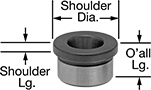
Mating Locating Pins and Hole Liners
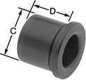
Hole Liners
 |
Shank | Shoulder | Tolerance | |||||||||||||
|---|---|---|---|---|---|---|---|---|---|---|---|---|---|---|---|
For Pin Head Dia. | ID | Dia. (C) | Ht. (D) | Dia. | Ht. | Overall Ht. | Shank Dia. | Shank Ht. | ID | Material | Hardness | Each | |||
For Tapered-Head Pins | |||||||||||||||
| 1/4" | 1/4" | 1/2" | 3/8" | 0.625" | 0.094" | 0.469" | -0.0003" to 0" | -0.0156" to 0.0156" | 0" to 0.0004" | Steel | Rockwell C60 to Rockwell C64 | 31445A116 | 000000 | ||
| 5/16" | 5/16" | 1/2" | 3/8" | 0.625" | 0.094" | 0.469" | -0.0003" to 0" | -0.0156" to 0.0156" | 0" to 0.0004" | Steel | Rockwell C60 to Rockwell C64 | 31445A117 | 00000 | ||
| 3/8" | 3/8" | 5/8" | 1/2" | 0.750" | 0.094" | 0.594" | -0.0003" to 0" | -0.0156" to 0.0156" | 0" to 0.0004" | Steel | Rockwell C60 to Rockwell C64 | 31445A118 | 00000 | ||
| 1/2" | 1/2" | 3/4" | 5/8" | 0.875" | 0.094" | 0.719" | -0.0003" to 0" | -0.0156" to 0.0156" | 0" to 0.0004" | Steel | Rockwell C60 to Rockwell C64 | 31445A119 | 00000 | ||
| 6 mm | 6 mm | 10 mm | 7 mm | 13.000 mm | 3.000 mm | 10.000 mm | 0.023 mm to 0.032 mm | -0.254 mm to 0.254 mm | 0 mm to 0.0102 mm | Steel | Rockwell C58 to Rockwell C62 | 3064N24 | 00000 | ||
| 8 mm | 8 mm | 12 mm | 7 mm | 15.000 mm | 3.000 mm | 10.000 mm | 0.028 mm to 0.039 mm | -0.254 mm to 0.254 mm | 0 mm to 0.0102 mm | Steel | Rockwell C58 to Rockwell C62 | 3064N25 | 00000 | ||
| 10 mm | 10 mm | 15 mm | 9 mm | 18.000 mm | 3.000 mm | 12.000 mm | 0.028 mm to 0.039 mm | -0.254 mm to 0.254 mm | 0 mm to 0.0102 mm | Steel | Rockwell C58 to Rockwell C62 | 3064N26 | 00000 | ||
| 12 mm | 12 mm | 18 mm | 12 mm | 22.000 mm | 3.000 mm | 15.000 mm | 0.028 mm to 0.039 mm | -0.254 mm to 0.254 mm | 0 mm to 0.0102 mm | Steel | Rockwell C58 to Rockwell C62 | 3064N27 | 00000 | ||
For Diamond- and Round-Head Pins | |||||||||||||||
| 1/4" | 1/4" | 13/32" | 7/16" | 0.563" | 0.063" | 0.500" | -0.0003" to 0" | — | 0.0001" to 0.0005" | Steel | Rockwell C50 to Rockwell C62 | 31335A51 | 00000 | ||
| 5/16" | 5/16" | 1/2" | 7/16" | 0.625" | 0.063" | 0.500" | -0.0003" to 0" | — | 0.0001" to 0.0005" | Steel | Rockwell C50 to Rockwell C62 | 31335A52 | 00000 | ||
| 3/8" | 3/8" | 5/8" | 7/16" | 0.750" | 0.063" | 0.500" | -0.0003" to 0" | — | 0.0001" to 0.0005" | Steel | Rockwell C50 to Rockwell C62 | 31335A53 | 00000 | ||
| 1/2" | 1/2" | 3/4" | 1/2" | 0.875" | 0.063" | 0.562" | -0.0003" to 0" | — | 0.0001" to 0.0005" | Steel | Rockwell C50 to Rockwell C62 | 31335A54 | 00000 | ||
| 5/8" | 5/8" | 7/8" | 1/2" | 1.000" | 0.125" | 0.625" | -0.0003" to 0" | — | 0.0002" to 0.0006" | Steel | Rockwell C50 to Rockwell C62 | 31335A21 | 00000 | ||
| 3/4" | 3/4" | 1" | 1/2" | 1.125" | 0.125" | 0.625" | -0.0003" to 0" | — | 0.0002" to 0.0006" | Steel | Rockwell C50 to Rockwell C62 | 31335A55 | 00000 | ||
| 1" | 1" | 1 3/8" | 11/16" | 1.500" | 0.125" | 0.812" | -0.0003" to 0" | — | 0.0002" to 0.0006" | Steel | Rockwell C50 to Rockwell C62 | 31335A22 | 00000 | ||
| 6 mm | 6 mm | 10 mm | 8 mm | 13.000 mm | 2.000 mm | 10.000 mm | 0.023 mm to 0.032 mm | -0.254 mm to 0.254 mm | 0 mm to 0.0102 mm | Steel | Rockwell C58 to Rockwell C62 | 3064N28 | 00000 | ||
| 8 mm | 8 mm | 12 mm | 8 mm | 15.000 mm | 2.000 mm | 10.000 mm | 0.028 mm to 0.039 mm | -0.254 mm to 0.254 mm | 0 mm to 0.0102 mm | Steel | Rockwell C58 to Rockwell C62 | 3064N29 | 00000 | ||
| 10 mm | 10 mm | 15 mm | 10 mm | 18.000 mm | 2.000 mm | 12.000 mm | 0.028 mm to 0.039 mm | -0.254 mm to 0.254 mm | 0 mm to 0.0102 mm | Steel | Rockwell C58 to Rockwell C62 | 3064N31 | 00000 | ||
| 12 mm | 12 mm | 18 mm | 10 mm | 22.000 mm | 2.000 mm | 12.000 mm | 0.028 mm to 0.039 mm | -0.254 mm to 0.254 mm | 0 mm to 0.0102 mm | Steel | Rockwell C58 to Rockwell C62 | 3064N32 | 00000 | ||
For Conical-Head Pins | |||||||||||||||
| 7/16" | 3/8" | 1/2" | 1/4" | 0.750" | 0.250" | 0.500" | -0.0003" to 0" | -0.0625" to 0.0625" | -0.01" to 0" | Steel | Rockwell C60 to Rockwell C64 | 31335A61 | 00000 | ||
| 11/16" | 5/8" | 3/4" | 3/8" | 1.000" | 0.375" | 0.750" | -0.0003" to 0" | -0.0625" to 0.0625" | -0.014" to -0.004" | Steel | Rockwell C60 to Rockwell C64 | 31335A62 | 00000 | ||
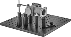
Fixturing for Parts Inspection
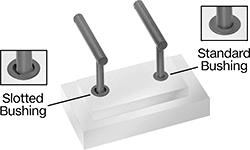
Slotted Bushings
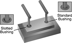 |
When locating a workpiece using through-hole alignment pins (sold separately), use one of these bushings and one standard bushing to prevent the pins from binding in your fixture. One pin sits in the standard drill bushing for tight-tolerance locating in all directions, and the other pin sits in the slotted bushing for tight-tolerance locating in only one direction. This functionality is similar to the combination of round and diamond-head locating pins. Press these bushings into a drilled hole for permanent installation. They’re also known as slotted locator bushings.
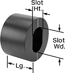
Slotted Bushings with Etched Line—Check the position of the markings to make sure your bushings are aligned.
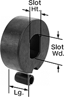
Slotted Bushings with Spring Pin—A spring pin helps you align bushings and keep them from rotating. To mount in your fixture, drill one hole for the spring pin, then another for the bushing.
Slot | Tolerance | ||||||||||||
|---|---|---|---|---|---|---|---|---|---|---|---|---|---|
For Pin Dia. | Ht. | Wd. | Lg. | OD | Slot Ht. | OD | Hardness | Material | Includes | Each | |||
Slotted Bushings with Etched Line | |||||||||||||
 | |||||||||||||
| 1/8" | 1/8" | 1/4" | 1/2" | 3/8" | 0.0001" to 0.0007" | 0.0001" to 0.0004" | Rockwell C58 | Black-Oxide Steel | — | 3322N11 | 000000 | ||
| 3/16" | 3/16" | 3/8" | 1/2" | 1/2" | 0.0001" to 0.0007" | 0.0001" to 0.0004" | Rockwell C58 | Black-Oxide Steel | — | 3322N12 | 00000 | ||
| 0.1925" | 0.1935" | 3/8" | 1/2" | 1/2" | 0.0001" to 0.0006" | 0.0001" to 0.0004" | Rockwell C58 | Black-Oxide Steel | — | 3322N13 | 00000 | ||
| 1/4" | 1/4" | 3/8" | 1/2" | 3/4" | 0.0001" to 0.0007" | 0.0001" to 0.0004" | Rockwell C58 | Black-Oxide Steel | — | 3322N14 | 00000 | ||
| 0.257" | 0.257" | 3/8" | 1/2" | 3/4" | 0.0001" to 0.0007" | 0.0001" to 0.0004" | Rockwell C58 | Black-Oxide Steel | — | 3322N15 | 00000 | ||
| 5/16" | 5/16" | 7/16" | 1/2" | 3/4" | 0.0001" to 0.0007" | 0.0001" to 0.0004" | Rockwell C58 | Black-Oxide Steel | — | 3322N16 | 00000 | ||
| 3/8" | 3/8" | 1/2" | 1/2" | 1" | 0.0001" to 0.0007" | 0.0001" to 0.0004" | Rockwell C58 | Black-Oxide Steel | — | 3322N17 | 00000 | ||
| 1/2" | 1/2" | 5/8" | 1/2" | 1" | 0.0001" to 0.0007" | 0.0001" to 0.0004" | Rockwell C58 | Black-Oxide Steel | — | 3322N18 | 00000 | ||
| 5/8" | 5/8" | 3/4" | 1" | 1 1/4" | 0.0001" to 0.0007" | 0.0001" to 0.0004" | Rockwell C58 | Black-Oxide Steel | — | 3322N19 | 00000 | ||
| 3/4" | 3/4" | 7/8" | 1" | 1 1/2" | 0.0001" to 0.001" | 0.0001" to 0.0004" | Rockwell C58 | Black-Oxide Steel | — | 3322N21 | 00000 | ||
Slotted Bushings with Spring Pin | |||||||||||||
 | |||||||||||||
| 3/16" | 3/16" | 5/16" | 13/32" | 3/4" | 0.0001" to 0.0007" | 0.0001" to 0.0004" | Rockwell C58 | Black-Oxide Steel | 3/16" Slotted Spring Pin | 3322N31 | 00000 | ||
| 1/4" | 1/4" | 3/8" | 13/32" | 3/4" | 0.0001" to 0.0007" | 0.0001" to 0.0004" | Rockwell C58 | Black-Oxide Steel | 3/16" Slotted Spring Pin | 3322N32 | 00000 | ||
| 1/4" | 1/4" | 3/8" | 13/32" | 1" | 0.0001" to 0.0007" | 0.0001" to 0.0004" | Rockwell C58 | Black-Oxide Steel | 3/16" Slotted Spring Pin | 3322N33 | 00000 | ||
| 5/16" | 5/16" | 7/16" | 13/32" | 1" | 0.0001" to 0.0007" | 0.0001" to 0.0004" | Rockwell C58 | Black-Oxide Steel | 3/16" Slotted Spring Pin | 3322N34 | 00000 | ||
| 3/8" | 3/8" | 1/2" | 13/32" | 1" | 0.0001" to 0.0007" | 0.0001" to 0.0004" | Rockwell C58 | Black-Oxide Steel | 3/16" Slotted Spring Pin | 3322N35 | 00000 | ||
| 1/2" | 1/2" | 5/8" | 13/32" | 1" | 0.0001" to 0.0007" | 0.0001" to 0.0004" | Rockwell C58 | Black-Oxide Steel | 3/16" Slotted Spring Pin | 3322N36 | 00000 | ||
| 1/2" | 1/2" | 5/8" | 29/32" | 1" | 0.0001" to 0.0007" | 0.0001" to 0.0004" | Rockwell C58 | Black-Oxide Steel | 3/16" Slotted Spring Pin | 3322N37 | 00000 | ||
| 5/8" | 5/8" | 3/4" | 29/32" | 1 1/4" | 0.0001" to 0.0007" | 0.0001" to 0.0004" | Rockwell C58 | Black-Oxide Steel | 3/16" Slotted Spring Pin | 3322N38 | 00000 | ||
| 3/4" | 3/4" | 13/16" | 1" | 1 1/2" | 0.0001" to 0.0007" | 0.0001" to 0.0004" | Rockwell C58 | Black-Oxide Steel | 3/16" Slotted Spring Pin | 3322N39 | 00000 | ||
| 7/8" | 7/8" | 1" | 1" | 1 1/2" | 0.0001" to 0.0007" | 0.0001" to 0.0004" | Rockwell C58 | Black-Oxide Steel | 3/16" Slotted Spring Pin | 3322N41 | 00000 | ||
| 1" | 1" | 1 1/16" | 1" | 1 1/2" | 0.0001" to 0.0007" | 0.0001" to 0.0004" | Rockwell C58 | Black-Oxide Steel | 3/16" Slotted Spring Pin | 3322N42 | 00000 | ||
| 6 mm | 6 mm | 9 mm | 9 mm | 20 mm | 0.00 mm to 0.03 mm | 0.0025 mm to 0.0102 mm | Rockwell C58 | Black-Oxide Steel | 5 mm Slotted Spring Pin | 3322N43 | 00000 | ||
| 8 mm | 8 mm | 11 mm | 9 mm | 24 mm | 0.00 mm to 0.03 mm | 0.0025 mm to 0.0102 mm | Rockwell C58 | Black-Oxide Steel | 5 mm Slotted Spring Pin | 3322N44 | 00000 | ||
| 10 mm | 10 mm | 13 mm | 9 mm | 24 mm | 0.00 mm to 0.03 mm | 0.0025 mm to 0.0102 mm | Rockwell C58 | Black-Oxide Steel | 5 mm Slotted Spring Pin | 3322N45 | 00000 | ||
| 12 mm | 12 mm | 15 mm | 14 mm | 24 mm | 0.00 mm to 0.03 mm | 0.0025 mm to 0.0102 mm | Rockwell C58 | Black-Oxide Steel | 5 mm Slotted Spring Pin | 3322N46 | 00000 | ||
| 16 mm | 16 mm | 18 mm | 12 mm | 30 mm | 0.00 mm to 0.03 mm | 0.0025 mm to 0.0102 mm | Rockwell C58 | Black-Oxide Steel | 5 mm Slotted Spring Pin | 3322N47 | 00000 | ||
| 20 mm | 20 mm | 22 mm | 19 mm | 36 mm | 0.00 mm to 0.03 mm | 0.0025 mm to 0.0102 mm | Rockwell C58 | Black-Oxide Steel | 5 mm Slotted Spring Pin | 3322N48 | 00000 | ||
| 25 mm | 25 mm | 27 mm | 19 mm | 40 mm | 0.00 mm to 0.03 mm | 0.0025 mm to 0.0102 mm | Rockwell C58 | Black-Oxide Steel | 5 mm Slotted Spring Pin | 3322N49 | 00000 | ||
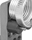
Strong-Hold Slotted Bushings for Plastic
 | 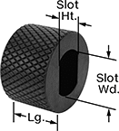 |
With a knurled surface, these bushings grip plastic workpieces tightly so they don't wobble or slip. Use them to prevent through-hole alignment pins (sold separately) from binding while locating workpieces. Your first pin sits in one of these slotted bushings for precise locating in one direction. The second pin sits in a standard bushing for locating in every direction. This setup is similar to the pairing of round and diamond-head locating pins. They're also known as slotted locator bushings.
Slot | Tolerance | ||||||||||||
|---|---|---|---|---|---|---|---|---|---|---|---|---|---|
For Pin Dia. | Ht. | Wd. | Lg. | OD | Slot Ht. | OD | Hardness | Material | Surface Texture | Each | |||
| 3/16" | 3/16" | 5/16" | 1/2" | 0.565" | 0" to 0.001" | -0.005" to 0.005" | Rockwell C58 | Black-Oxide Steel | Knurled | 8610N21 | 000000 | ||
| 1/4" | 1/4" | 3/8" | 1/2" | 0.64" | 0" to 0.001" | -0.005" to 0.005" | Rockwell C58 | Black-Oxide Steel | Knurled | 8610N41 | 00000 | ||
| 5/16" | 5/16" | 7/16" | 1/2" | 0.765" | 0" to 0.001" | -0.005" to 0.005" | Rockwell C58 | Black-Oxide Steel | Knurled | 8610N51 | 00000 | ||
| 3/8" | 3/8" | 1/2" | 1/2" | 0.89" | 0" to 0.001" | -0.005" to 0.005" | Rockwell C58 | Black-Oxide Steel | Knurled | 8610N71 | 00000 | ||
| 1/2" | 1/2" | 5/8" | 1/2" | 1.015" | 0" to 0.001" | -0.005" to 0.005" | Rockwell C58 | Black-Oxide Steel | Knurled | 8610N81 | 00000 | ||
| 1/2" | 1/2" | 5/8" | 1" | 1.015" | 0" to 0.001" | -0.005" to 0.005" | Rockwell C58 | Black-Oxide Steel | Knurled | 8610N82 | 00000 | ||
