


Filter by
System of Measurement
Diameter
End Shape
End Type

Steel Grade
Shaft Type
Head Diameter
Minimum Hardness
Hardness
DFARS Specialty Metals
Export Control Classification Number (ECCN)
Double Shear Breaking Strength
Thread Size
Body Shape

Cotter Pin Included
Tolerance Rating
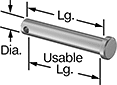
Clevis Pins
Steel
 |
Cotter Pin Not Included |
Carbon Steel—Stronger than stainless steel, these pins won't deform from stress and vibration. They perform best in dry environments since moisture will cause them to rust.
Zinc-Plated Carbon Steel—These pins withstand occasional exposure to moisture. However, since friction from moving parts can wear away the finish, they're not ideal for wet environments. While not nearly as corrosion resistant as stainless steel, they are stronger and won’t deform under stress.
Head | |||||||||||
|---|---|---|---|---|---|---|---|---|---|---|---|
Usable Lg. | Dia. Tolerance | For Max. Cotter Pin Dia. | Min. Hardness | Lg. | Dia. | Ht. | Pkg. Qty. | Pkg. | |||
Carbon Steel | |||||||||||
9/16" Diameter | |||||||||||
| 1 3/4" | -0.010" to -0.005" | 1/8" | Rockwell B63 | 2" | 13/16" | 7/32" | 1 | 98306A442 | 00000 | ||
| 2 1/4" | -0.010" to -0.005" | 1/8" | Rockwell B63 | 2 1/2" | 13/16" | 7/32" | 5 | 98306A444 | 00000 | ||
| 2 3/4" | -0.010" to -0.005" | 1/8" | Rockwell B63 | 3" | 13/16" | 7/32" | 5 | 98306A446 | 00000 | ||
| 3 3/4" | -0.010" to -0.005" | 5/32" | Rockwell B63 | 4" | 13/16" | 7/32" | 5 | 98306A617 | 00000 | ||
Zinc-Plated Carbon Steel | |||||||||||
9/16" Diameter | |||||||||||
| 1 3/4" | -0.009" to -0.004" | 1/8" | Rockwell B63 | 2" | 13/16" | 5/32" | 5 | 97245A765 | 00000 | ||
| 2 1/4" | -0.009" to -0.004" | 1/8" | Rockwell B63 | 2 1/2" | 13/16" | 13/64" | 5 | 97245A766 | 00000 | ||
| 2 3/4" | -0.009" to -0.004" | 1/8" | Rockwell B63 | 3" | 13/16" | 13/64" | 5 | 97245A767 | 00000 | ||
| 3 3/4" | -0.009" to -0.004" | 1/8" | Rockwell B63 | 4" | 13/16" | 13/64" | 5 | 97245A768 | 00000 | ||
Corrosion-Resistant Stainless Steel
|
Cotter Pin Not Included |
18-8 Stainless Steel—The choice for wet and outdoor environments, these pins resist rusting. They're strong enough to fasten most components but won't withstand stress and vibration as well as steel.
Head | |||||||||||
|---|---|---|---|---|---|---|---|---|---|---|---|
Usable Lg. | Dia. Tolerance | For Max. Cotter Pin Dia. | Min. Hardness | Lg. | Dia. | Ht. | Pkg. Qty. | Pkg. | |||
18-8 Stainless Steel | |||||||||||
9/16" Diameter | |||||||||||
| 1 3/4" | -0.010" to -0.005" | 1/8" | Rockwell B80 | 2" | 13/16" | 7/32" | 1 | 92390A441 | 000000 | ||
| 2 1/4" | -0.010" to -0.005" | 1/8" | Rockwell B80 | 2 1/2" | 13/16" | 7/32" | 1 | 92390A445 | 00000 | ||
| 2 3/4" | -0.010" to -0.005" | 1/8" | Rockwell B80 | 3" | 13/16" | 7/32" | 1 | 92390A449 | 00000 | ||
Dowel Pins
Steel
Lg. | Dia. Tolerance | Double Shear Breaking Strength | Min. Hardness | Pkg. Qty. | Pkg. | |||
|---|---|---|---|---|---|---|---|---|
High-Strength Alloy Steel | ||||||||
9/16" Diameter | ||||||||
| 3/4" | 0.0001" to 0.0003" | Not Rated | Rockwell C50 | 1 | 98381A768 | 00000 | ||
| 1" | 0.0001" to 0.0003" | Not Rated | Rockwell C50 | 1 | 98381A040 | 0000 | ||
| 1 1/2" | 0.0001" to 0.0003" | Not Rated | Rockwell C50 | 1 | 98381A041 | 0000 | ||
| 2" | 0.0001" to 0.0003" | Not Rated | Rockwell C50 | 1 | 98381A042 | 00000 | ||
| 2 1/2" | 0.0001" to 0.0003" | Not Rated | Rockwell C50 | 1 | 98381A779 | 00000 | ||
| 3" | 0.0001" to 0.0003" | Not Rated | Rockwell C50 | 1 | 98381A043 | 00000 | ||
| 4" | 0.0001" to 0.0003" | Not Rated | Rockwell C50 | 1 | 98381A044 | 00000 | ||
Dowel Pin Stock
 |
Dia. | Dia. Tolerance | Lg. | Min. Hardness | Each | |||
|---|---|---|---|---|---|---|---|
4140 Alloy Steel | |||||||
| 9/16" | 0.0001" to 0.0003" | 12" | Rockwell C15 | 98912A580 | 000000 | ||
M2 High-Speed Tool Steel | |||||||
| 9/16" | -0.002" to 0.002" | 12" | Rockwell C60 | 99585A500 | 00000 | ||
18-8 Stainless Steel | |||||||
| 9/16" | 0.0001" to 0.0003" | 12" | Rockwell C2 | 95609A380 | 00000 | ||
316 Stainless Steel | |||||||
| 9/16" | 0.0001" to 0.0003" | 12" | Rockwell C9 | 91958A118 | 00000 | ||
416 Stainless Steel | |||||||
| 9/16" | 0.0001" to 0.0003" | 12" | Rockwell C1 | 95384A118 | 00000 | ||
17-4 PH Stainless Steel | |||||||
| 9/16" | 0.0001" to 0.0003" | 12" | Rockwell C28 | 98312A118 | 00000 | ||
Ejector Pins
Alignment Pins
Core Pins
Double-Tapered-End Alignment Pins
Body | |||||||||
|---|---|---|---|---|---|---|---|---|---|
Point Dia. | Taper Lg. | Dia. | Overall Lg. | Shape | Texture | Each | |||
Steel | |||||||||
| 1/4" | 2" | 9/16" | 6" | Round | Smooth | 6053A2 | 000000 | ||
High-Strength Anchors for Block and Brick
 |
Ultimate Strength, lbf | |||||||||||
|---|---|---|---|---|---|---|---|---|---|---|---|
Thread Size | Lg. | Drill Bit Size | Min. Installation Dp. | Material | Pull-Out | Shear | Conditions Tested In | Pkg. Qty. | Pkg. | ||
| 5/16"-18 | 1 1/2" | 9/16" | 1 1/2" | Zinc | 2,600 | 3,280 | 3,000 psi Concrete | 10 | 92915A120 | 000000 | |
