


Filter by
System of Measurement
Thread Size
Shaft Diameter
Drive Style
Material
Thread Type

Mount Type
Specifications Met
End Type
Threading
Thread Direction
End Shape
REACH
Export Control Classification Number (ECCN)
DFARS Specialty Metals
Single-End Studs
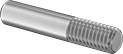 |
Screw the threaded end of these studs into a tapped hole, and use the unthreaded end as a pivot point, hinge, shaft, or locator pin.
Steel—These studs are steel for strength and wear resistance. They’re best for dry environments since moisture will cause them to rust. All meet ISO 2342 (formerly DIN 427), an international standard for fastener dimensions.
Shaft, mm | |||||||||||||
|---|---|---|---|---|---|---|---|---|---|---|---|---|---|
Lg., mm | Thread Lg., mm | Lg. | Dia. | Dia. Tolerance | Tensile Strength | Hardness | Drive Style | Specs. Met | Pkg. Qty. | Pkg. | |||
Steel | |||||||||||||
M3 × 0.5 mm | |||||||||||||
| 6 | 3.6 | 2.4 | 3 | -0.14 to 0 | Not Rated | Rockwell B75 | Slotted | DIN 427, ISO 2342 | 25 | 97493A111 | 000000 | ||
| 10 | 3.6 | 6.4 | 3 | -0.14 to 0 | Not Rated | Rockwell B75 | Slotted | DIN 427, ISO 2342 | 25 | 97493A112 | 00000 | ||
| 12 | 3.6 | 8.4 | 3 | -0.14 to 0 | Not Rated | Rockwell B75 | Slotted | DIN 427, ISO 2342 | 25 | 97493A113 | 00000 | ||
| 16 | 3.5 | 12.5 | 3 | -0.14 to 0 | Not Rated | Rockwell B75 | Slotted | DIN 427, ISO 2342 | 10 | 97493A151 | 00000 | ||
| 18 | 3.5 | 14.5 | 3 | -0.14 to 0 | Not Rated | Rockwell B75 | Slotted | DIN 427, ISO 2342 | 10 | 97493A152 | 00000 | ||
Vented Pull-Out Dowel Pins
Flat Shaft
The flat side of these pins creates a vent that's less likely to be blocked than a spiral shaft, but doesn’t offer quite as strong of a hold.
18-8 Stainless Steel—The choice for wet and outdoor environments. In addition to resisting rust, these pins also withstand mild chemicals such as cleaners and degreasers. They are strong enough to join most components but won't withstand extreme stress and vibration as well as steel.
Lg., mm | Dia. Tolerance, mm | Thread Size | Double Shear Breaking Strength, lbf | Min. Hardness | Specs. Met | Each | |||
|---|---|---|---|---|---|---|---|---|---|
18-8 Stainless Steel | |||||||||
4 mm Diameter | |||||||||
| 16 | 0.004 to 0.015 | M3 × 0.5 mm | 101,000 | Rockwell C18 | DIN 7979C-m6 | 98432A111 | 00000 | ||
| 20 | 0.004 to 0.015 | M3 × 0.5 mm | 101,000 | Rockwell C18 | DIN 7979C-m6 | 98432A112 | 00000 | ||
5 mm Diameter | |||||||||
| 10 | 0.004 to 0.015 | M3 × 0.5 mm | 101,000 | Rockwell C18 | DIN 7979C-m6 | 98432A113 | 0000 | ||
| 24 | 0.004 to 0.015 | M3 × 0.5 mm | 101,000 | Rockwell C18 | DIN 7979C-m6 | 98432A114 | 00000 | ||
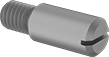
Steel Headless Slotted Precision Shoulder Screws
 |
Shoulder Lg., mm | Thread Size | Thread Lg., mm | Tensile Strength | Specs. Met | Pkg. Qty. | Pkg. | |||
|---|---|---|---|---|---|---|---|---|---|
Alloy Steel | |||||||||
4 mm Diameter Shoulder (-0.03 mm to 0 mm Tolerance) | |||||||||
| 3 | M3 × 0.5 mm | 4.5 | Not Rated | DIN 927 | 10 | 94128A101 | 00000 | ||
| 4 | M3 × 0.5 mm | 4.5 | Not Rated | DIN 927 | 10 | 94128A102 | 0000 | ||
| 5 | M3 × 0.5 mm | 4.5 | Not Rated | DIN 927 | 10 | 94128A103 | 0000 | ||
| 6 | M3 × 0.5 mm | 4.5 | Not Rated | DIN 927 | 10 | 94128A104 | 0000 | ||
| 8 | M3 × 0.5 mm | 4.5 | Not Rated | DIN 927 | 10 | 94128A105 | 0000 | ||
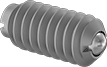
Ball-Nose Spring Plungers
 |
 |
Align, position, and lock moving parts for most machining and assembly tasks. These spring plungers have a spring-loaded ball that compresses when a part presses against it, and then pops out into a notch or groove to hold the part in place. Unlike long-nose spring plungers, the ball rolls easily in and out of position, so they're a great fit for applications that require consistent, smooth movement, such as positioning parts in an assembly line and aligning fixtures and jigs when cutting or drilling.
Spring plungers are available with or without a threadlocker. Those with a threadlocker won't wiggle loose from vibration. Spring plungers without a threadlocker are easier to remove.
440C Stainless Steel Nose—The strongest, most wear-resistant stainless steel noses, these grind against hard metal surfaces without denting or scratching. However, they are not as corrosion resistant as 316 stainless steel.
Nylon Nose—Extra soft to avoid scratching delicate surfaces. Nylon is best for use on soft materials, such as aluminum. It will swell and weaken when exposed to moisture, however, so it should only be used in dry environments.
Nose, mm | Nose Force, lbf | Body | Drive Style | |||||||||
|---|---|---|---|---|---|---|---|---|---|---|---|---|
Thread Size | Extended Lg. | Dia. | Extended | Compressed | Material | Lg., mm | Front | Back | Each | |||
440C Stainless Steel Nose | ||||||||||||
| M3 x 0.5 mm | 0.4 | 1.5 | 0.7 | 1 | 18-8 Stainless Steel | 7 | Spring Plunger Driver | Slotted | 85015A31 | 00000 | ||
| M3 x 0.5 mm | 0.4 | 1.5 | 0.7 | 1 | Black-Oxide Steel | 7 | Spring Plunger Driver | Slotted | 3391A65 | 0000 | ||
Nylon Nose | ||||||||||||
| M3 x 0.5 mm | 0.4 | 1.5 | 0.7 | 1 | 18-8 Stainless Steel | 7 | Spring Plunger Driver | Slotted | 2277A65 | 0000 | ||
| M3 x 0.5 mm | 0.4 | 1.5 | 0.7 | 1 | Steel | 7 | Spring Plunger Driver | Slotted | 2191A25 | 0000 | ||
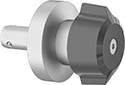
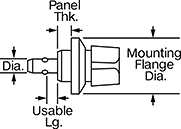
Quick-Release Pins for Blind Holes
Twist Knob
 |  |
Quick-Release Pins | Receptacles | ||||||||||||||
|---|---|---|---|---|---|---|---|---|---|---|---|---|---|---|---|
Dia., mm | Usable Lg., mm | For Panel Thk., mm | Mounting Flange Dia., mm | Double Shear Breaking Strength | Min. Hardness | Handle Color | Handle Material | Ball Material | Mounting Fasteners Included | Each | Each | ||||
Nickel-Plated Carbon Steel | |||||||||||||||
| 10 | 10.5 | 6 to 14 | 34 | Not Rated | Not Rated | Black | Plastic | Stainless Steel | Yes | 97580A312 | 000000 | 99802A212 | 000000 | ||
Press-Fit Studs
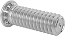 |
Press these studs into a drilled or punched hole with an arbor press or similar pressure tool. Also known as self-clinching studs, ribs under the head hold the stud firmly in place. Length listed is overall length.
Zinc-Plated Steel—The most common choice for areas with occasional exposure to moisture.
18-8 Stainless Steel—The choice for wet and outdoor environments, these studs resist rust. However, they won't hold up to the harsh chemicals that 316 stainless steel can.
Lg., mm | PEM® Part No. | Thread Lg., mm | For Min. Material Thk., mm | For Min. Lg. Between Hole Ctr. and Sheet Edge, mm | For Hole Dia., mm | Hole Size Tolerance, mm | Drill Bit Size, mm | Base Dia., mm | Tensile Strength | Hardness | Pkg. Qty. | Pkg. | |||
|---|---|---|---|---|---|---|---|---|---|---|---|---|---|---|---|
Zinc-Plated Steel | |||||||||||||||
M3 × 0.5 mm | |||||||||||||||
| 6 | FH-M3-6 | 4 | 1.000 | 5.5 | 3 | 0.000 to 0.08 | 3.0 | 5 | Not Rated | Not Rated | 50 | 93580A576 | 00000 | ||
| 8 | FH-M3-8 | 6 | 1.000 | 5.5 | 3 | 0.000 to 0.08 | 3.0 | 5 | Not Rated | Not Rated | 50 | 93580A577 | 0000 | ||
| 10 | FH-M3-10 | 8 | 1.000 | 5.5 | 3 | 0.000 to 0.08 | 3.0 | 5 | Not Rated | Not Rated | 50 | 93580A578 | 0000 | ||
| 12 | FH-M3-12 | 10 | 1.000 | 5.5 | 3 | 0.000 to 0.08 | 3.0 | 5 | Not Rated | Not Rated | 50 | 93580A579 | 0000 | ||
| 15 | FH-M3-15 | 13 | 1.000 | 5.5 | 3 | 0.000 to 0.08 | 3.0 | 5 | Not Rated | Not Rated | 50 | 93580A581 | 0000 | ||
| 18 | FH-M3-18 | 16 | 1.000 | 5.5 | 3 | 0.000 to 0.08 | 3.0 | 5 | Not Rated | Not Rated | 50 | 93580A582 | 0000 | ||
| 20 | FH-M3-20 | 18 | 1.000 | 5.5 | 3 | 0.000 to 0.08 | 3.0 | 5 | Not Rated | Not Rated | 25 | 93580A583 | 0000 | ||
| 25 | FH-M3-25 | 23 | 1.000 | 5.5 | 3 | 0.000 to 0.08 | 3.0 | 5 | Not Rated | Not Rated | 25 | 93580A584 | 0000 | ||
18-8 Stainless Steel | |||||||||||||||
M3 × 0.5 mm | |||||||||||||||
| 6 | FHS-M3-6 | 4 | 1.000 | 5.5 | 3 | 0.000 to 0.08 | 3.0 | 4.2 | Not Rated | Not Rated | 25 | 93580A695 | 0000 | ||
| 8 | FHS-M3-8 | 6 | 1.000 | 5.5 | 3 | 0.000 to 0.08 | 3.0 | 4.2 | Not Rated | Not Rated | 25 | 93580A696 | 0000 | ||
| 10 | FHS-M3-10 | 8 | 1.000 | 5.5 | 3 | 0.000 to 0.08 | 3.0 | 4.2 | Not Rated | Not Rated | 50 | 93580A697 | 0000 | ||
| 12 | FHS-M3-12 | 10 | 1.000 | 5.5 | 3 | 0.000 to 0.08 | 3.0 | 4.2 | Not Rated | Not Rated | 25 | 93580A698 | 0000 | ||
| 15 | FHS-M3-15 | 13 | 1.000 | 5.5 | 3 | 0.000 to 0.08 | 3.0 | 4.2 | Not Rated | Not Rated | 25 | 93580A699 | 0000 | ||
| 18 | FHS-M3-18 | 16 | 1.000 | 5.5 | 3 | 0.000 to 0.08 | 3.0 | 4.2 | Not Rated | Not Rated | 25 | 93580A701 | 0000 | ||
| 20 | FHS-M3-20 | 18 | 1.000 | 5.5 | 3 | 0.000 to 0.08 | 3.0 | 4.2 | Not Rated | Not Rated | 10 | 93580A702 | 0000 | ||
| 25 | FHS-M3-25 | 23 | 1.000 | 5.5 | 3 | 0.000 to 0.08 | 3.0 | 4.2 | Not Rated | Not Rated | 10 | 93580A703 | 0000 | ||
Tapped Rounded Machine Keys
Tolerance, mm | ||||||||||
|---|---|---|---|---|---|---|---|---|---|---|
Lg., mm | Tolerance Rating | Ht. | Wd. | Min. Hardness | Thread Size | Specs. Met | Each | |||
1018-1045 Carbon Steel | ||||||||||
5 mm × 5 mm | ||||||||||
| 20 | Undersized | -0.030 to 0.000 | -0.030 to 0.000 | Not Rated | M3 × 0.5 mm | DIN 6885 | 90164A101 | 00000 | ||
| 25 | Undersized | -0.030 to 0.000 | -0.030 to 0.000 | Not Rated | M3 × 0.5 mm | DIN 6885 | 90164A103 | 0000 | ||
| 40 | Undersized | -0.030 to 0.000 | -0.030 to 0.000 | Not Rated | M3 × 0.5 mm | DIN 6885 | 90164A108 | 0000 | ||
6 mm × 6 mm | ||||||||||
| 20 | Undersized | -0.030 to 0.000 | -0.030 to 0.000 | Not Rated | M3 × 0.5 mm | DIN 6885 | 90164A112 | 0000 | ||
| 25 | Undersized | -0.030 to 0.000 | -0.030 to 0.000 | Not Rated | M3 × 0.5 mm | DIN 6885 | 90164A114 | 0000 | ||
| 30 | Undersized | -0.030 to 0.000 | -0.030 to 0.000 | Not Rated | M3 × 0.5 mm | DIN 6885 | 90164A115 | 0000 | ||
| 32 | Undersized | -0.030 to 0.000 | -0.030 to 0.000 | Not Rated | M3 × 0.5 mm | DIN 6885 | 90164A116 | 0000 | ||
| 50 | Undersized | -0.030 to 0.000 | -0.030 to 0.000 | Not Rated | M3 × 0.5 mm | DIN 6885 | 90164A123 | 0000 | ||
7 mm × 8 mm | ||||||||||
| 20 | Undersized | -0.090 to 0.000 | -0.036 to 0.000 | Not Rated | M3 × 0.5 mm | DIN 6885 | 90164A124 | 0000 | ||
| 28 | Undersized | -0.090 to 0.000 | -0.036 to 0.000 | Not Rated | M3 × 0.5 mm | DIN 6885 | 90164A127 | 0000 | ||
| 30 | Undersized | -0.090 to 0.000 | -0.036 to 0.000 | Not Rated | M3 × 0.5 mm | DIN 6885 | 90164A128 | 0000 | ||
| 32 | Undersized | -0.090 to 0.000 | -0.036 to 0.000 | Not Rated | M3 × 0.5 mm | DIN 6885 | 90164A129 | 0000 | ||
| 36 | Undersized | -0.090 to 0.000 | -0.036 to 0.000 | Not Rated | M3 × 0.5 mm | DIN 6885 | 90164A131 | 0000 | ||
| 40 | Undersized | -0.090 to 0.000 | -0.036 to 0.000 | Not Rated | M3 × 0.5 mm | DIN 6885 | 90164A132 | 0000 | ||
| 45 | Undersized | -0.090 to 0.000 | -0.036 to 0.000 | Not Rated | M3 × 0.5 mm | DIN 6885 | 90164A133 | 0000 | ||
| 50 | Undersized | -0.090 to 0.000 | -0.036 to 0.000 | Not Rated | M3 × 0.5 mm | DIN 6885 | 90164A135 | 0000 | ||
8 mm × 10 mm | ||||||||||
| 20 | Undersized | -0.036 to 0.000 | -0.036 to 0.000 | Not Rated | M3 × 0.5 mm | DIN 6885 | 90164A137 | 0000 | ||
| 30 | Undersized | -0.036 to 0.000 | -0.036 to 0.000 | Not Rated | M3 × 0.5 mm | DIN 6885 | 90164A142 | 0000 | ||
| 36 | Undersized | -0.036 to 0.000 | -0.036 to 0.000 | Not Rated | M3 × 0.5 mm | DIN 6885 | 90164A144 | 0000 | ||
| 40 | Undersized | -0.036 to 0.000 | -0.036 to 0.000 | Not Rated | M3 × 0.5 mm | DIN 6885 | 90164A146 | 0000 | ||
| 50 | Undersized | -0.036 to 0.000 | -0.036 to 0.000 | Not Rated | M3 × 0.5 mm | DIN 6885 | 90164A149 | 0000 | ||
| 56 | Undersized | -0.036 to 0.000 | -0.036 to 0.000 | Not Rated | M3 × 0.5 mm | DIN 6885 | 90164A151 | 0000 | ||
Go/No-Go Threaded Plug Gauges with Handle
Class X Gauge
Double-Ended Taperlock Handle |
Calibration Certificate Traceable to NIST—Gauges with a calibration certificate traceable to NIST were calibrated in a lab. The certificate, sometimes called a test report or long-form certificate, details the tested measurements.
For Metric Class 6H Thread Fit—These metric-threaded gauges are class 6H, which is comparable to the fit of those with Class 2B Unified Standard.
For Thread Fit—Thread fit designates the tightness or looseness of mating threads.
Thread Size | Thread Type | Pitch Dia. Tolerance, mm | Hardness | Material | Features | For Thread Fit | Each | |||
|---|---|---|---|---|---|---|---|---|---|---|
Go/No-Go Gauges | ||||||||||
| M3 × 0.5 mm | Metric | -0.005 to 0.005 | Rockwell C70 | Chrome-Plated Tool Steel | Double-Ended Taperlock Handle | Metric Class 6H | 23585A111 | 0000000 | ||
Go/No-Go Gauges with Calibration Certificate Traceable to NIST | ||||||||||
| M3 × 0.5 mm | Metric | -0.005 to 0.005 | Rockwell C70 | Chrome-Plated Tool Steel | Double-Ended Taperlock Handle | Metric Class 6H | 3206A115 | 000000 | ||
Threaded Plug Gauges
Class X Gauge
Thread Size | Thread Type | Pitch Dia. Tolerance | Hardness | Material | For Thread Fit | Each | |||
|---|---|---|---|---|---|---|---|---|---|
Go Gauges | |||||||||
| M3 × 0.5 mm | Metric | 0" to 0.0002" | Rockwell C70 | Chrome-Plated Tool Steel | Metric Class 6H | 7968N35 | 000000 | ||
Go Gauges with Accuracy Certificate Traceable to NIST | |||||||||
| M3 × 0.5 mm | Metric | 0" to 0.0002" | Rockwell C70 | Chrome-Plated Tool Steel | Metric Class 6H | 7968N125 | 00000 | ||
No-Go Gauges | |||||||||
| M3 × 0.5 mm | Metric | -0.0002" to 0" | Rockwell C70 | Chrome-Plated Tool Steel | Metric Class 6H | 7968N79 | 00000 | ||
No-Go Gauges with Accuracy Certificate Traceable to NIST | |||||||||
| M3 × 0.5 mm | Metric | -0.0002" to 0" | Rockwell C70 | Chrome-Plated Tool Steel | Metric Class 6H | 7968N169 | 00000 | ||
