


Filter by
Pipe Size

For Pipe OD
Overall Width
Handle Style


For Manufacturer
Body Material

Export Control Classification Number (ECCN)
Overall Height
DFARS Specialty Metals
Handle Material
Arm Material
Width
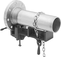
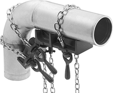
Pipe Welding Clamps
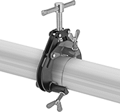 |
External Clamping—Thumb Screw Adjustment |
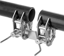 |
External Clamping—Self-Centering |
 |
Internal Clamping—Self-Centering |
For Pipe | Steel Body | Stainless Steel Body | |||||
|---|---|---|---|---|---|---|---|
OD | Size | Each | Each | ||||
External Clamping—Thumb Screw Adjustment | |||||||
| 1" to 3" | 3/4 to 2 1/2 | 2530N31 | 0000000 | ——— | 0 | ||
| 2" to 6" | 2 to 5 | 2530N12 | 000000 | ——— | 0 | ||
| 6" to 14" | 6 to 12 | 2530N33 | 000000 | ——— | 0 | ||
External Clamping—Self-Centering | |||||||
| 1/8" to 3" | 1/8 to 2 1/2 | ——— | 0 | 2530N22 | 0000000 | ||
| 1 1/2" to 5" | 1 1/4 to 4 | ——— | 0 | 2530N23 | 000000 | ||
Internal Clamping—Self-Centering | |||||||
| 2" to 6" | 2 to 5 | ——— | 0 | 2530N15 | 000000 | ||
| 4" to 8" | 3 1/2 to 7 | ——— | 0 | 2530N16 | 000000 | ||
| 6" to 14" | 6 to 14 | ——— | 0 | 2530N17 | 00000000 | ||
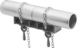
Heavy Duty Chain Pipe Welding Clamps
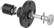
Pipe Flange Alignment Kits
 |
Hand-Crank Alignment |
 |
Ratchet Alignment |
 |
Hydraulic Alignment |
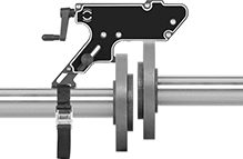
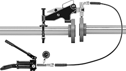
Align flanges on heavy pipes when alignment pins don't fit through the flange holes. Often used for pipefitting, welding, and maintenance, these kits make it possible to correct angular and offset misalignment on a range of pipe sizes.
Choose an alignment mechanism based on how much force you need to move the pipe. If you're not sure, measure the flange hole diameter—it correlates to the pressure class and size of your pipe. Larger pipes typically require more force.
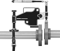
Hand-Crank Alignment—Hand-crank aligners are best for routine maintenance and quick repairs. As you turn the hand crank, it moves the pipe.
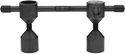
Ratchet Alignment—Ratchet aligners produce four times as much force as hand crank aligners. Position the tool's arm through a flange hole on the pipe you plan to move, and place the lead screw on the edge of the stationary pipe's flange. Wrap the strap around the pipe you plan to move. As you rotate the lead screw with a wrench, the misaligned pipe moves into position.
Hydraulic Alignment—Hydraulic aligners are best for severe misalignment—they generate over twice as much force as ratcheting aligners. Position the tool's arm through the flange hole on the pipe you plan to move, and place the lead screw on the edge of the stationary pipe's flange. Wrap the strap around the pipe you plan to move. As you press down on the hand pump connected to the lead screw, the pipe moves.
Alignment Mechanism | Wt. Cap., lb. | For Min. Flange Hole Dia. | Includes | Container Type | Each | ||
|---|---|---|---|---|---|---|---|
| Hand Crank | 2,400 | 5/8" | Strap | — | 7068N11 | 000000000 | |
| Ratchet | 9,900 | 1" | Socket, Strap, Wrench | Plastic Carrying Case | 7068N12 | 00000000 | |
| Hydraulic | 22,200 | 1 3/8" | Hand Pump with Gauge, Hydraulic Cylinder, Hydraulic Hose, Strap | Plastic Carrying Case | 7068N13 | 00000000 |
Stepped Pipe Flange Aligner Pins
Bench Vise Jaws
For Wilton
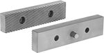 | 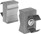 |
Flat Jaw | V-Jaw |
Overall | Mounting | Steel Jaw | ||||||||
|---|---|---|---|---|---|---|---|---|---|---|
For Mfr. Model No. | Jaw Texture | Wd. | Ht. | Thk. | Fasteners Included | Hole Ctr.-to-Ctr. | Each | |||
Flat Jaw | ||||||||||
| 10006, 10056, 300N, 300S | Serrated | 3" | 3/4" | 1/2" | Yes | 2" | 8467A12 | 0000000 | ||
| 10011, 10066, 10200, 350N, 350S, C-0 | Serrated | 3 1/2" | 1 1/4" | 5/8" | Yes | 2 3/8" | 8467A32 | 000000 | ||
| 10016, 10076, 400N, 400S | Serrated | 4" | 1 1/4" | 5/8" | Yes | 2 3/8" | 8467A34 | 000000 | ||
| 10021, 10086, 10225, 450N, 450S, C-1 | Serrated | 4 1/2" | 1 1/4" | 5/8" | Yes | 2 3/8" | 8467A35 | 000000 | ||
| 10026, 10096, 500N, 500S | Serrated | 5" | 1 1/4" | 5/8" | Yes | 2 3/8" | 8467A36 | 000000 | ||
| 10031, 10107, 600N, 600S | Serrated | 6" | 1 1/2" | 1" | Yes | 2 3/8" | 8467A17 | 000000 | ||
| 10036, 10116, 800N, 800S | Serrated | 8" | 1 1/2" | 1" | Yes | 6" | 8467A18 | 000000 | ||
| 10250, C-2 | Serrated | 5" | 1" | 5/8" | Yes | 2 3/8" | 5200A151 | 000000 | ||
| 10275, C-3 | Serrated | 6" | 1 3/8" | 9/16" | Yes | 4" | 5200A779 | 000000 | ||
| 11126, 674 | Serrated | 4 1/2" | 15/16" | 1/2" | Yes | 2 1/2" | 5310A45 | 00000 | ||
| 11127, 675 | Serrated | 5 1/2" | 3/4" | 3/8" | Yes | 2 1/2" | 5310A46 | 00000 | ||
| 11128, 676 | Serrated | 6 1/2" | 3/4" | 7/8" | Yes | 2 1/2" | 5310A47 | 00000 | ||
| 14500, 4500 | Serrated | 5 1/2" | 3/4" | 1/2" | Yes | 3 1/2" | 8467A25 | 00000 | ||
| 1550, 21400, 63187, 745 | Serrated | 5" | 3/4" | 1/2" | Yes | 2 3/8" | 8467A27 | 00000 | ||
| 1560, 21500, 63188, 746 | Serrated | 6" | 1" | 5/8" | Yes | 4" | 8467A28 | 00000 | ||
| 1745, 63199 | Serrated | 4 1/2" | 3/4" | 1/2" | Yes | 2 3/8" | 5344A35 | 000000 | ||
| 1755, 63200 | Serrated | 5 1/2" | 3/4" | 1/2" | Yes | 2 3/8" | 5344A36 | 000000 | ||
| 1765, 63201 | Serrated | 6 1/2" | 1" | 5/8" | Yes | 2 3/8" | 5344A37 | 000000 | ||
| 1780, 1780A, 63202 | Serrated | 8" | 1" | 5/8" | Yes | 4" | 5344A38 | 000000 | ||
| 191, 656HD | Serrated | 6 1/8" | 1" | 1/2" | Yes | 4" | 5310A35 | 00000 | ||
| 21300, 744 | Serrated | 4" | 3/4" | 1/2" | Yes | 2 3/8" | 8467A26 | 00000 | ||
| 21800, 748A | Serrated | 8" | 1" | 1/2" | Yes | 4" | 8467A31 | 00000 | ||
| 63198, 63244, CBV-65, SBV-65 | Serrated | 2 1/2" | 1/2" | 1/4" | Yes | 1 5/8" | 8467A91 | 00000 | ||
| 63247, 63248, CBV-100, SBV-100 | Serrated | 4" | 7/8" | 1/2" | Yes | 2 3/8" | 8467A92 | 00000 | ||
| 63300, WS4 | Serrated | 3 7/8" | 3/4" | 3/8" | Yes | 2 3/8" | 5310A71 | 00000 | ||
| 63301, WS5 | Serrated | 4 7/8" | 13/16" | 7/16" | Yes | 3" | 5310A72 | 00000 | ||
| 63302, WS6 | Serrated | 5 15/16" | 13/16" | 1/2" | Yes | 3 1/2" | 5310A73 | 00000 | ||
| 63304, WS8 | Serrated | 7 7/8" | 1 1/8" | 5/8" | Yes | 4 3/4" | 5310A74 | 00000 | ||
V-Jaw | ||||||||||
| 10200, C-0, 1780, 63202, 63402 | Serrated | 1" | 2 1/4" | 1 1/2" | Yes | — | 5344A39 | 000000 | ||
| 10225, C-1 | Serrated | 1 1/8" | 2 3/4" | 1 3/4" | Yes | — | 5200A121 | 000000 | ||
| 10250, C-2 | Serrated | 1 1/4" | 3 1/4" | 1 3/4" | Yes | — | 5200A131 | 000000 | ||
| 10275, C-3 | Serrated | 1 1/4" | 3 1/4" | 2" | Yes | — | 5200A141 | 000000 | ||
| 1550, 21400, 63187, 745, 1560, 21500, 63188, 746, 21300, 744, 21800, 748A | Serrated | 9/16" | 1 3/4" | 1 1/8" | Yes | 2 1/2" | 8467A29 | 00000 | ||
| 1745, 63199, 1755, 63200, 1765, 63201, 1740, 1750, 1760, 2040, 2050 | Serrated | 9/16" | 1 3/4" | 1 1/8" | Yes | — | 5344A41 | 00000 | ||
For Yost
| |
Flat Jaw | V-Jaw |
Overall | Mounting | Steel Jaw | |||||||||
|---|---|---|---|---|---|---|---|---|---|---|---|
For Mfr. Model No. | Jaw Texture | Wd. | Ht. | Thk. | Fasteners Included | Hole Dia. | Hole Ctr.-to-Ctr. | Each | |||
Flat Jaw | |||||||||||
| 103-1/2, 131C, 203-1/2, 31C | Serrated | 1" | 3 1/2" | 1/2" | Yes | 23/64" | 2" | 5289A112 | 000000 | ||
| 104-1/2, 132C, 204-1/2, 32C | Serrated | 1" | 4 1/2" | 1/2" | Yes | 23/64" | 2" | 5289A122 | 000000 | ||
| 45C | Serrated | 4 1/2" | 1" | 1/2" | Yes | 23/64" | 2" | 5344A52 | 00000 | ||
| 55C | Serrated | 5 1/2" | 1" | 1/2" | Yes | 23/64" | 4" | 5344A54 | 00000 | ||
| 65C | Serrated | 6 1/2" | 1" | 1/2" | Yes | 23/64" | 5" | 5344A55 | 00000 | ||
| 904-AS, 904-HV-AS, WRBV-4 | Serrated | 4" | 3/4" | 3/8" | Yes | 21/64" | 2 3/4" | 5333A24 | 00000 | ||
| 905-AS, 905-HV-AS, WRBV-5 | Serrated | 5" | 7/8" | 1/2" | Yes | 21/64" | 3 27/64" | 5333A25 | 00000 | ||
| 906-AS, 906-HV-AS, WRBV-6 | Serrated | 6" | 7/8" | 1/2" | Yes | 21/64" | 4 17/64" | 5333A26 | 00000 | ||
V-Jaw | |||||||||||
| 131C, 31C, 132C, 32C, 45C, 55C, 65C | Serrated | 2 1/2" | 2" | 1/2" | Yes | 35/64" | — | 5289A121 | 000000 | ||
| 133C, 33C, 80C | Serrated | 3 1/4" | 2" | 1/2" | Yes | 35/64" | — | 5289A131 | 000000 | ||
| 134C, 34C | Serrated | 4 1/2" | 2" | 3/4" | Yes | 35/64" | — | 5289A141 | 000000 | ||
For Morgan-Milwaukee
|
Flat Jaw |
Overall | Mounting | Steel Jaw | |||||||||
|---|---|---|---|---|---|---|---|---|---|---|---|
For Mfr. Model No. | Jaw Texture | Wd. | Ht. | Thk. | Fasteners Included | Hole Dia. | Hole Ctr.-to-Ctr. | Each | |||
Flat Jaw | |||||||||||
| 130, 30 | Serrated | 3" | 1" | 1" | Yes | — | — | 8469A21 | 0000000 | ||
| 135, 35 | Serrated | 3 1/2" | 1" | 1" | Yes | — | — | 8469A22 | 000000 | ||
| 140, 40 | Serrated | 4" | 1 1/4" | 1" | Yes | — | — | 8469A23 | 000000 | ||
| 145, 45 | Serrated | 4 1/2" | 1 1/4" | 1" | Yes | — | — | 8469A24 | 000000 | ||
| 150, 50 | Serrated | 5" | 1 1/4" | 1" | Yes | — | — | 8469A25 | 000000 | ||
| 160, 60 | Serrated | 6" | 1 3/8" | 1/2" | Yes | 17/64" | 2" | 8469A48 | 000000 | ||
| 180, 80 | Serrated | 8" | 1 1/2" | 1/2" | Yes | 17/64" | 2" | 8469A49 | 000000 | ||
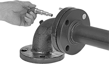
Magnetic Pipe Flange Aligners with Level
 | |
Ensure an even seal around your flange—these tools align and level flanges in a single step. The strong magnets make sure your bolt holes are perfectly inline horizontally and that your flange isn’t tilted. If your flange is made of stainless steel or another nonmagnetic material, secure these aligners using the included threaded cones.
For Flange Hole Dia. | For Max. Flange Hole Ctr.-to-Ctr. Distance | Level Lg. | Aligner Connection Method | Includes | Cone Material | Magnet Material | Container Type | Each | |||
|---|---|---|---|---|---|---|---|---|---|---|---|
Aluminum Body | |||||||||||
| 1/2" to 2" | 9 1/2" | 10 1/2" | Magnetic | Threaded Cones | Steel | Neodymium | Carrying Case | 7049N11 | 0000000 | ||
Pipe Flange Aligner Pins with Horizontal Level
Pipe Flange Aligner Pins
 |
Insert a pair of these nut-and-bolt pins into adjacent flange holes and tighten to align flanges before connecting two pipes. One pin in each pair has a level for vertical alignment. Use a separate level to align the flange horizontally. Also known as two-hole pins.
4 1/2" Lg. Extension—Pins with a 4 ½” length extension let you increase the length of your pins to align thicker flanges.
Two Couplings—Use the included couplings to connect the extension to your pins.

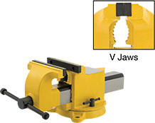
High-Visibility Bench Vises
With Flat and V-Jaws
 |
Vises | Replacement Flat Jaws | |||||||||||||||||||||
|---|---|---|---|---|---|---|---|---|---|---|---|---|---|---|---|---|---|---|---|---|---|---|
Flat Jaw | Overall | Mounting Holes | ||||||||||||||||||||
Wd. | Max. Opening | Material | Texture | V Jaw For Dia. | Throat Dp. | Lg. | Wd. | Ht. | Wt., lb. | Body Material | Mount Type | Mounting Fasteners Included | No. of | Dia. | Features | Specs. Met | Each | Each | ||||
360° Swivel Base | ||||||||||||||||||||||
| 4" | 4" | Steel | Serrated | 1/4" to 1 1/2" | 2 1/4" | 12 1/2" | 5 1/2" | 6" | 17 | Painted Steel | Bolt On | No | 3 | 1/2" | Anvil | OSHA Compliant 29 CFR 1910.144 | 5333A21 | 0000000 | 5333A24 | 000000 | ||
| 5" | 5" | Steel | Serrated | 1/2" to 1 1/2" | 2 5/8" | 14 1/2" | 6 1/2" | 6 3/4" | 24 | Painted Steel | Bolt On | No | 3 | 9/16" | Anvil | OSHA Compliant 29 CFR 1910.144 | 5333A22 | 000000 | 5333A25 | 00000 | ||
| 6" | 6" | Steel | Serrated | 1/2" to 2" | 3" | 17" | 6 3/4" | 7 1/2" | 33 | Painted Steel | Bolt On | No | 3 | 9/16" | Anvil | OSHA Compliant 29 CFR 1910.144 | 5333A23 | 000000 | 5333A26 | 00000 | ||
| 8" | 8" | Steel | Serrated | 3/4" to 2 1/4" | 3 1/2" | 19 1/2" | 8" | 8" | 49 | Painted Steel | Bolt On | No | 3 | 5/8" | Anvil | OSHA Compliant 29 CFR 1910.144 | 5333A38 | 000000 | ——— | 0 | ||
| 10" | 10" | Steel | Serrated | 7/8" to 2 3/4" | 4" | 22 1/2" | 10" | 8 1/2" | 56 | Painted Steel | Bolt On | No | 3 | 5/8" | Anvil | OSHA Compliant 29 CFR 1910.144 | 5333A41 | 000000 | ——— | 0 | ||
Pipe Flange Aligners with Protractor
 |
For Flange Hole Dia. | Angle Measured Range | Graduations (Angle Increments) | For Distance Between Bolt Holes | Each | |||
|---|---|---|---|---|---|---|---|
Aluminum | |||||||
| 3/16" to 1 3/4" | 0° to 90° | 2.5° (2°) | 2" to 5 1/2" | 2342A11 | 0000000 | ||
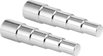
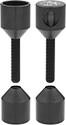
Magnetic Pipe Flange Aligner Pins
Swiftly and accurately align pipe flange bolt holes without the hassle of threads. These pins have strong magnets that snap together. Insert them into adjacent bolt holes to help make sure flanges are parallel before connecting pipes. Also known as two-hole pins.
For 2 3/4" Flange Thickness—Pins for 2 3/4" thick flanges can be used with pipe flange aligner extensions (sold separately) to lengthen their reach for flanges up to 3 1/2″ thick.
Pipe Flange Aligners | Pipe Flange Aligner Extensions | |||||||||
|---|---|---|---|---|---|---|---|---|---|---|
For Flange | ||||||||||
Hole Dia. | Thk. | Aligner Connection Method | Magnet Material | Pair | Lg. | Each | ||||
Steel | ||||||||||
| 5/16" to 7/8" | 7/8" | Magnetic | Neodymium | 7065N11 | 000000 | — | ——— | 0 | ||
| 1/2" to 1 7/16" | 1 3/8" | Magnetic | Neodymium | 7065N12 | 000000 | — | ——— | 0 | ||
| 3/4" to 1 15/16" | 2 3/4" | Magnetic | Neodymium | 7065N13 | 000000 | 1 3/4" | 7065N14 | 000000 | ||
