


How to Identify and Measure Fittings
Pipe size is an industry designation, not the actual size. View information about how to measure threaded and unthreaded pipe and pipe fittings.
More
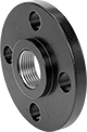
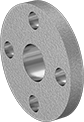
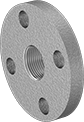
FM-Approved Low-Pressure Cast Iron Threaded Pipe Flanges
Suitable for use in fire-protection applications, these flanges are brittle and can be quickly opened with the strike of a sledge hammer. Bolt two flanges of the same size together with a gasket (sold separately) to create an access point within a line. Use in noncorrosive environments.
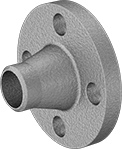
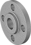
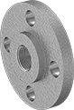
Reducing flanges transition your system to a smaller pipe size. Attach them to a flange with a larger pipe size but with the same flange dimensions.
- For Use With: Air, Natural Gas, Oil, Steam, Water
- Specifications Met:
3/4 Pipe Size: ASME B1.20.1, ASME B16.1, ASTM A126, FM Approved
All other sizes: ASME B1.20.1, ASME B16.1, ASTM A126, FM Approved, UL Listed - Pipe Nipples and Pipe: Use Schedule 40 steel
- Fittings: Use Class 125 iron and steel
Bolt Hole | ||||||||||
|---|---|---|---|---|---|---|---|---|---|---|
| Pipe Size | Flange OD | For Bolt Dia. | Dia. | No. of | Bolt Circle Dia. | Max. Pressure | Max. Steam Pressure | Material | Each | |
NPT | ||||||||||
| 3/4 | 3 7/8" | 1/2" | 5/8" | 4 | 2 3/4" | 125 psi @ 72° F | 125 psi @ 350° F | Iron | 000000000 | 000000 |
| 1 | 4 1/4" | 1/2" | 5/8" | 4 | 3 1/8" | 125 psi @ 72° F | 125 psi @ 350° F | Iron | 000000000 | 00000 |
| 1 1/4 | 4 5/8" | 1/2" | 5/8" | 4 | 3 1/2" | 125 psi @ 72° F | 125 psi @ 350° F | Iron | 000000000 | 00000 |
| 1 1/2 | 5" | 1/2" | 5/8" | 4 | 3 7/8" | 125 psi @ 72° F | 125 psi @ 350° F | Iron | 000000000 | 00000 |
| 2 | 6" | 5/8" | 3/4" | 4 | 4 3/4" | 125 psi @ 72° F | 125 psi @ 350° F | Iron | 000000000 | 00000 |
| 2 1/2 | 7" | 5/8" | 3/4" | 4 | 5 1/2" | 125 psi @ 72° F | 125 psi @ 350° F | Iron | 000000000 | 00000 |
| 3 | 7 1/2" | 5/8" | 3/4" | 4 | 6" | 125 psi @ 72° F | 125 psi @ 350° F | Iron | 000000000 | 00000 |
| 4 | 9" | 5/8" | 3/4" | 8 | 7 1/2" | 125 psi @ 72° F | 125 psi @ 350° F | Iron | 000000000 | 000000 |
| 5 | 10" | 3/4" | 7/8" | 8 | 8 1/2" | 125 psi @ 72° F | 125 psi @ 350° F | Iron | 000000000 | 000000 |
| 6 | 11" | 3/4" | 7/8" | 8 | 9 1/2" | 125 psi @ 72° F | 125 psi @ 350° F | Iron | 000000000 | 000000 |
| 8 | 13 1/2" | 3/4" | 7/8" | 8 | 11 3/4" | 125 psi @ 72° F | 125 psi @ 350° F | Iron | 000000000 | 000000 |

- For Use With: Air, Natural Gas, Oil, Steam, Water
- Specifications Met: ASME B1.20.1, ASME B16.1, ASTM A126, ASTM A153, FM Approved
- Pipe Nipples and Pipe: Use Schedule 40 iron and steel
- Fittings: Use Class 125 iron and steel
Bolt Hole | |||||||||||
|---|---|---|---|---|---|---|---|---|---|---|---|
| Pipe Size | For Flange Pipe Size | Flange OD | For Bolt Dia. | Dia. | No. of | Bolt Circle Dia. | Max. Pressure | Max. Steam Pressure | Material | Each | |
NPT | |||||||||||
| 2 | 2 1/2 | 7" | 5/8" | 3/4" | 4 | 5 1/2" | 175 psi @ 72° F | 125 psi @ 350° F | Iron | 000000000 | 000000 |
| 2 | 3 | 7 1/2" | 5/8" | 3/4" | 4 | 6" | 175 psi @ 72° F | 125 psi @ 350° F | Iron | 000000000 | 000000 |
| 2 | 4 | 9" | 5/8" | 3/4" | 8 | 7 1/2" | 175 psi @ 72° F | 125 psi @ 350° F | Iron | 000000000 | 000000 |
| 3 | 4 | 9" | 5/8" | 3/4" | 8 | 7 1/2" | 175 psi @ 72° F | 125 psi @ 350° F | Iron | 000000000 | 000000 |
| 4 | 6 | 11" | 3/4" | 7/8" | 8 | 9 1/2" | 175 psi @ 72° F | 125 psi @ 350° F | Iron | 000000000 | 000000 |
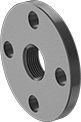
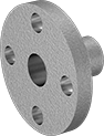
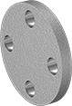
FM-Approved Low-Pressure Cast Iron Unthreaded Pipe Flanges


- For Use With: Air, Diesel Fuel, Gasoline, Natural Gas, Oil, Steam, Water
- Pressure Class: 125
- Specifications Met: ASME B1.20.1, ASME B16.1, ASTM A126, FM Approved
- Pipe Nipples and Pipe: Use Schedule 40 steel
- Fittings: Use Class 125 or 150 iron and steel
FM-approved for fire protection applications, these flanges are cast iron, so they're brittle and can be quickly opened by hitting them with a sledge hammer. Bolt them together with a gasket (not included) to create an access point within a low-pressure pipe line. All are cap flanges, which are also known as blind flanges. Use them in noncorrosive environments.
Bolt Hole | |||||||||
|---|---|---|---|---|---|---|---|---|---|
| Pipe Size | Flange OD | For Bolt Dia. | Dia. | No. of | Bolt Circle Dia. | Max. Pressure | Max. Steam Pressure | Each | |
| 1 | 4 1/4" | 1/2" | 5/8" | 4 | 3 1/8" | 200 psi @ 72° F | 165 psi @ 300° F | 0000000 | 000000 |
| 1 1/2 | 5" | 1/2" | 5/8" | 4 | 3 7/8" | 200 psi @ 72° F | 165 psi @ 300° F | 0000000 | 00000 |
| 2 | 6" | 5/8" | 3/4" | 4 | 4 3/4" | 200 psi @ 72° F | 165 psi @ 300° F | 0000000 | 00000 |
| 2 1/2 | 7" | 5/8" | 3/4" | 4 | 5 1/2" | 200 psi @ 72° F | 165 psi @ 300° F | 0000000 | 00000 |
| 3 | 7 1/2" | 5/8" | 3/4" | 4 | 6" | 200 psi @ 72° F | 165 psi @ 300° F | 0000000 | 00000 |
| 3 1/2 | 8 1/2" | 5/8" | 3/4" | 8 | 7" | 200 psi @ 72° F | 165 psi @ 300° F | 0000000 | 000000 |
| 4 | 9" | 5/8" | 3/4" | 8 | 7 1/2" | 200 psi @ 72° F | 165 psi @ 300° F | 0000000 | 000000 |
| 6 | 11" | 3/4" | 7/8" | 8 | 9 1/2" | 200 psi @ 72° F | 165 psi @ 300° F | 0000000 | 000000 |
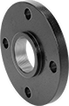
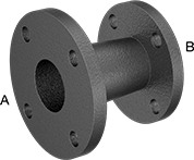
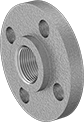
FM-Approved Iron Pipe Fittings with Flanged Ends
FM approved, these fittings are suitable for use in fire-protection systems. All have flat-surface flanged ends that only mate to another same-size flat-surface flange, pump, or valve with a gasket (sold separately) to create an access point in a pipeline. Use them in noncorrosive areas.
- For Use With: Air, Natural Gas, Oil, Steam, Water
- Specifications Met: FM Approved, UL Listed, ASTM A126, ASTM B307, Fed. Spec. WW-F-406, ASME B16.1, ASME B1.20.1
- Pipe Nipples and Pipe: Use Schedule 40 steel
- Flanges: Use Class 150 steel
Pipe Size | Flange OD | Bolt Hole | Bolt Circle Dia. | ||||||||||
|---|---|---|---|---|---|---|---|---|---|---|---|---|---|
| (A) | (B) | (A) | (B) | For Bolt Dia. | Dia. | No. of | (A) | (B) | Max. Pressure | Max. Steam Pressure | Material | Each | |
| 2 1/2 | 2 | 7" | 6" | 5/8" | 3/4" | 4 | 5 1/2" | 4 3/4" | 150 psi @ 72° F | 125 psi @ 350° F | Iron | 0000000 | 0000000 |
| 3 | 2 | 7 1/2" | 6" | 5/8" | 3/4" | 4 | 6" | 4 3/4" | 150 psi @ 72° F | 125 psi @ 350° F | Iron | 0000000 | 000000 |
| 3 | 2 1/2 | 7 1/2" | 7" | 5/8" | 3/4" | 4 | 6" | 5 1/2" | 150 psi @ 72° F | 125 psi @ 350° F | Iron | 0000000 | 000000 |
| 4 | 3 | 9" | 7 1/2" | 5/8" | 3/4" | 8 | 7 1/2" | 6" | 150 psi @ 72° F | 125 psi @ 350° F | Iron | 0000000 | 000000 |
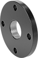
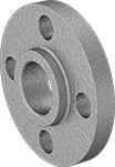
Aluminum Unthreaded Pipe Flanges
Also known as Pressure Class 125 flanges, these are for use in low-pressure applications. Bolt two same-size flanges together with a gasket (sold separately) to create an access point within a line. Flanges are aluminum, which is lightweight with good corrosion resistance.
Butt-weld flanges are also known as weld-neck flanges; the flange neck has a beveled end that, when flush to pipe, creates a trough for a strong weld. Slip-on weld flanges have no internal stop; slide a pipe through the flange and weld on both sides. Reducing flanges let you transition your system to a smaller pipe size; attach to a flange with a larger pipe size but with the same flange dimensions. Cap flanges are also known as blind flanges.
- For Use With: Air, Oil, Water
- Pressure Class: 125
- Specifications Met: ASME B16.1
- Fittings: Use Schedule 40 aluminum
- Pipe: Use Schedule 40 aluminum
Bolt Hole | ||||||||
|---|---|---|---|---|---|---|---|---|
| Pipe Size | Flange OD | For Bolt Dia. | Dia. | No. of | Bolt Circle Dia. | Max. Pressure | Each | |
| 1/2 | 3 1/2" | 1/2" | 5/8" | 4 | 2 3/8" | 150 psi @ 72° F | 000000000 | 000000 |
| 3/4 | 3 7/8" | 1/2" | 5/8" | 4 | 2 3/4" | 150 psi @ 72° F | 000000000 | 00000 |
| 1 | 4 1/4" | 1/2" | 5/8" | 4 | 3 1/8" | 150 psi @ 72° F | 000000000 | 00000 |
| 1 1/2 | 5" | 1/2" | 5/8" | 4 | 3 7/8" | 150 psi @ 72° F | 000000000 | 000000 |
| 2 | 6" | 5/8" | 3/4" | 4 | 4 3/4" | 150 psi @ 72° F | 000000000 | 000000 |
| 2 1/2 | 7" | 5/8" | 3/4" | 4 | 5 1/2" | 150 psi @ 72° F | 000000000 | 000000 |
| 3 | 7 1/2" | 5/8" | 3/4" | 4 | 6" | 150 psi @ 72° F | 000000000 | 000000 |
| 4 | 9" | 5/8" | 3/4" | 8 | 7 1/2" | 150 psi @ 72° F | 000000000 | 000000 |
| 6 | 11" | 3/4" | 7/8" | 8 | 9 1/2" | 150 psi @ 72° F | 000000000 | 000000 |
- For Use With: Air, Oil, Water
- Pressure Class: 125
- Specifications Met: ASME B16.1
- Fittings: Use Schedule 40 aluminum
- Pipe: Use Schedule 40 aluminum
Bolt Hole | ||||||||
|---|---|---|---|---|---|---|---|---|
| Pipe Size | Flange OD | For Bolt Dia. | Dia. | No. of | Bolt Circle Dia. | Max. Pressure | Each | |
| 1/2 | 3 1/2" | 1/2" | 5/8" | 4 | 2 3/8" | 150 psi @ 72° F | 00000000 | 000000 |
| 3/4 | 3 7/8" | 1/2" | 5/8" | 4 | 2 3/4" | 150 psi @ 72° F | 00000000 | 00000 |
| 1 | 4 1/4" | 1/2" | 5/8" | 4 | 3 1/8" | 150 psi @ 72° F | 000000000 | 00000 |
| 1 1/4 | 4 5/8" | 1/2" | 5/8" | 4 | 3 1/2" | 150 psi @ 72° F | 000000000 | 00000 |
| 1 1/2 | 5" | 1/2" | 5/8" | 4 | 3 7/8" | 150 psi @ 72° F | 000000000 | 00000 |
| 2 | 6" | 5/8" | 3/4" | 4 | 4 3/4" | 150 psi @ 72° F | 000000000 | 00000 |
| 2 1/2 | 7" | 5/8" | 3/4" | 4 | 5 1/2" | 150 psi @ 72° F | 000000000 | 00000 |
| 3 | 7 1/2" | 5/8" | 3/4" | 4 | 6" | 150 psi @ 72° F | 000000000 | 00000 |
| 4 | 9" | 5/8" | 3/4" | 8 | 7 1/2" | 150 psi @ 72° F | 000000000 | 000000 |
| 6 | 11" | 3/4" | 7/8" | 8 | 9 1/2" | 150 psi @ 72° F | 000000000 | 000000 |
| 8 | 13 1/2" | 3/4" | 7/8" | 8 | 11 3/4" | 150 psi @ 72° F | 000000000 | 000000 |

- For Use With: Air, Oil, Water
- Pressure Class: 125
- Specifications Met: ASME B16.1
- Fittings: Use Schedule 40 aluminum
- Pipe: Use Schedule 40 aluminum

- For Use With: Air, Oil, Water
- Pressure Class: 125
- Specifications Met: ASME B16.1
- Fittings: Use Schedule 40 aluminum
- Pipe: Use Schedule 40 aluminum
Bolt Hole | ||||||||
|---|---|---|---|---|---|---|---|---|
| Pipe Size | Flange OD | For Bolt Dia. | Dia. | No. of | Bolt Circle Dia. | Max. Pressure | Each | |
| 1/2 | 3 1/2" | 1/2" | 5/8" | 4 | 2 3/8" | 150 psi @ 72° F | 000000000 | 000000 |
| 3/4 | 3 7/8" | 1/2" | 5/8" | 4 | 2 3/4" | 150 psi @ 72° F | 000000000 | 00000 |
| 1 | 4 1/4" | 1/2" | 5/8" | 4 | 3 1/8" | 150 psi @ 72° F | 000000000 | 00000 |
| 1 1/4 | 4 5/8" | 1/2" | 5/8" | 4 | 3 1/2" | 150 psi @ 72° F | 000000000 | 00000 |
| 1 1/2 | 5" | 1/2" | 5/8" | 4 | 3 7/8" | 150 psi @ 72° F | 000000000 | 00000 |
| 2 | 6" | 5/8" | 3/4" | 4 | 4 3/4" | 150 psi @ 72° F | 000000000 | 00000 |
| 2 1/2 | 7" | 5/8" | 3/4" | 4 | 5 1/2" | 150 psi @ 72° F | 000000000 | 00000 |
| 3 | 7 1/2" | 5/8" | 3/4" | 4 | 6" | 150 psi @ 72° F | 000000000 | 000000 |
| 4 | 9" | 5/8" | 3/4" | 8 | 7 1/2" | 150 psi @ 72° F | 000000000 | 000000 |
| 6 | 11" | 3/4" | 7/8" | 8 | 9 1/2" | 150 psi @ 72° F | 000000000 | 000000 |
| 8 | 13 1/2" | 3/4" | 7/8" | 8 | 11 3/4" | 150 psi @ 72° F | 000000000 | 000000 |
Low-Pressure Aluminum Threaded Pipe Flanges
Also known as Pressure Class 125 flanges, these are for use in low-pressure applications. Bolt two same-size flanges together with a gasket (sold separately) to create an access point within a line. Flanges are aluminum, which is lightweight with good corrosion resistance.
Reducing flanges allow you to transition your system to a smaller pipe size; attach to a flange with a larger pipe size but with the same flange dimensions.
- For Use With: Air, Oil, Water
- Pressure Class: 125
- Specifications Met:
Pipe Size 1-6: ASME B16.1 - Fittings: Use Class 150 aluminum
- Pipe Nipples and Pipe: Use Schedule 40 aluminum
Bolt Hole | ||||||||
|---|---|---|---|---|---|---|---|---|
| Pipe Size | Flange OD | For Bolt Dia. | Dia. | No. of | Bolt Circle Dia. | Max. Pressure | Each | |
NPT | ||||||||
| 1 | 4 1/4" | 1/2" | 5/8" | 4 | 3 1/8" | 150 psi @ 72° F | 000000000 | 000000 |
| 1 1/4 | 4 5/8" | 1/2" | 5/8" | 4 | 3 1/2" | 150 psi @ 72° F | 000000000 | 00000 |
| 1 1/2 | 5" | 1/2" | 5/8" | 4 | 3 7/8" | 150 psi @ 72° F | 000000000 | 00000 |
| 2 | 6" | 5/8" | 3/4" | 4 | 4 3/4" | 150 psi @ 72° F | 000000000 | 00000 |
| 2 1/2 | 7" | 5/8" | 3/4" | 4 | 5 1/2" | 150 psi @ 72° F | 000000000 | 00000 |
| 3 | 7 1/2" | 5/8" | 3/4" | 4 | 6" | 150 psi @ 72° F | 000000000 | 00000 |
| 4 | 9" | 5/8" | 3/4" | 8 | 7 1/2" | 150 psi @ 72° F | 000000000 | 000000 |
| 6 | 11" | 3/4" | 7/8" | 8 | 9 1/2" | 150 psi @ 72° F | 000000000 | 000000 |
| 8 | 13 1/2" | 3/4" | 7/8" | 8 | 11 3/4" | 150 psi @ 72° F | 000000000 | 000000 |

- For Use With: Air, Oil, Water
- Pressure Class: 125
- Specifications Met: ASME B16.1
- Fittings: Use Class 150 aluminum
- Pipe Nipples and Pipe: Use Schedule 40 aluminum
Bolt Hole | |||||||||
|---|---|---|---|---|---|---|---|---|---|
| Pipe Size | For Flange Pipe Size | Flange OD | For Bolt Dia. | Dia. | No. of | Bolt Circle Dia. | Max. Pressure | Each | |
NPT | |||||||||
| 1/2 | 3/4 | 3 7/8" | 1/2" | 5/8" | 4 | 2 3/4" | 150 psi @ 72° F | 000000000 | 000000 |
| 3/4 | 1 | 4 1/4" | 1/2" | 5/8" | 4 | 3 1/8" | 150 psi @ 72° F | 000000000 | 00000 |
| 1 | 1 1/4 | 4 5/8" | 1/2" | 5/8" | 4 | 3 1/2" | 150 psi @ 72° F | 000000000 | 00000 |
| 1 1/4 | 1 1/2 | 5" | 1/2" | 5/8" | 4 | 3 7/8" | 150 psi @ 72° F | 000000000 | 00000 |
| 1 1/2 | 2 | 6" | 5/8" | 3/4" | 4 | 4 3/4" | 150 psi @ 72° F | 000000000 | 00000 |
| 2 | 2 1/2 | 7" | 5/8" | 3/4" | 4 | 5 1/2" | 150 psi @ 72° F | 000000000 | 00000 |
| 2 | 3 | 7 1/2" | 5/8" | 3/4" | 4 | 6" | 150 psi @ 72° F | 000000000 | 000000 |
| 3 | 4 | 9" | 5/8" | 3/4" | 8 | 7 1/2" | 150 psi @ 72° F | 000000000 | 000000 |
| 4 | 6 | 11" | 3/4" | 7/8" | 8 | 9 1/2" | 150 psi @ 72° F | 000000000 | 000000 |
| 6 | 8 | 13 1/2" | 3/4" | 7/8" | 8 | 11 3/4" | 150 psi @ 72° F | 000000000 | 000000 |