


How to Identify and Measure Fittings
Pipe size is an industry designation, not the actual size. View information about how to measure threaded and unthreaded pipe and pipe fittings.
More
Low-Pressure Brass and Bronze Threaded Pipe Fittings
Use these fittings in low-pressure flow applications. They have good corrosion resistance. Fittings rated for use with drinking water meet NSF/ANSI 61 safety standards.
![]() For technical drawings and 3-D models, click on a part number.
For technical drawings and 3-D models, click on a part number.
- For Use With:
Brass: Air, Drinking Water, Natural Gas, Oil
Bronze: Air, Natural Gas, Oil, Steam, Water - Pressure Class: 125
- Specifications Met: See table
- Pipe Nipples and Pipe: Use Schedule 40 brass
- Flanges: See table
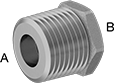
Low-Pressure Iron and Steel Threaded Pipe Fittings
Use these fittings for low-pressure applications in noncorrosive environments.
![]() For technical drawings and 3-D models, click on a part number.
For technical drawings and 3-D models, click on a part number.
- For Use With: Air, Steam, Oil, Water, Natural Gas
- Pressure Class: See table
- Pipe Nipples and Pipe: Use Schedule 40 steel
- Specifications Met: See table
Pipe Size | ||||||||
|---|---|---|---|---|---|---|---|---|
| (A) | (B) | Pressure Class | Max. Pressure | Max. Steam Pressure | Material | Specifications Met | Each | |
NPT Male × NPT Female | ||||||||
| 3 1/2 | 1 | 125 | 175 psi @ 72° F | 125 psi @ 350° F | Iron | ASME B16.14 | 000000000 | 000000 |
| 3 1/2 | 1 1/4 | 125 | 175 psi @ 72° F | 125 psi @ 350° F | Iron | ASME B16.14 | 000000000 | 00000 |
| 3 1/2 | 1 1/2 | 125 | 175 psi @ 72° F | 125 psi @ 350° F | Iron | ASME B16.14 | 000000000 | 00000 |
| 3 1/2 | 2 | 125 | 175 psi @ 72° F | 125 psi @ 350° F | Iron | ASME B16.14 | 000000000 | 00000 |
| 3 1/2 | 2 1/2 | 125 | 175 psi @ 72° F | 125 psi @ 350° F | Iron | ASME B16.14 | 000000000 | 00000 |
| 3 1/2 | 3 | 125 | 175 psi @ 72° F | 125 psi @ 350° F | Iron | ASME B16.14 | 000000000 | 00000 |
| 4 | 3 1/2 | 150 | 150 psi @ 72° F | 150 psi @ 350° F | Iron | ASME B16.14 | 000000000 | 00000 |
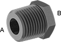
- For Use With: Air, Steam, Oil, Water, Natural Gas
- Specifications Met:
NPT: ASME B1.20.1, ASME B16.3, UL Listed
BSPT: DIN EN 10226 - Pipe Nipples and Pipe: Use Schedule 40 steel
- For Use With: Air, Steam, Oil, Water, Natural Gas
- Presure Class:
Steel: 150
Iron: 125 - Pipe Nipples and Pipe: Use Schedule 40 steel
| Pipe Size | Plug Construction | Max. Pressure | Max. Steam Pressure | Material | Each | |
NPT Male | ||||||
|---|---|---|---|---|---|---|
| 3 1/2 | Hollow | 175 psi @ 72° F | 125 psi @ 350° F | Iron | 000000000 | 000000 |
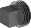
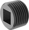
- For Use With:
NPT and BSPT: Air, Natural Gas, Oil, Steam, Water
NPTF: Air, Natural Gas, Steam, Water - Pressure Class:
NPT Iron: 125
BSPT Iron: 150 - Specifications Met:
See table - Pipe Nipples and Pipe:
NPT and BPST: Use Schedule 40 steel
| Pipe Size | Plug Construction | Max. Pressure | Max. Steam Pressure | Material | Each | |
NPT Male | ||||||
|---|---|---|---|---|---|---|
| 3 1/2 | Hollow | 175 psi @ 72° F | 125 psi @ 350° F | Iron | 000000000 | 000000 |
Low-Pressure Steel Threaded Pipe Flanges
Use these flanges for low-pressure applications in noncorrosive environments. Bolt two flanges of the same size together with a gasket (sold separately) to create an access point within a line.
![]() For technical drawings and 3-D models, click on a part number.
For technical drawings and 3-D models, click on a part number.


- For Use With: Air, Natural Gas, Oil, Steam, Water
- Pressure Class: 150
- Specifications Met:
NPT: ASME B16.5, ASTM A105, MSS SP-25
BSPT: ASTM A105 - Fittings: Use Class 125 or 150 iron and steel
- Pipe Nipples and Pipe: Use Schedule 40 steel
Bolt Hole | ||||||||||
|---|---|---|---|---|---|---|---|---|---|---|
| Pipe Size | Flange OD | For Bolt Dia. | Dia. | No. of | Bolt Circle Dia. | Max. Pressure | Max. Steam Pressure | Material | Each | |
NPT | ||||||||||
| 3 1/2 | 8 1/2" | 5/8" | 3/4" | 8 | 7" | 285 psi @ 72° F | 230 psi @ 300° F | Steel | 000000000 | 0000000 |
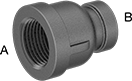
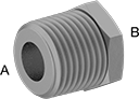
Low-Pressure Galvanized Iron and Steel Threaded Pipe Fittings
The galvanized finish on these fittings provides fair corrosion resistance. Fittings are for use in low-pressure applications.
![]() For technical drawings and 3-D models, click on a part number.
For technical drawings and 3-D models, click on a part number.
- For Use With: Air, Steam, Oil, Water, Natural Gas
- Pressure Class: See table
- Specifications Met: See table
- Pipe Nipples and Pipe: Use Schedule 40 galvanized steel
- Flanges: Use Class 150 galvanized steel
Pipe Size | ||||||||
|---|---|---|---|---|---|---|---|---|
| (A) | (B) | Pressure Class | Max. Pressure | Max. Steam Pressure | Material | Specifications Met | Each | |
NPT Male × NPT Female | ||||||||
| 4 | 3 1/2 | 150 | 150 psi @ 72° F | 150 psi @ 350° F | Galvanized Iron | ASME B16.14 | 00000000 | 0000000 |
| 3 1/2 | 1 | 125 | 125 psi @ 72° F | 125 psi @ 350° F | Galvanized Iron | ASME B1.20.1, ASME B16.14, ASTM A126, UL Listed | 00000000 | 00000 |
| 3 1/2 | 1 1/4 | 125 | 125 psi @ 72° F | 125 psi @ 350° F | Galvanized Iron | ASME B1.20.1, ASME B16.14, ASTM A126, UL Listed | 00000000 | 00000 |
| 3 1/2 | 1 1/2 | 125 | 125 psi @ 72° F | 125 psi @ 350° F | Galvanized Iron | ASME B1.20.1, ASME B16.14, ASTM A126, UL Listed | 00000000 | 000000 |
| 3 1/2 | 2 | 125 | 125 psi @ 72° F | 125 psi @ 350° F | Galvanized Iron | ASME B1.20.1, ASME B16.14, ASTM A126, UL Listed | 00000000 | 000000 |
| 3 1/2 | 3 | 125 | 125 psi @ 72° F | 125 psi @ 350° F | Galvanized Iron | ASME B1.20.1, ASME B16.14, ASTM A126, UL Listed | 00000000 | 000000 |
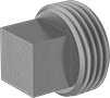
- For Use With: Air, Steam, Oil, Water, Natural Gas
- Pressure Class: See table
- Specifications Met:
NPT Steel: SAE J531
NPT Iron: ASME B1.20.1, ASME B16.14, ASTM A126, UL Listed
BSPT: ASTM A197, DIN EN 10226 - Pipe Nipples and Pipe: Use Schedule 40 steel
- Flanges: Use Class 150 galvanized steel
| Pipe Size | Plug Construction | Pressure Class | Max. Pressure | Max. Steam Pressure | Material | Each | |
NPT Male | |||||||
|---|---|---|---|---|---|---|---|
| 3 1/2 | Hollow | 125 | 125 psi @ 72° F | 125 psi @ 350° F | Galvanized Iron | 00000000 | 0000000 |
FM-Approved Low-Pressure Cast Iron Unthreaded Pipe Flanges


- For Use With: Air, Diesel Fuel, Gasoline, Natural Gas, Oil, Steam, Water
- Pressure Class: 125
- Specifications Met: ASME B1.20.1, ASME B16.1, ASTM A126, FM Approved
- Pipe Nipples and Pipe: Use Schedule 40 steel
- Fittings: Use Class 125 or 150 iron and steel
FM-approved for fire protection applications, these flanges are cast iron, so they're brittle and can be quickly opened by hitting them with a sledge hammer. Bolt them together with a gasket (not included) to create an access point within a low-pressure pipe line. All are cap flanges, which are also known as blind flanges. Use them in noncorrosive environments.
![]() For technical drawings and 3-D models, click on a part number.
For technical drawings and 3-D models, click on a part number.
Bolt Hole | |||||||||
|---|---|---|---|---|---|---|---|---|---|
| Pipe Size | Flange OD | For Bolt Dia. | Dia. | No. of | Bolt Circle Dia. | Max. Pressure | Max. Steam Pressure | Each | |
| 3 1/2 | 8 1/2" | 5/8" | 3/4" | 8 | 7" | 200 psi @ 72° F | 165 psi @ 300° F | 0000000 | 0000000 |
Standard-Wall Plastic Pipe for Water
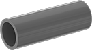
Connect this pipe to standard-wall plastic pipe fittings for a variety of residential and commercial low-pressure plumbing and water supply applications. It’s made of PVC, which has good corrosion resistance. Pipe meets NSF/ANSI Standard 61 for drinking water. It also meets ASTM D1784 and ASTM D1785 specifications and testing requirements for material quality. Connect this pipe to unthreaded female socket-connect fittings using a PVC primer and cement (also known as solvent weld).
Warning: Never use plastic pipe fittings and pipe with compressed air or gas.
![]() For technical drawings and 3-D models, click on a part number.
For technical drawings and 3-D models, click on a part number.
- For Use With: Drinking Water, Water
- Maximum Temperature: 140° F
- Specifications Met: ASTM D1784, ASTM D1785, NSF/ANSI 61
- Fittings: Use Schedule 40 PVC Plastic
- Flanges: Use Schedule 40 PVC Plastic
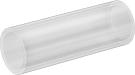
Clear-View Standard-Wall Plastic Pipe for Water
See inside your line with this clear pipe, which works in a variety of residential and commercial low-pressure plumbing and water supply applications. It connects to standard-wall plastic pipe fittings. Made of PVC, it has good corrosion resistance. Join this pipe to unthreaded female socket-connect fittings using a PVC primer and cement (also known as solvent weld).
Warning: Never use plastic pipe fittings and pipe with compressed air or gas.
![]() For technical drawings and 3-D models, click on a part number.
For technical drawings and 3-D models, click on a part number.
- For Use With: Drinking Water, Water
- Maximum Temperature: 140° F
- Specifications Met: ASTM D1784, ASTM D1785, NSF/ANSI 61
- Fittings: Use Schedule 40 PVC Plastic
- Flanges: Use Schedule 40 PVC Plastic
Rigid pipe meets NSF/ANSI 61 for use with drinking water systems. It also meets ASTM D1784 and ASTM D1785 specifications and testing requirements for material quality.
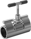
Low-Pressure Quick-Lock Clamp-On Connectors for Air
- For Use With: Air
- Temperature Range: -30° to 180° F
- For Pipe Material: Stainless Steel, Iron, Steel, Aluminum, Copper, PVC Plastic, CPVC Plastic
A turn of the T-handle will tighten and loosen these connectors, so you can quickly disassemble and reassemble your lines without tools. Use connectors to join pieces of rigid pipe of the same or different materials. They are commonly used in gravity-flow systems and low-pressure air and vacuum conveying systems. Connectors have a metal strip that provides an escape route for electrostatic buildup when used in a fully grounded system.
![]() For technical drawings and 3-D models, click on a part number.
For technical drawings and 3-D models, click on a part number.
| For Pipe OD | For Pipe Size | Lg. | Max. Pressure | Max. Vacuum | Material | Gasket Material | Each | |
| 4" | 3 1/2 | 4" | 15 psi @ 72° F | 15 in. of Hg @ 72° F | 304 Stainless Steel | Gum Rubber | 0000000 | 000000 |
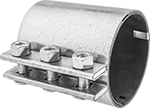
Low-Pressure Clamp-On Connectors for Air
- For Use With: Air
- Temperature Range:
Neoprene Rubber Gasket: -20° to 190° F
Silicone Rubber Gasket: -100° to 500° F - For Pipe Material: Stainless Steel, Iron, Steel, Aluminum, Copper, PVC Plastic, CPVC Plastic
Tighten the bolts on these connectors to join two pieces of rigid pipe of the same or different materials. They are for use in low-pressure air and vacuum conveying systems, as well as in gravity-flow systems. Connectors have a stainless steel strip that provides an escape route for electrostatic buildup when used in a fully grounded system.
Connectors with sleeve have an inner lining that protects the gasket.
![]() For technical drawings and 3-D models, click on a part number.
For technical drawings and 3-D models, click on a part number.
| For Pipe OD | For Pipe Size | Lg. | No. of Bolts | Max. Pressure | Max. Vacuum | Material | Nut Material | Bolt Material | Each | |
Neoprene Rubber Gasket | ||||||||||
|---|---|---|---|---|---|---|---|---|---|---|
Connectors with 430 Stainless Steel Sleeve | ||||||||||
| 4" | 3 1/2 | 8" | 4 | 15 psi @ 72° F | 15 in. of Hg @ 72° F | Galvanized Steel | Zinc-Plated Steel | Zinc-Plated Steel | 0000000 | 000000 |
Silicone Rubber Gasket | ||||||||||
Connectors with 430 Stainless Steel Sleeve | ||||||||||
| 4" | 3 1/2 | 8" | 4 | 15 psi @ 72° F | 15 in. of Hg @ 72° F | Galvanized Steel | Zinc-Plated Steel | Zinc-Plated Steel | 0000000 | 00000 |
Cleanout Plugs
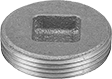
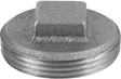
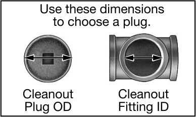
Close off your drain cleanout pipe with these threaded plugs. Note: If you do not know your pipe size, measure the OD of your existing cleanout plug or the ID of your cleanout fitting and match to the value listed.