Filter by
Body Material
Fitting Connection


Actuation
For Use With
Disc Material
Maximum Pressure @ Temperature
Maximum Temperature
Ball Material
DFARS Specialty Metals
Seal Material
Body Finish
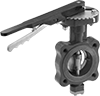
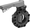
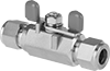
Flow-Adjustment Valves
Flow-Adjustment Valves
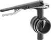
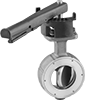
Flanged Flow-Adjustment Valves