


Filter by
System of Measurement
Cable OD
Wire Connection Method
Electrical Connection

Material
Wire Connection
Shielding
Mounting Location
Maximum Temperature


Impedance @ Frequency
REACH
DFARS Specialty Metals
Export Control Classification Number (ECCN)
Filtered D-Sub Connectors
Plugs |
Sockets |
DB9 |
DB15 |
DB25 |
DB37 |
With a ferrite filter block surrounding their contacts, these connectors control and reduce the electromagnetic (EMI) and radio frequency (RFI) interference traveling through them. They have solder cup terminals that hold wire leads in place when you’re soldering them, helping you create a stable connection.
Mounting Holes | DB9 Connection | DB15 Connection | DB25 Connection | DB37 Connection | |||||||||||
|---|---|---|---|---|---|---|---|---|---|---|---|---|---|---|---|
For Wire Ga. | Interference Reduction @ Freq. | Housing Material | No. of | Dia., mm | Flammability Rating | Each | Each | Each | Each | ||||||
Solder Wire Inlet Connection | |||||||||||||||
Shielded Plugs | |||||||||||||||
| 20 | 4 dB @ 1 GHz | Nickel-Plated Steel | 2 | 3 | UL 94 V-0 | 8609N11 | 00000 | 8609N12 | 00000 | 8609N13 | 00000 | 8609N14 | 000000 | ||
Shielded Sockets | |||||||||||||||
| 20 | 4 dB @ 1 GHz | Nickel-Plated Steel | 2 | 3 | UL 94 V-0 | 8609N15 | 0000 | 8609N16 | 0000 | 8609N17 | 0000 | ——— | 0 | ||
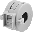
EMI/RFI Suppressing Clips
 | 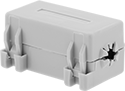 | 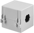 |
Style A | Style B | Style C |
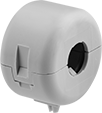 | 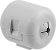 |  |
Style D | Style E | Style F |
Style | For Cable OD | Mount Type | Impedance @ Freq. | Freq. Range, MHz | Shield Material | Lg. | Wd. | Ht. | Housing Material | Color | Each | |||
|---|---|---|---|---|---|---|---|---|---|---|---|---|---|---|
Rigid | ||||||||||||||
| A | 0.3" | Screw | 100 ohm @ 100 MHz | 10 to 1 | Ferrite Ceramic | 7/8" | 13/16" | 7/8" | Nylon | Gray | 70055K71 | 000000 | ||
| A | 0.3" | Adhesive | 100 ohm @ 100 MHz | 10 to 1 | Ferrite Ceramic | 7/8" | 13/16" | 7/8" | Nylon | Gray | 70055K128 | 00000 | ||
| A | 0.34" | Screw | 22 ohm @ 30 MHz | 1 to 60 | Ferrite Ceramic | 11/16" | 1" | 1" | Nylon | Gray | 70055K122 | 00000 | ||
| A | 0.34" | Screw | 73 ohm @ 100 MHz | 10 to 1 | Ferrite Ceramic | 11/16" | 1" | 1" | Nylon | Gray | 70055K12 | 00000 | ||
| A | 0.42" | Screw | 117 ohm @ 100 MHz | 10 to 1 | Ferrite Ceramic | 3/4" | 1 1/8" | 1 3/16" | Nylon | Gray | 70055K13 | 00000 | ||
| A | 0.42" | Screw | 305 ohm @ 700 MHz | 1 to 1 | Ferrite Ceramic | 3/4" | 1 1/8" | 1 3/16" | Nylon | Gray | 70055K123 | 00000 | ||
| A | 0.52" | Screw | 62 ohm @ 100 MHz | 10 to 1 | Ferrite Ceramic | 11/16" | 1 1/4" | 1 3/16" | Nylon | Gray | 70055K72 | 00000 | ||
| A | 0.71" | Screw | 177 ohm @ 100 MHz | 10 to 1 | Ferrite Ceramic | 1 1/4" | 1 11/16" | 1 11/16" | Nylon | Gray | 70055K11 | 00000 | ||
| A | 0.96" | Screw | 210 ohm @ 30 MHz | 1 to 60 | Ferrite Ceramic | 1 13/16" | 2 5/16" | 2 3/8" | Nylon | Gray | 70055K124 | 00000 | ||
| A | 0.96" | Screw | 380 ohm @ 100 MHz | 10 to 1 | Ferrite Ceramic | 1 13/16" | 2 5/16" | 2 3/8" | Nylon | Gray | 70055K125 | 00000 | ||
| A | 0.96" | Adhesive | 380 ohm @ 100 MHz | 10 to 1 | Ferrite Ceramic | 1 13/16" | 2 5/16" | 2 3/8" | Nylon | Gray | 70055K129 | 00000 | ||
| A | 1.96" | Screw | 140 ohm @ 30 MHz | 1 to 60 | Ferrite Ceramic | 1 13/16" | 4 11/16" | 4 1/2" | Nylon | Gray | 70055K126 | 000000 | ||
| A | 1.96" | Screw | 290 ohm @ 100 MHz | 10 to 1 | Ferrite Ceramic | 1 13/16" | 4 11/16" | 4 1/2" | Nylon | Gray | 70055K127 | 000000 | ||
| B | 0.2" | — | 200 ohm @ 100 MHz | 10 to 1 | Ferrite Ceramic | 1 1/4" | 13/16" | 11/16" | Nylon | Gray | 70055K75 | 00000 | ||
| B | 0.3" | — | 200 ohm @ 100 MHz | 10 to 1 | Ferrite Ceramic | 1 1/4" | 7/8" | 13/16" | Nylon | Gray | 70055K76 | 00000 | ||
| C | 0.08" | — | 105 ohm @ 100 MHz | 10 to 1 | Ferrite Ceramic | 1/2" | 7/16" | 7/16" | Nylon | Gray | 70055K81 | 00000 | ||
| C | 0.08" | Adhesive | 105 ohm @ 100 MHz | 10 to 1 | Ferrite Ceramic | 1/2" | 7/16" | 7/16" | Nylon | Gray | 70055K89 | 00000 | ||
| C | 0.2" | Adhesive | 200 ohm @ 100 MHz | 10 to 1 | Ferrite Ceramic | 1 1/4" | 13/16" | 11/16" | Nylon | Gray | 70055K91 | 00000 | ||
| C | 0.24" | — | 23 ohm @ 30 MHz | 1 to 60 | Ferrite Ceramic | 1 1/4" | 7/8" | 13/16" | Nylon | Gray | 70055K82 | 00000 | ||
| C | 0.24" | — | 390 ohm @ 700 MHz | 1 to 1 | Ferrite Ceramic | 1 1/4" | 7/8" | 13/16" | Nylon | Gray | 70055K83 | 00000 | ||
| C | 0.24" | Adhesive | 23 ohm @ 30 MHz | 1 to 60 | Ferrite Ceramic | 1 1/4" | 7/8" | 13/16" | Nylon | Gray | 70055K92 | 00000 | ||
| C | 0.24" | Adhesive | 390 ohm @ 700 MHz | 1 to 1 | Ferrite Ceramic | 1 1/4" | 7/8" | 13/16" | Nylon | Gray | 70055K93 | 00000 | ||
| C | 0.27" | — | 200 ohm @ 100 MHz | 10 to 1 | Ferrite Ceramic | 1 1/4" | 7/8" | 13/16" | Nylon | Gray | 70055K14 | 00000 | ||
| C | 0.27" | Adhesive | 200 ohm @ 100 MHz | 10 to 1 | Ferrite Ceramic | 1 1/4" | 7/8" | 13/16" | Nylon | Gray | 70055K94 | 00000 | ||
| C | 0.3" | — | 23 ohm @ 30 MHz | 1 to 60 | Ferrite Ceramic | 1 1/4" | 7/8" | 13/16" | Nylon | Gray | 70055K84 | 00000 | ||
| C | 0.3" | — | 390 ohm @ 700 MHz | 1 to 1 | Ferrite Ceramic | 1 1/4" | 7/8" | 13/16" | Nylon | Gray | 70055K85 | 00000 | ||
| C | 0.3" | Adhesive | 23 ohm @ 30 MHz | 1 to 60 | Ferrite Ceramic | 1 1/4" | 7/8" | 13/16" | Nylon | Gray | 70055K95 | 00000 | ||
| C | 0.3" | Adhesive | 200 ohm @ 100 MHz | 10 to 1 | Ferrite Ceramic | 1 1/4" | 7/8" | 13/16" | Nylon | Gray | 70055K96 | 00000 | ||
| C | 0.3" | Adhesive | 390 ohm @ 700 MHz | 1 to 1 | Ferrite Ceramic | 1 1/4" | 7/8" | 13/16" | Nylon | Gray | 70055K97 | 00000 | ||
| C | 0.38" | — | 27 ohm @ 30 MHz | 1 to 60 | Ferrite Ceramic | 1 1/4" | 1 1/4" | 1 3/16" | Nylon | Gray | 70055K86 | 00000 | ||
| C | 0.38" | — | 230 ohm @ 100 MHz | 10 to 1 | Ferrite Ceramic | 1 1/4" | 1 1/4" | 1 3/16" | Nylon | Gray | 70055K87 | 00000 | ||
| C | 0.38" | Adhesive | 27 ohm @ 30 MHz | 1 to 60 | Ferrite Ceramic | 1 1/4" | 1 1/4" | 1 3/16" | Nylon | Gray | 70055K98 | 00000 | ||
| C | 0.38" | Adhesive | 230 ohm @ 100 MHz | 10 to 1 | Ferrite Ceramic | 1 1/4" | 1 1/4" | 1 3/16" | Nylon | Gray | 70055K99 | 00000 | ||
| C | 0.45" | — | 238 ohm @ 100 MHz | 10 to 1 | Ferrite Ceramic | 1 1/4" | 1 1/16" | 1" | Nylon | Gray | 70055K16 | 00000 | ||
| C | 0.45" | Adhesive | 238 ohm @ 100 MHz | 10 to 1 | Ferrite Ceramic | 1 1/4" | 1 1/16" | 1" | Nylon | Gray | 70055K101 | 00000 | ||
| C | 0.5" | — | 27 ohm @ 30 MHz | 1 to 60 | Ferrite Ceramic | 1 1/4" | 1 1/4" | 1 3/16" | Nylon | Gray | 70055K88 | 00000 | ||
| C | 0.5" | Adhesive | 27 ohm @ 30 MHz | 1 to 60 | Ferrite Ceramic | 1 1/4" | 1 1/4" | 1 3/16" | Nylon | Gray | 70055K102 | 00000 | ||
| C | 0.55" | — | 230 ohm @ 100 MHz | 10 to 1 | Ferrite Ceramic | 1 1/4" | 1 1/4" | 1 3/16" | Nylon | Gray | 70055K15 | 00000 | ||
| C | 0.55" | Adhesive | 230 ohm @ 100 MHz | 10 to 1 | Ferrite Ceramic | 1 1/4" | 1 1/4" | 1 3/16" | Nylon | Gray | 70055K103 | 00000 | ||
| D | 0.3" | Press Fit | 100 ohm @ 100 MHz | 10 to 1 | Ferrite Ceramic | 7/8" | 13/16" | 7/8" | Nylon | Gray | 70055K134 | 00000 | ||
| D | 0.42" | Press Fit | 117 ohm @ 100 MHz | 10 to 1 | Ferrite Ceramic | 3/4" | 1 1/8" | 1 3/16" | Nylon | Gray | 70055K135 | 00000 | ||
| F | 0.3" | Cable Tie | 100 ohm @ 100 MHz | 10 to 1 | Ferrite Ceramic | 11/16" | 13/16" | 7/8" | Nylon | Gray | 70055K131 | 00000 | ||
| F | 0.34" | Cable Tie | 73 ohm @ 100 MHz | 10 to 1 | Ferrite Ceramic | 1/2" | 1" | 1 3/16" | Nylon | Gray | 70055K132 | 00000 | ||
| F | 0.42" | Cable Tie | 117 ohm @ 100 MHz | 10 to 1 | Ferrite Ceramic | 11/16" | 1 1/16" | 1 3/16" | Nylon | Gray | 70055K133 | 00000 | ||
Flexible | ||||||||||||||
| B | 0.13"-0.17" | — | 220 ohm @ 100 MHz | 10 to 1 | Ferrite Ceramic | 1 1/4" | 11/16" | 9/16" | Nylon | Gray | 70055K77 | 00000 | ||
| B | 0.13"-0.17" | Adhesive | 220 ohm @ 100 MHz | 10 to 1 | Ferrite Ceramic | 1 1/4" | 11/16" | 9/16" | Nylon | Gray | 70055K112 | 00000 | ||
| B | 0.21"-0.3" | — | 23 ohm @ 30 MHz | 1 to 60 | Ferrite Ceramic | 1 7/16" | 7/8" | 13/16" | Nylon | Gray | 70055K105 | 00000 | ||
| B | 0.21"-0.3" | — | 200 ohm @ 100 MHz | 10 to 1 | Ferrite Ceramic | 1 7/16" | 7/8" | 13/16" | Nylon | Gray | 70055K108 | 00000 | ||
| B | 0.21"-0.3" | — | 390 ohm @ 700 MHz | 1 to 1 | Ferrite Ceramic | 1 7/16" | 7/8" | 13/16" | Nylon | Gray | 70055K109 | 00000 | ||
| B | 0.21"-0.3" | Adhesive | 23 ohm @ 30 MHz | 1 to 60 | Ferrite Ceramic | 1 7/16" | 7/8" | 13/16" | Nylon | Gray | 70055K115 | 00000 | ||
| B | 0.21"-0.3" | Adhesive | 200 ohm @ 100 MHz | 10 to 1 | Ferrite Ceramic | 1 7/16" | 7/8" | 13/16" | Nylon | Gray | 70055K118 | 00000 | ||
| B | 0.21"-0.3" | Adhesive | 390 ohm @ 700 MHz | 1 to 1 | Ferrite Ceramic | 1 7/16" | 7/8" | 13/16" | Nylon | Gray | 70055K119 | 00000 | ||
| B | 0.25"-0.4" | — | 238 ohm @ 100 MHz | 10 to 1 | Ferrite Ceramic | 1 7/16" | 1 1/16" | 1" | Nylon | Gray | 70055K107 | 00000 | ||
| B | 0.25"-0.4" | Adhesive | 238 ohm @ 100 MHz | 10 to 1 | Ferrite Ceramic | 1 7/16" | 1 1/16" | 1" | Nylon | Gray | 70055K117 | 00000 | ||
| B | 0.25"-0.5" | — | 27 ohm @ 30 MHz | 1 to 60 | Ferrite Ceramic | 1 7/16" | 1 1/4" | 1 3/16" | Nylon | Gray | 70055K106 | 00000 | ||
| B | 0.25"-0.5" | — | 230 ohm @ 100 MHz | 10 to 1 | Ferrite Ceramic | 1 7/16" | 1 1/4" | 1 3/16" | Nylon | Gray | 70055K78 | 00000 | ||
| B | 0.25"-0.5" | — | 510 ohm @ 700 MHz | 1 to 1 | Ferrite Ceramic | 1 7/16" | 1 1/4" | 1 3/16" | Nylon | Gray | 70055K111 | 00000 | ||
| B | 0.25"-0.5" | Adhesive | 27 ohm @ 30 MHz | 1 to 60 | Ferrite Ceramic | 1 7/16" | 1 1/4" | 1 3/16" | Nylon | Gray | 70055K116 | 00000 | ||
| B | 0.25"-0.5" | Adhesive | 230 ohm @ 100 MHz | 10 to 1 | Ferrite Ceramic | 1 7/16" | 1 1/4" | 1 3/16" | Nylon | Gray | 70055K113 | 00000 | ||
| B | 0.25"-0.5" | Adhesive | 510 ohm @ 700 MHz | 1 to 1 | Ferrite Ceramic | 1 7/16" | 1 1/4" | 1 3/16" | Nylon | Gray | 70055K121 | 00000 | ||
| B | 0.5"-0.71" | — | 260 ohm @ 100 MHz | 10 to 1 | Ferrite Ceramic | 1 13/16" | 1 13/16" | 1 11/16" | Nylon | Gray | 70055K104 | 00000 | ||
| B | 0.5"-0.71" | Adhesive | 260 ohm @ 100 MHz | 10 to 1 | Ferrite Ceramic | 1 13/16" | 1 13/16" | 1 11/16" | Nylon | Gray | 70055K114 | 00000 | ||
| E | 0.13"-0.3" | — | 100 ohm @ 100 MHz | 10 to 1 | Ferrite Ceramic | 7/8" | 13/16" | 7/8" | Nylon | Gray | 70055K136 | 00000 | ||
| E | 0.21"-0.4" | — | 117 ohm @ 100 MHz | 10 to 1 | Ferrite Ceramic | 3/4" | 1 1/8" | 1 3/16" | Nylon | Gray | 70055K137 | 00000 | ||
High-Temperature Terminal Blocks
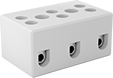 |
These ceramic terminal blocks keep their shape and strength at temperatures up to 1,200° F—over four times higher than standard blocks. Mount them to surfaces in ovens, kilns, and other heat-generating equipment.
Screw-Clamp-Terminal Wire Connection—The clamp flattens the wire to resist pullout and vibration better than screw terminals. For an even stronger and more conductive connection, crimp a terminal or wire ferrule onto the end of the wire.
Mounting Holes | ||||||||||||||||
|---|---|---|---|---|---|---|---|---|---|---|---|---|---|---|---|---|
No. of Circuits | For Wire Ga. | Wire Connection | Terminal Size | Terminal Ctr.-to-Ctr. | Lg. | Wd. | Ht. | Max. Temp., ° F | Material | Color | Dia. | No. of | Each | |||
300V AC/300V DC—20 amp per Circuit | ||||||||||||||||
| 1 | 24 to 12 | Screw Terminal | M3 | — | 7/16" | 15/16" | 3/4" | 1,200 | Ceramic | White | — | — | 5602T25 | 00000 | ||
| 2 | 24 to 12 | Screw Terminal | M3 | 5/16" | 11/16" | 15/16" | 3/4" | 1,200 | Ceramic | White | — | — | 5602T31 | 0000 | ||
| 2 | 24 to 12 | Screw Terminal | M3 | 1/2" | 15/16" | 15/16" | 3/4" | 1,200 | Ceramic | White | 0.14" | 2 | 5602T32 | 0000 | ||
| 3 | 24 to 12 | Screw Terminal | M3 | 5/16" | 1" | 15/16" | 3/4" | 1,200 | Ceramic | White | — | — | 5602T33 | 0000 | ||
| 3 | 24 to 12 | Screw Terminal | M3 | 1/2" | 1 7/16" | 15/16" | 3/4" | 1,200 | Ceramic | White | 0.14" | 2 | 5602T34 | 0000 | ||
300V AC/300V DC—30 amp per Circuit | ||||||||||||||||
| 1 | 22 to 10 | Screw Terminal | M3 | — | 1/2" | 1" | 3/4" | 1,200 | Ceramic | White | — | — | 5602T35 | 0000 | ||
| 2 | 22 to 10 | Screw Terminal | M3 | 9/16" | 1" | 1" | 3/4" | 1,200 | Ceramic | White | 0.14" | 2 | 5602T21 | 0000 | ||
| 3 | 22 to 10 | Screw Terminal | M3 | 9/16" | 1 5/8" | 1" | 3/4" | 1,200 | Ceramic | White | 0.14" | 2 | 5602T23 | 0000 | ||
| 4 | 22 to 10 | Screw Terminal | M3 | 5/16" | 1 9/16" | 13/16" | 5/8" | 1,200 | Ceramic | White | 0.14" | 1 | 5602T26 | 0000 | ||
300V AC/300V DC—65 amp per Circuit | ||||||||||||||||
| 2 | 18 to 6 | Screw Terminal | M3 | 11/16" | 1 1/4" | 1 1/8" | 15/16" | 1,200 | Ceramic | White | 0.14" | 2 | 5602T22 | 0000 | ||
| 3 | 18 to 6 | Screw Terminal | M3 | 11/16" | 1 7/8" | 1 1/16" | 15/16" | 1,200 | Ceramic | White | 0.14" | 2 | 5602T24 | 0000 | ||
600V AC/600V DC—20 amp per Circuit | ||||||||||||||||
| 2 | 20 to 12 | Screw-Clamp Terminal | No. 8 | 7/8" | 1 9/16" | 1 1/4" | 13/16" | 840 | Ceramic | Beige | 0.19" | 1 | 1322T11 | 00000 | ||
| 3 | 20 to 12 | Screw-Clamp Terminal | No. 8 | 7/8" | 2 7/16" | 1 1/4" | 13/16" | 840 | Ceramic | Beige | 0.19" | 2 | 1322T12 | 00000 | ||
Terminal Blocks for RTD and Thermocouple Connection Heads
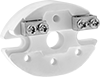 | 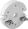 |
Oblong | Round |
These terminal blocks fit inside connection heads for thermocouples and RTD. Make sure the block has enough circuits for your probe, and use a wire that matches your probe type. You can insert stripped wire directly or attach a terminal to prevent damage from the fastener.
Mounting Slots | |||||||||||||||||
|---|---|---|---|---|---|---|---|---|---|---|---|---|---|---|---|---|---|
No. of Circuits | For Max. Wire Ga. | Wire Connection | Dia. | Ht. | Wd. | Dp. | For Thermocouple Wire Type | For RTD Probe Resistance, ohm | Max. Temp., ° F | Material | Ht. | Wd. | No. of | Each | |||
Oblong | |||||||||||||||||
| 2 | 14 | Screw Terminal | — | 1 3/8" | 2" | 1" | J, JX, K, KK, KX, T, TX | 100; 1,000 | 1,000 | Ceramic | 3/16" | 9/16" | 2 | 38705K82 | 000000 | ||
| 3 | 14 | Screw Terminal | — | 1 3/8" | 2" | 1" | J, JX, K, KK, KX, T, TX | 100; 1,000 | 1,000 | Ceramic | 3/16" | 9/16" | 2 | 38705K83 | 00000 | ||
| 4 | 14 | Screw Terminal | — | 1 3/8" | 2" | 1" | J, JX, K, KK, KX, T, TX | 100; 1,000 | 1,000 | Ceramic | 3/16" | 9/16" | 2 | 5927N11 | 00000 | ||
| 6 | 14 | Screw Terminal | — | 1 3/8" | 2" | 1" | J, JX, K, KK, KX, T, TX | 100; 1,000 | 1,000 | Ceramic | 3/16" | 9/16" | 2 | 5927N12 | 00000 | ||
Round | |||||||||||||||||
| 2 | 14 | Screw Terminal | 1 15/16" | — | — | 3/4" | J, JX, K, KK, KX, T, TX | 100; 1,000 | 1,000 | Ceramic | 3/16" | 5/16" | 2 | 5927N13 | 00000 | ||
| 3 | 14 | Screw Terminal | 1 15/16" | — | — | 3/4" | J, JX, K, KK, KX, T, TX | 100; 1,000 | 1,000 | Ceramic | 3/16" | 5/16" | 2 | 5927N14 | 00000 | ||
| 4 | 14 | Screw Terminal | 1 15/16" | — | — | 3/4" | J, JX, K, KK, KX, T, TX | 100; 1,000 | 1,000 | Ceramic | 3/16" | 5/16" | 2 | 5927N15 | 00000 | ||
| 6 | 14 | Screw Terminal | 1 15/16" | — | — | 3/4" | J, JX, K, KK, KX, T, TX | 100; 1,000 | 1,000 | Ceramic | 3/16" | 5/16" | 2 | 5927N16 | 00000 | ||
