


Filter by

Distance Measured
Component
Dial Indicator Size
RoHS
DFARS Specialty Metals
U.S.–Mexico–Canada Agreement (USMCA) Qualifying
Export Control Classification Number (ECCN)
Material
Contact Point Material
Hole Attachments for Starrett Continuous Dial Back Plunger Variance Indicators
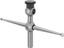 |
For Inside Hole Dp. | Mfr. Model No. | Each | ||
|---|---|---|---|---|
| 1 5/8" | 196F | 2217A17 | 000000 |
Economy Continuous Dial Back Plunger Variance Indicators with Calibration Certificate
 |  |
Side View |
Read the dial face from above—a spring-loaded plunger on the back of these indicators retracts and extends to measure objects. These indicators have a continuous dial numbered clockwise around the face, so it’s easy to see how much a dimension increases. Adjust the tolerance pointers as needed to easily tell which measurements fall outside your limits. They come with a calibration certificate traceable to NIST that states they’ve passed a test for accuracy.
Dial | Contact Point | |||||||||||||
|---|---|---|---|---|---|---|---|---|---|---|---|---|---|---|
Distance Measured | Measuring Increments | Accuracy | Dial Indicator Size | Mounting Stem Dia. | Dia. | Reading Inch | Dia. | Lg. | Mounting Thread Size | Includes | Each | |||
Stem Mount | ||||||||||||||
Plain Bearing | ||||||||||||||
| 0" to 0.200" | 0.001" | ±0.001" | AGD Group 1 | 1/4" | 1 5/8" | 0-100 | 1/8" 5/16" 1/2" | 0.244" 0.276" 0.335" | 4-48 | One 1/2" Dia. Contact Point (0.276" Lg.) One 1/8" Dia. Contact Point (0.335" Lg.) One 5/16" Dia. Contact Point (0.244" Lg.) | 5521N11 | 0000000 | ||
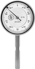
Starrett Continuous Dial Back Plunger Variance Indicators with Calibration Certificate
 |  |
Side View |
This indicator comes with a calibration certificate traceable to NIST that states it has passed a test for accuracy. The contact point is located on the back, which allows the dial face to be read from above. It has a continuous dial numbered clockwise around the face for direct measurements. A rugged design with few moving parts and highly sensitive, wear-resistant jeweled bearings give it a longer service life than other indicators. Rotate the dial face for viewing at multiple angles. The included tip adapter lets you use AGD-standard contact points that have 4-48 threads.
Dial | Contact Point | |||||||||||||
|---|---|---|---|---|---|---|---|---|---|---|---|---|---|---|
Distance Measured | Measuring Increments | Accuracy | Mounting Stem Dia. | Dia. | Reading Inch | Dia. | Lg. | Mounting Thread Size | Includes | Mfr. Model No. | Each | |||
Stem Mount | ||||||||||||||
Jeweled Bearing | ||||||||||||||
| 0" to 0.200" | 0.001" | ±0.001" | 1/4" | 1 3/8" | 0-100 | 1/8" 5/16" 1/2" | 1/4" | 0.127"-60 | One 1/8" Dia. Contact Point One 5/16" Dia. Contact Point One 1/2" Dia. Contact Point Tip Adapter | 196B1 | 2217A77 | 0000000 | ||

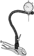
Economy Continuous Dial Back Plunger Variance Indicators with Clamp-On Holder
 |  |
Shown Installed with Included Double-Ended Lever | Side View |
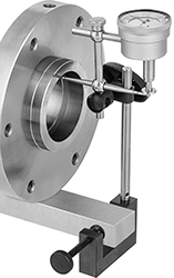
Clamp these indicators onto your machine or other surface—they take up less space on your surface than indicators with a magnetic or weighted base. They’re often mounted on a conveyor to measure variation on a material’s surface as it passes by. To measure, they have a spring-loaded plunger that retracts and extends as the surface varies. The plunger is on the back of the dial, so you can read the dial face from above. It’s easy to see how much a measurement increases, since the dial is continuous and numbered clockwise around the face. Adjust the tolerance pointers to mark measurements that fall outside your limits.
These indicators also come with a double-ended lever that measures how much a rotating tool wobbles as it spins. One end runs along the inner surface of a hole, while the other end presses against the spring-loaded plunger.
Dial | Contact Point | Base | Upright Post | ||||||||||||||||
|---|---|---|---|---|---|---|---|---|---|---|---|---|---|---|---|---|---|---|---|
Distance Measured | Measuring Increments | Accuracy | Dial Indicator Size | Indicator Mounting Stem Dia. | Dia. | Reading Inch | Dia. | Lg. | Mounting Thread Size | Lg. | Wd. | Dia. | Ht. | Clamping Distance | Includes | Each | |||
Stem Mount | |||||||||||||||||||
C-Clamp | |||||||||||||||||||
| 0.000" to 0.200" | 0.001" | ±0.001" | AGD Group 1 | 1/4" | 1 21/32" | 0-100 | 0.126" 0.315" 0.472" | 0.244" 0.276" 0.335" | 4-48 | 3/8" | 5 15/16" | 5/16" | 4 3/4" | 0" to 1 1/8" | Double-Ended Lever One 0.126" Dia. Contact Point (0.335" Lg.) One 0.315" Dia. Contact Point (0.244" Lg.) One 0.472" Dia. Contact Point (0.276" Lg.) | 6349N11 | 0000000 | ||
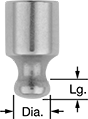
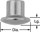
Contact Points for Starrett Continuous-Dial Back Plunger Variance Indicators
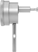
Starrett Continuous Dial Back Plunger Variance Indicators
| |
Side View |
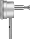
The contact point is located on the back of this indicator, which allows the dial face to be read from above. It has a continuous dial numbered clockwise around the face for direct measurements. A rugged design with few moving parts and highly sensitive, wear-resistant jeweled bearings give it a longer service life than other indicators. Rotate the dial face for viewing at multiple angles. The included tip adapter lets you use AGD-standard contact points that have 4-48 threads.
Dial | Contact Point | |||||||||||||
|---|---|---|---|---|---|---|---|---|---|---|---|---|---|---|
Distance Measured | Measuring Increments | Accuracy | Mounting Stem Dia. | Dia. | Reading Inch | Dia. | Lg. | Mounting Thread Size | Includes | Mfr. Model No. | Each | |||
Stem Mount | ||||||||||||||
Jeweled Bearing | ||||||||||||||
| 0" to 0.200" | 0.001" | ±0.001" | 1/4" | 1 3/8" | 0-100 | 1/8" 5/16" 1/2" | 1/4" | 0.127"-60 | One 1/8" Dia. Contact Point One 5/16" Dia. Contact Point One 1/2" Dia. Contact Point Tip Adapter | 196B1 | 2217A12 | 0000000 | ||
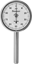
Electronic Back Plunger Variance Indicators with Calibration Certificate
 |  |
Dial View |
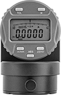
A contact point on the back makes it easy to read measurements on the LCD from above. The display also rotates 320°, so you can view it from most angles. These indicators have a spring-loaded plunger that retracts and extends to measure objects. They come with a calibration certificate traceable to NIST that states they’ve passed a test for accuracy.
To help you take measurements efficiently, these indicators come with multiple features. The go/no-go operation indicates when measurements fall outside your set tolerance. These indicators can measure TIR (total indicated runout), which determines the range of high and low spots of round parts. Zero-position memory, also known as absolute (ABS) positioning, retains the measuring position when the indicator is off. Start measuring at any point with the zero-set button. They have an SPC data output, so you can transfer data to a computer or data processor.
Distance Measured | Measuring Increments | Accuracy | Contact Point | ||||||||||||||
|---|---|---|---|---|---|---|---|---|---|---|---|---|---|---|---|---|---|
Inch | Metric, mm | Inch | Metric, mm | Inch | Metric | Dial Indicator Size | Mounting Stem Dia. | Dial Dia. | Dia. | Lg. | Mounting Thread Size | Batteries Included | SPC Data Output | Each | |||
Stem Mount | |||||||||||||||||
| 0" to 0.5" | 0 to 12.7 | 0.0005" | 0.01 | ±0.0015" | ±0.0381 mm | AGD Group 2 | 3/8" | 2 9/32" | 0.177" | 0.945" | 4-48 | Yes | Yes | 6345N11 | 0000000 | ||
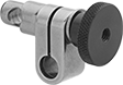
Holder Posts for Starrett Continuous Dial Back Plunger Variance Indicators
Economy Dial Plunger Variance Indicators with Clamp-On Holder
 | 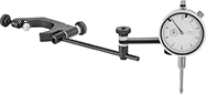 | |
Side View | Plier Clamp | C-Clamp |
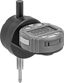
Often used where space is tight or there’s not much of a surface for mounting, the clamp on these indicators fits where a weighted or magnetic base can’t. The clamp also gives you the option to directly mount these indicators to a machine or the piece you’re measuring. With the ball-and-socket segmented arm, you can adjust the indicator to nearly any position to keep it from obstructing what you're measuring. Pull the lever to lock the arm in place when you're done. To measure objects, these indicators have a spring-loaded plunger that retracts and extends as the surface varies. It’s easy to see how much a measurement increases, since the dial is continuous and numbered clockwise around the face. Adjust the tolerance pointers to mark measurements that fall outside your limits.
Plier Clamp—Indicators with a plier clamp work on most thin, flat surfaces.
C-Clamp—Indicators with a C-clamp apply less pressure than indicators with a plier clamp, so there’s less risk of damaging a workpiece.
Dial | Contact Point | Arm | ||||||||||||||||
|---|---|---|---|---|---|---|---|---|---|---|---|---|---|---|---|---|---|---|
Distance Measured | Measuring Increments | Accuracy | Dial Indicator Size | Indicator Mounting Stem Dia. | Mounting Lug Hole Dia. | Dia. | Reading Inch | Dia. | Lg. | Mounting Thread Size | Clamping Distance | Lg. | Dia. | Type | Each | |||
Lug Mount, Stem Mount | ||||||||||||||||||
Plier Clamp | ||||||||||||||||||
| 0.000" to 1.000" | 0.001" | ±0.001" | AGD Group 1 | 3/8" | 1/4" | 2" | 0-100 | 0.197" | 0.236" | 4-48 | 0" to 1 3/4" | 12" | 0.625" | Flexible | 6373N12 | 000000 | ||
C-Clamp | ||||||||||||||||||
| 0.000" to 1.000" | 0.001" | ±0.001" | AGD Group 1 | 3/8" | 1/4" | 2" | 0-100 | 0.197" | 0.236" | 4-48 | 0" to 6" | 12" | 0.625" | Flexible | 6373N11 | 00000 | ||
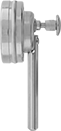
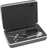
Starrett Continuous Dial Back Plunger Variance Indicator Sets
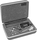 | | |
Side View |
The contact point is located on the back of this indicator, which allows the dial face to be read from above. It has a continuous dial numbered clockwise around the face for direct measurements. A rugged design with few moving parts and highly sensitive, wear-resistant jeweled bearings give it a longer service life than other indicators. Rotate the dial face for viewing at multiple angles.
Indicators | Replacement Variance Indicator Cases | ||||||||||||||
|---|---|---|---|---|---|---|---|---|---|---|---|---|---|---|---|
Dial | Contact Point | ||||||||||||||
Distance Measured | Measuring Increments | Accuracy | Mounting Stem Dia. | Dia. | Reading Inch | Dia. | Lg. | Mounting Thread Size | Includes | Mfr. Model No. | Each | Each | |||
| 0" to 0.200" | 0.001" | ±0.001" | 1/4" | 1 7/16" | 0-100 | 1/8" 5/16" 1/2" | 1/4" | 0.127"-60 | C-Clamp with Post Height Gauge/Tool Post Attachment Hole Attachment One 1/8" Dia. Contact Point One 5/16" Dia. Contact Point One 1/2" Dia. Contact Point Swivel Clamp | 196A1Z | 2217A11 | 0000000 | 4378N11 | 000000 | |
Contact Point Adapters for Starrett Continuous-Dial Back Plunger Variance Indicators
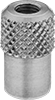 |
For Contact Point Thread Size | Mfr. Model No. | Each | ||
|---|---|---|---|---|
| 4-48 | 196R | 2217A32 | 00000 |
Antimagnetic Starrett Continuous Dial Back Plunger Variance Indicator Sets
 | | |
Side View |
Use the indicator in this set near magnetic chucks and other equipment with a magnetic field. The contact point is located on the back, which allows the dial face to be read from above. It has a continuous dial numbered clockwise around the face for direct measurements. A rugged design with few moving parts and highly sensitive, wear-resistant jeweled bearings give it a longer service life than other indicators. Rotate the dial face for viewing at multiple angles.
Indicators | Replacement Variance Indicator Cases | ||||||||||||||
|---|---|---|---|---|---|---|---|---|---|---|---|---|---|---|---|
Dial | Contact Point | ||||||||||||||
Distance Measured | Measuring Increments | Accuracy | Mounting Stem Dia. | Dia. | Reading Inch | Dia. | Lg. | Mounting Thread Size | Includes | Mfr. Model No. | Each | Each | |||
| 0" to 0.200" | 0.001" | ±0.001" | 1/4" | 1 7/16" | 0-100 | 1/8" 5/16" 1/2" | 1/4" | 0.127"-60 | C-Clamp with Post Height Gauge/Tool Post Attachment Hole Attachment One 1/8" Dia. Contact Point One 5/16" Dia. Contact Point One 1/2" Dia. Contact Point Swivel Clamp | 196A6Z | 2217A61 | 0000000 | 4378N11 | 000000 | |
Clamps for Starrett Continuous-Dial Back Plunger Variance Indicators
