


Positioning Slides
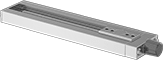
Use these slides in a variety of manual-positioning applications for laboratory and production equipment as well as for positioning parts for drilling, fastening, assembly, and measuring. Their Rulon sleeve bearings allow smooth movement in dirty environments.
Travel distance per turn, also known as screw lead, is the distance the carriage moves with one revolution of the handle.
Note: Capacities listed are for horizontal mounting. When mounted vertically, the load capacity is cut in half.
O'all | Carriage | Handle | Carriage Mounting | Base Mounting | ||||||||||||||
|---|---|---|---|---|---|---|---|---|---|---|---|---|---|---|---|---|---|---|
| Travel Lg. | Travel Distance per Turn | Accuracy for Travel Distance per Turn | Ht. | Wd. | Lg. | Wd. | Lg. | Type | Dia. | Overhang | Max. Temp., °F | No. of Holes | Hole Thread Size | No. of Holes | For Fastener Thread Size | Mounting Fasteners Included | Each | |
Aluminum Carriage and Base | ||||||||||||||||||
15 lbs. Static Load Capacity | ||||||||||||||||||
| 1.5" | 0.05" | 0.0007" per in. | 0.56" | 1.5" | 4.16" | 0.62" | 1.5" | Dial | 0.61" | __ | 180° | 4 | 6-32 | 2 | 8-32 | No | 0000000 | 0000000 |
| 4.5" | 0.05" | 0.0007" per in. | 0.56" | 1.5" | 7.16" | 0.62" | 1.5" | Dial | 0.61" | __ | 180° | 4 | 6-32 | 2 | 8-32 | No | 0000000 | 000000 |
| 7.5" | 0.05" | 0.0007" per in. | 0.56" | 1.5" | 10.16" | 0.62" | 1.5" | Dial | 0.61" | __ | 180° | 4 | 6-32 | 3 | 8-32 | No | 0000000 | 000000 |
| 10.5" | 0.05" | 0.0007" per in. | 0.56" | 1.5" | 13.16" | 0.62" | 1.5" | Dial | 0.61" | __ | 180° | 4 | 6-32 | 4 | 8-32 | No | 0000000 | 000000 |
30 lbs. Static Load Capacity | ||||||||||||||||||
| 1.5" | 0.05" | 0.0007" per in. | 0.81" | 2.5" | 6.72" | 1.25" | 2.5" | Hand Wheel | 1.75" | 0.44" | 180° | 4 | 8-32 | 2 | 10-32 | No | 0000000 | 000000 |
| 3.5" | 0.05" | 0.0007" per in. | 0.81" | 2.5" | 8.72" | 1.25" | 2.5" | Hand Wheel | 1.75" | 0.44" | 180° | 4 | 8-32 | 2 | 10-32 | No | 0000000 | 000000 |
| 6.5" | 0.05" | 0.0007" per in. | 0.81" | 2.5" | 11.72" | 1.25" | 2.5" | Hand Wheel | 1.75" | 0.44" | 180° | 4 | 8-32 | 3 | 10-32 | No | 0000000 | 000000 |
| 9.5" | 0.05" | 0.0007" per in. | 0.81" | 2.5" | 14.72" | 1.25" | 2.5" | Hand Wheel | 1.75" | 0.44" | 180° | 4 | 8-32 | 4 | 10-32 | No | 0000000 | 000000 |
| 12.5" | 0.05" | 0.0007" per in. | 0.81" | 2.5" | 17.72" | 1.25" | 2.5" | Hand Wheel | 1.75" | 0.44" | 180° | 4 | 8-32 | 5 | 10-32 | No | 0000000 | 000000 |
100 lbs. Static Load Capacity | ||||||||||||||||||
| 2" | 0.1" | 0.0007" per in. | 1.06" | 4" | 8.73" | 2.35" | 4" | Hand Wheel | 1.75" | 0.24" | 180° | 4 | 10-32 | 2 | 1/4"-20 | No | 0000000 | 000000 |
| 5" | 0.1" | 0.0007" per in. | 1.06" | 4" | 11.73" | 2.35" | 4" | Hand Wheel | 1.75" | 0.24" | 180° | 4 | 10-32 | 3 | 1/4"-20 | No | 0000000 | 000000 |
| 8" | 0.1" | 0.0007" per in. | 1.06" | 4" | 14.73" | 2.35" | 4" | Hand Wheel | 1.75" | 0.24" | 180° | 4 | 10-32 | 4 | 1/4"-20 | No | 0000000 | 000000 |
| 11" | 0.1" | 0.0007" per in. | 1.06" | 4" | 17.73" | 2.35" | 4" | Hand Wheel | 1.75" | 0.24" | 180° | 4 | 10-32 | 5 | 1/4"-20 | No | 0000000 | 000000 |
| 14" | 0.1" | 0.0007" per in. | 1.06" | 4" | 20.73" | 2.35" | 4" | Hand Wheel | 1.75" | 0.24" | 180° | 4 | 10-32 | 6 | 1/4"-20 | No | 0000000 | 000000 |
| 20" | 0.1" | 0.0007" per in. | 1.06" | 4" | 26.73" | 2.35" | 4" | Hand Wheel | 1.75" | 0.24" | 180° | 4 | 10-32 | 8 | 1/4"-20 | No | 0000000 | 00000000 |
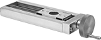
Precision Positioning Slides
A linear scale and micrometer-like hand wheel measure travel distance in increments of 0.001". Rulon sleeve bearings allow these slides to move smoothly, even in dirty environments. Use them in a variety of manual-positioning applications for laboratory and production equipment as well as for positioning parts for drilling, fastening, assembly, and measuring.
Travel distance per turn, also known as screw lead, is the distance the carriage moves with one revolution of the handle.
Note: Capacities listed are for horizontal mounting. When mounted vertically, the load capacity is cut in half.
O'all | Carriage | Handle | Carriage Mounting | Base Mounting | |||||||||||||||
|---|---|---|---|---|---|---|---|---|---|---|---|---|---|---|---|---|---|---|---|
| Travel Lg. | Travel Distance per Turn | Accuracy for Travel Distance per Turn | Ht. | Wd. | Lg. | Wd. | Lg. | Type | Dia. | Overhang | Linear Scale Graduation Marks | Max. Temp., °F | No. of Holes | Hole Thread Size | No. of Holes | For Fastener Thread Size | Mounting Fasteners Included | Each | |
Aluminum Carriage and Base | |||||||||||||||||||
15 lbs. Static Load Capacity | |||||||||||||||||||
| 1.5" | 0.05" | 0.00015" per in. | 0.61" | 1.5" | 5.6" | 0.62" | 1.5" | Hand Wheel | 1.75" | 0.59" | 0.025" | 180° | 4 | 6-32 | 2 | 8-32 | No | 0000000 | 0000000 |
| 4.5" | 0.05" | 0.00015" per in. | 0.56" | 1.5" | 8.6" | 0.62" | 1.5" | Hand Wheel | 1.75" | 0.59" | 0.025" | 180° | 4 | 6-32 | 2 | 8-32 | No | 0000000 | 000000 |
| 7.5" | 0.05" | 0.00015" per in. | 0.61" | 1.5" | 11.6" | 0.62" | 1.5" | Hand Wheel | 1.75" | 0.59" | 0.025" | 180° | 4 | 6-32 | 3 | 8-32 | No | 0000000 | 000000 |
| 10.5" | 0.05" | 0.00015" per in. | 0.61" | 1.5" | 14.6" | 0.62" | 1.5" | Hand Wheel | 1.75" | 0.59" | 0.025" | 180° | 4 | 6-32 | 4 | 8-32 | No | 0000000 | 000000 |
30 lbs. Static Load Capacity | |||||||||||||||||||
| 1.5" | 0.05" | 0.00015" per in. | 0.81" | 2.5" | 6.74" | 1.25" | 2.5" | Hand Wheel | 1.75" | 0.44" | 0.025" | 180° | 4 | 8-32 | 2 | 10-32 | No | 0000000 | 000000 |
| 3.5" | 0.05" | 0.00015" per in. | 0.81" | 2.5" | 8.74" | 1.25" | 2.5" | Hand Wheel | 1.75" | 0.44" | 0.025" | 180° | 4 | 8-32 | 2 | 10-32 | No | 0000000 | 000000 |
| 6.5" | 0.05" | 0.00015" per in. | 0.81" | 2.5" | 11.74" | 1.25" | 2.5" | Hand Wheel | 1.75" | 0.44" | 0.025" | 180° | 4 | 8-32 | 3 | 10-32 | No | 0000000 | 000000 |
100 lbs. Static Load Capacity | |||||||||||||||||||
| 2" | 0.1" | 0.00015" per in. | 1.06" | 4" | 9.41" | 2.35" | 4" | Hand Wheel | 1.75" | 0.24" | 0.025" | 180° | 4 | 10-32 | 2 | 1/4"-20 | No | 0000000 | 000000 |
| 5" | 0.1" | 0.00015" per in. | 1.06" | 4" | 12.41" | 2.35" | 4" | Hand Wheel | 1.75" | 0.24" | 0.025" | 180° | 4 | 10-32 | 3 | 1/4"-20 | No | 0000000 | 00000000 |
| 8" | 0.1" | 0.00015" per in. | 1.06" | 4" | 15.41" | 2.35" | 4" | Hand Wheel | 1.75" | 0.24" | 0.025" | 180° | 4 | 10-32 | 4 | 1/4"-20 | No | 0000000 | 00000000 |
| 11" | 0.1" | 0.00015" per in. | 1.06" | 4" | 18.41" | 2.35" | 4" | Hand Wheel | 1.75" | 0.24" | 0.025" | 180° | 4 | 10-32 | 5 | 1/4"-20 | No | 0000000 | 00000000 |
| 14" | 0.1" | 0.00015" per in. | 1.06" | 4" | 21.41" | 2.35" | 4" | Hand Wheel | 1.75" | 0.24" | 0.025" | 180° | 4 | 10-32 | 6 | 1/4"-20 | No | 0000000 | 00000000 |
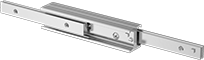
Telescoping Slides
Good for use in pick-and-place applications, machine tool doors, and telescopic industrial press arms, these rugged slides are designed to carry heavy loads.
Note: Capacities listed are for side mounting. If mounted horizontally or upside down, load capacities are 70% of those listed.

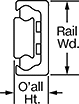
Carriage Mounting | Rail Mounting | ||||||||||
|---|---|---|---|---|---|---|---|---|---|---|---|
| Rail Lg., mm | Travel Lg., mm | Dynamic Load Cap., lbs. | O'all Ht., mm | Max. Temp., °F | No. of Holes | Hole Thread Size | No. of Holes | For Fastener Thread Size | Mounting Fasteners Included | Each | |
Zinc-Plated Steel Carriage and Steel Rail | |||||||||||
22 mm Rail Wd. | |||||||||||
| 130 | 76 | 70 | 11 | 335° | 2 | M4 | 2 | M4 | No | 0000000 | 0000000 |
| 210 | 111 | 160 | 11 | 335° | 3 | M4 | 3 | M4 | No | 0000000 | 000000 |
| 370 | 196 | 287 | 11 | 335° | 5 | M4 | 5 | M4 | No | 0000000 | 000000 |
28 mm Rail Wd. | |||||||||||
| 290 | 148 | 434 | 13 | 335° | 4 | M5 | 4 | M5 | No | 0000000 | 000000 |
| 450 | 232 | 664 | 13 | 335° | 6 | M5 | 6 | M5 | No | 0000000 | 000000 |
| 610 | 315 | 893 | 13 | 335° | 8 | M5 | 8 | M5 | No | 0000000 | 000000 |
| 770 | 399 | 1,123 | 13 | 335° | 10 | M5 | 10 | M5 | No | 0000000 | 000000 |
| 930 | 475 | 1,424 | 13 | 335° | 12 | M5 | 12 | M5 | No | 0000000 | 000000 |
| 1,010 | 517 | 1,539 | 13 | 335° | 13 | M5 | 13 | M5 | No | 0000000 | 000000 |
43 mm Rail Wd. | |||||||||||
| 610 | 313 | 1,666 | 22 | 335° | 8 | M8 | 8 | M8 | No | 00000000 | 000000 |
| 930 | 483 | 2,485 | 22 | 335° | 12 | M8 | 12 | M8 | No | 00000000 | 000000 |
| 1,010 | 518 | 2,795 | 22 | 335° | 13 | M8 | 13 | M8 | No | 00000000 | 000000 |
| 1,330 | 688 | 3,613 | 22 | 335° | 17 | M8 | 17 | M8 | No | 00000000 | 000000 |
| 1,490 | 758 | 4,236 | 22 | 335° | 19 | M8 | 19 | M8 | No | 00000000 | 000000 |
Chrome-Plated Steel Carriage and Chrome-Plated Steel Rail | |||||||||||
35 mm Rail Wd. | |||||||||||
| 210 | 129 | 578 | 17 | 212° | 3 | M6 | 3 | M6 | No | 0000000 | 000000 |
| 290 | 158 | 898 | 17 | 212° | 4 | M6 | 4 | M6 | No | 0000000 | 000000 |
| 370 | 200 | 967 | 17 | 212° | 5 | M6 | 5 | M6 | No | 0000000 | 000000 |
| 450 | 254 | 895 | 17 | 212° | 6 | M6 | 6 | M6 | No | 0000000 | 000000 |
| 530 | 284 | 1,047 | 17 | 212° | 7 | M6 | 7 | M6 | No | 0000000 | 000000 |
| 610 | 326 | 1,072 | 17 | 212° | 8 | M6 | 8 | M6 | No | 0000000 | 000000 |
| 690 | 367 | 1,094 | 17 | 212° | 9 | M6 | 9 | M6 | No | 0000000 | 000000 |
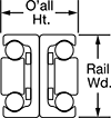
Carriage Mounting | |||||||||
|---|---|---|---|---|---|---|---|---|---|
| Rail Lg., mm | Travel Lg., mm | Dynamic Load Cap., lbs. | O'all Ht., mm | Max. Temp., °F | No. of Holes | Hole Thread Size | Mounting Fasteners Included | Each | |
Zinc-Plated Steel Carriage and Zinc-Plated Steel Rail | |||||||||
28 mm Rail Wd. | |||||||||
| 130 | 148 | 52 | 26 | 335° | 2 | M5 | No | 0000000 | 0000000 |
| 210 | 232 | 97 | 26 | 335° | 3 | M5 | No | 0000000 | 000000 |
| 290 | 296 | 172 | 26 | 335° | 4 | M5 | No | 0000000 | 000000 |
| 450 | 464 | 262 | 26 | 335° | 6 | M5 | No | 0000000 | 000000 |
| 530 | 548 | 248 | 26 | 335° | 7 | M5 | No | 0000000 | 000000 |
| 610 | 633 | 214 | 26 | 335° | 8 | M5 | No | 0000000 | 000000 |
43 mm Rail Wd. | |||||||||
| 370 | 416 | 292 | 44 | 335° | 5 | M8 | No | 0000000 | 000000 |
| 450 | 486 | 410 | 44 | 335° | 6 | M8 | No | 0000000 | 000000 |
| 530 | 556 | 533 | 44 | 335° | 7 | M8 | No | 0000000 | 000000 |
| 610 | 626 | 659 | 44 | 335° | 8 | M8 | No | 0000000 | 000000 |
| 690 | 726 | 694 | 44 | 335° | 9 | M8 | No | 0000000 | 000000 |
| 850 | 866 | 640 | 44 | 335° | 11 | M8 | No | 0000000 | 00000000 |
| 1,090 | 1,106 | 503 | 44 | 335° | 14 | M8 | No | 0000000 | 00000000 |
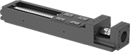
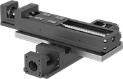
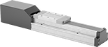
Positioning Slides for Stepper Motors
Add your own stepper motor and controller to precisely move the ball screw and carriage smoothly at high speeds, like a head on an inkjet printer. With a repeatability of ± 0.01 mm—thinner than a strand of hair—the carriage hits the same spot every time. These positioning slides work well for automated assemblies and other applications that require fine, repeatable motion control.
The carriage rides along the inside of the rail, making these slides more compact than traditional carriages and guide rails. Made of steel with a U-shaped rail, these slides resist twisting forces that could affect their positioning. This also means they can be installed with only one end supported or with both ends overhanging. The same load rating applies no matter how the slides are oriented.
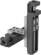
Two-axis mounting plates (sold separately) secure two slides together for motion along two axes.
Travel distance per turn, also known as screw lead, is how far the carriage moves with one rotation of the ball screw.
Dynamic Load Capacity, lbs. | Overall | Carriage | |||||||||||||||
|---|---|---|---|---|---|---|---|---|---|---|---|---|---|---|---|---|---|
| Stroke Lg., mm | Horizontal | Vertical | Max. Speed, mm/s | Travel Distance per Turn, mm | Repeatability, mm | For Shaft Dia. | For Max. Motor Speed, rpm | For Max. Motor Torque, in.-oz. | Lg., mm | Wd., mm | Ht., mm | Lg., mm | Wd., mm | Bearing Type | Base Material | Each | |
For NEMA 14 Motor Frame Size | |||||||||||||||||
| 30 | 148 | 148 | 100 | 1 | ±0.01 | 5mm | 6,000 | 29.3 | 166 | 40 | 42 | 46 | 23 | Ball | Steel | 00000000 | 0000000 |
| 80 | 148 | 148 | 100 | 1 | ±0.01 | 5mm | 6,000 | 29.3 | 216 | 40 | 42 | 46 | 23 | Ball | Steel | 00000000 | 00000000 |
| 110 | 528 | 528 | 200 | 2 | ±0.01 | 5mm | 6,000 | 88.1 | 276 | 50 | 36 | 47.4 | 31 | Ball | Steel | 00000000 | 00000000 |
| 130 | 148 | 148 | 100 | 1 | ±0.01 | 5mm | 6,000 | 29.3 | 266 | 40 | 42 | 46 | 23 | Ball | Steel | 00000000 | 00000000 |
For NEMA 17 Motor Frame Size | |||||||||||||||||
| 100 | 402 | 402 | 470 | 6 | ±0.01 | 5mm | 4,700 | 176 | 277 | 60 | 44.5 | 76 | 37.4 | Ball | Steel | 00000000 | 00000000 |
| 110 | 528 | 528 | 200 | 2 | ±0.01 | 5mm | 6,000 | 88.1 | 276.5 | 50 | 42 | 47.4 | 31 | Ball | Steel | 00000000 | 00000000 |
| 160 | 528 | 528 | 200 | 2 | ±0.01 | 5mm | 6,000 | 88.1 | 326.5 | 50 | 42 | 47.4 | 31 | Ball | Steel | 00000000 | 00000000 |
| 200 | 402 | 402 | 470 | 6 | ±0.01 | 5mm | 4,700 | 176 | 377 | 60 | 44.5 | 76 | 37.4 | Ball | Steel | 00000000 | 00000000 |
| 210 | 528 | 528 | 200 | 2 | ±0.01 | 5mm | 6,000 | 88.1 | 376.5 | 50 | 42 | 47.4 | 31 | Ball | Steel | 00000000 | 00000000 |
For NEMA 23 Motor Frame Size | |||||||||||||||||
| 100 | 402 | 402 | 470 | 6 | ±0.01 | 1/4" | 4,700 | 176 | 280 | 60 | 56.4 | 76 | 37.4 | Ball | Steel | 00000000 | 00000000 |
| 200 | 402 | 402 | 470 | 6 | ±0.01 | 1/4" | 4,700 | 176 | 380 | 60 | 56.4 | 76 | 37.4 | Ball | Steel | 00000000 | 00000000 |
| 300 | 395 | 395 | 790 | 10 | ±0.01 | 1/4" | 6,000 | 176 | 480 | 60 | 56.4 | 76 | 37.4 | Ball | Steel | 00000000 | 00000000 |
| 400 | 395 | 395 | 790 | 10 | ±0.01 | 1/4" | 5,880 | 176 | 580 | 60 | 56.4 | 76 | 37.4 | Ball | Steel | 00000000 | 00000000 |
| 500 | 395 | 395 | 650 | 10 | ±0.01 | 1/4" | 3,900 | 176 | 680 | 60 | 56.4 | 76 | 37.4 | Ball | Steel | 00000000 | 00000000 |
| 600 | 395 | 395 | 470 | 10 | ±0.01 | 1/4" | 2,820 | 176 | 780 | 60 | 56.4 | 76 | 37.4 | Ball | Steel | 00000000 | 00000000 |
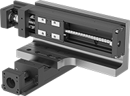
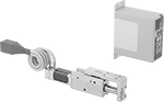
Electric Positioning Slides with Automated Controls
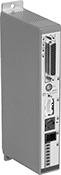
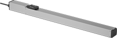
With an included controller and an integrated stepper motor, these slides are a complete precision motion control system. The stepper motor moves the low-friction ball screw and carriage smoothly at high speeds, similar to an inkjet printer head. To make sure the carriage is in the right place, the built-in encoder sends data to the controller. At ± 0.02 mm, these slides have a repeatability thinner than a single strand of hair, so the carriage hits the same spot every time. They work well in automated assemblies and other processes requiring accurate, repeatable motion.
For the initial setup, program the slides using the free, downloadable software, THK D-STEP. No coding necessary—simply enter the target position, speed, and acceleration for up to 16 different slides. This software also records position, speed, and motor current data, so you can monitor performance, optimize motion, and troubleshoot issues.
After the initial setup, the controller stores and runs sequences of up to 512 unique steps on its own. The controller also communicates with other devices such as PLCs, switches, and sensors. This means it can be integrated into a larger automated system to react to or trigger other processes as the carriage moves.
Travel distance per turn, also known as screw lead, is how far the carriage moves with one rotation of the ball screw.
Dynamic load capacity is the maximum load slides can move. If you increase the speed, the dynamic load capacity decreases. Use a load-speed chart to confirm which slides will work for your application. Click on a part number and select "Product Detail" to view the chart.
Dynamic Load Capacity, lbs. | Overall | Carriage | ||||||||||||||
|---|---|---|---|---|---|---|---|---|---|---|---|---|---|---|---|---|
| Horizontal | Vertical | Max. Speed, mm/s | Travel Distance per Turn, mm | Repeatability, mm | Lg., mm | Wd., mm | Ht., mm | Lg., mm | Wd., mm | Bearing Type | Base Material | Full Load Current | Voltage | Operating System Compatibility | Each | |
100 mm Stroke Length | ||||||||||||||||
| 2 | 1 | 300 | 6 | ±0.02 | 346 | 32 | 39 | 66.4 | 28 | Ball | Aluminum | 1.5A | 24V DC | Windows XP or Later | 0000000 | 000000000 |
| 13 | 4 | 500 | 12 | ±0.02 | 356 | 50 | 55 | 71 | 44 | Ball | Aluminum | 1.5A | 24V DC | Windows XP or Later | 0000000 | 00000000 |
| 22 | 11 | 300 | 6 | ±0.02 | 356 | 50 | 55 | 71 | 44 | Ball | Aluminum | 1.5A | 24V DC | Windows XP or Later | 0000000 | 00000000 |
200 mm Stroke Length | ||||||||||||||||
| 2 | 1 | 300 | 6 | ±0.02 | 446 | 32 | 39 | 66.4 | 28 | Ball | Aluminum | 1.5A | 24V DC | Windows XP or Later | 0000000 | 00000000 |
| 13 | 4 | 500 | 12 | ±0.02 | 456 | 50 | 55 | 71 | 44 | Ball | Aluminum | 1.5A | 24V DC | Windows XP or Later | 0000000 | 00000000 |
| 22 | 11 | 300 | 6 | ±0.02 | 456 | 50 | 55 | 71 | 44 | Ball | Aluminum | 1.5A | 24V DC | Windows XP or Later | 0000000 | 00000000 |
300 mm Stroke Length | ||||||||||||||||
| 2 | 1 | 300 | 6 | ±0.02 | 546 | 32 | 39 | 66.4 | 28 | Ball | Aluminum | 1.5A | 24V DC | Windows XP or Later | 0000000 | 00000000 |
| 13 | 4 | 500 | 12 | ±0.02 | 556 | 50 | 55 | 71 | 44 | Ball | Aluminum | 1.5A | 24V DC | Windows XP or Later | 0000000 | 00000000 |
| 22 | 11 | 300 | 6 | ±0.02 | 556 | 50 | 55 | 71 | 44 | Ball | Aluminum | 1.5A | 24V DC | Windows XP or Later | 0000000 | 00000000 |
400 mm Stroke Length | ||||||||||||||||
| 13 | 4 | 500 | 12 | ±0.02 | 656 | 50 | 55 | 71 | 44 | Ball | Aluminum | 1.5A | 24V DC | Windows XP or Later | 0000000 | 00000000 |
| 22 | 11 | 300 | 6 | ±0.02 | 656 | 50 | 55 | 71 | 44 | Ball | Aluminum | 1.5A | 24V DC | Windows XP or Later | 0000000 | 00000000 |
500 mm Stroke Length | ||||||||||||||||
| 13 | 4 | 500 | 12 | ±0.02 | 756 | 50 | 55 | 71 | 44 | Ball | Aluminum | 1.5A | 24V DC | Windows XP or Later | 0000000 | 00000000 |
| 22 | 11 | 300 | 6 | ±0.02 | 756 | 50 | 55 | 71 | 44 | Ball | Aluminum | 1.5A | 24V DC | Windows XP or Later | 0000000 | 00000000 |
600 mm Stroke Length | ||||||||||||||||
| 13 | 4 | 460 | 12 | ±0.02 | 862 | 60 | 60.5 | 75 | 53 | Ball | Aluminum | 1.5A | 24V DC | Windows XP or Later | 0000000 | 00000000 |
| 22 | 11 | 230 | 6 | ±0.02 | 862 | 60 | 60.5 | 75 | 53 | Ball | Aluminum | 1.5A | 24V DC | Windows XP or Later | 0000000 | 00000000 |
Clean Room Electric Positioning Slides
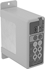
Prevent dust from circulating while precisely positioning parts for drilling, fastening, assembly, and measuring. These slides have a built-in vacuum port to remove fine particles that could damage electronics or contaminate batches in clean rooms. Because they have an integrated stepper motor with an included controller, you can adjust the speed, timing, and positioning with no extra software required. At ± 0.02 mm, these slides have a repeatability thinner than a single sheet of paper, so the carriage hits the same spot every time. Unlike air-powered actuators, they’ll hold their position even if power fails. They’re also more energy efficient.
Dynamic load capacity is the maximum load slides can move. If you increase the speed, the dynamic load capacity decreases. Use a load-speed chart to confirm which slides will work for your application. Click on a part number and select "Product Detail" to view the chart.
Maximum speed is how fast the slide will move under no-load conditions. If you increase the load, the slide speed will decrease.
Travel distance per full step determines the control you have over the slide’s positioning. The smaller the measurement, the finer positioning control you have.
Travel distance per turn, also known as screw lead, is how far the carriage moves with one rotation of the ball screw.
Dynamic Load Cap., lbs. | Travel Distance per | Overall | Carriage | ||||||||||||||
|---|---|---|---|---|---|---|---|---|---|---|---|---|---|---|---|---|---|
| Horizontal | Vertical | Max. Speed, mm/s | Full Step, mm | Turn, mm | Repeatability, mm | Lg., mm | Wd., mm | Ht., mm | Lg., mm | Wd., mm | Bearing Type | Base Material | Full Load Current | Voltage | Environmental Rating | Each | |
200 mm Stroke Length | |||||||||||||||||
| 110 | 44 | 250 | 0.08 | 8 | ±0.02 | 541 | 70 | 84 | 122 | 60 | Ball | Aluminum | 5A | 24V DC | Fed. Std. Class 10, ISO Class 4 | 0000000 | 000000000 |
| 143 | 50 | 250 | 0.1 | 10 | ±0.02 | 614.5 | 90 | 85.5 | 170 | 74 | Ball | Aluminum | 5A | 24V DC | Fed. Std. Class 10, ISO Class 4 | 0000000 | 00000000 |
300 mm Stroke Length | |||||||||||||||||
| 110 | 44 | 250 | 0.08 | 8 | ±0.02 | 641 | 70 | 84 | 122 | 60 | Ball | Aluminum | 5A | 24V DC | Fed. Std. Class 10, ISO Class 4 | 0000000 | 00000000 |
400 mm Stroke Length | |||||||||||||||||
| 110 | 44 | 250 | 0.08 | 8 | ±0.02 | 741 | 70 | 84 | 122 | 60 | Ball | Aluminum | 5A | 24V DC | Fed. Std. Class 10, ISO Class 4 | 0000000 | 00000000 |
| 143 | 50 | 250 | 0.1 | 10 | ±0.02 | 814.5 | 90 | 85.5 | 170 | 74 | Ball | Aluminum | 5A | 24V DC | Fed. Std. Class 10, ISO Class 4 | 0000000 | 00000000 |
600 mm Stroke Length | |||||||||||||||||
| 143 | 50 | 250 | 0.1 | 10 | ±0.02 | 1,014.5 | 90 | 85.5 | 170 | 74 | Ball | Aluminum | 5A | 24V DC | Fed. Std. Class 10, ISO Class 4 | 0000000 | 00000000 |
800 mm Stroke Length | |||||||||||||||||
| 143 | 50 | 250 | 0.1 | 10 | ±0.02 | 1,214.5 | 90 | 85.5 | 170 | 74 | Ball | Aluminum | 5A | 24V DC | Fed. Std. Class 10, ISO Class 4 | 0000000 | 00000000 |
Miniature Electric Actuators with Automated Controls
Smaller than any other actuator in our offering, these actuators’ short stroke length makes them good for automating fine, precise adjustments. They’re often used for aligning, pressing, and diverting. They come with an all-in-one motion control system to set the speed, timing, and position with buttons—no programming is required.
Rod-style actuators have threads on the front of the rod.
Slide table-style actuators give you setup flexibility, since you can mount equipment on top or in front. Mount on top to reduce the space you need to move a full stroke length.
Lg. | Dynamic Load Capacity, lbs. | Extension Rod | |||||||||||||
|---|---|---|---|---|---|---|---|---|---|---|---|---|---|---|---|
| Stroke | Retracted | Voltage | Full Load Current, A | Horizontal | Vertical | Max. Speed, in./sec. | Repeatability, mm | Extension Rod Type | End Type | Dia. | Thread Size | Thread Pitch, mm | Environmental Rating | Each | |
Rod Actuator Style | |||||||||||||||
| 1" | 5 3/8" | 24V DC | 0.9 | 2 | 1 | 5.91 | ±0.05 | Nonrotating | Threaded | 0.47" | M4 | 0.7 | IP40 | 0000000 | 0000000 |
| 1" | 5 7/8" | 24V DC | 2.2 | 4 | 3 | 7.87 | ±0.05 | Nonrotating | Threaded | 0.55" | M5 | 0.8 | IP40 | 0000000 | 000000 |
| 2" | 6 1/2" | 24V DC | 0.9 | 2 | 1 | 5.91 | ±0.05 | Nonrotating | Threaded | 0.47" | M4 | 0.7 | IP40 | 0000000 | 000000 |
| 2" | 6 7/8" | 24V DC | 2.2 | 4 | 3 | 7.87 | ±0.05 | Nonrotating | Threaded | 0.55" | M5 | 0.8 | IP40 | 0000000 | 000000 |
| 3" | 7 7/8" | 24V DC | 0.9 | 2 | 1 | 5.91 | ±0.05 | Nonrotating | Threaded | 0.47" | M4 | 0.7 | IP40 | 0000000 | 000000 |
| 3" | 8 1/4" | 24V DC | 2.2 | 4 | 3 | 7.87 | ±0.05 | Nonrotating | Threaded | 0.55" | M5 | 0.8 | IP40 | 0000000 | 000000 |
Slide Table Actuator Style | |||||||||||||||
| 1" | 5 1/2" | 24V DC | 0.9 | 2 | 1 | 5.91 | ±0.05 | Nonrotating | Unthreaded | 0.47" | __ | __ | IP40 | 0000000 | 000000 |
| 1" | 6" | 24V DC | 2.2 | 4 | 3 | 7.87 | ±0.05 | Nonrotating | Unthreaded | 0.55" | __ | __ | IP40 | 0000000 | 000000 |
| 2" | 6 5/8" | 24V DC | 0.9 | 2 | 1 | 5.91 | ±0.05 | Nonrotating | Unthreaded | 0.47" | __ | __ | IP40 | 0000000 | 000000 |
| 2" | 9" | 24V DC | 2.2 | 4 | 3 | 7.87 | ±0.05 | Nonrotating | Unthreaded | 0.55" | __ | __ | IP40 | 0000000 | 000000 |
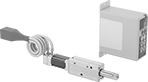
Low-Profile Electric Positioning Slides with Automated Controls

Less than one-third the height of standard electric positioning slides, these slides push and pull small parts in electronics manufacturing, robotics, and other automated processes. They have a magnetic linear motor to generate fast and precise motion while taking up only a tiny footprint. With a controller and driver also included, they’re an all-in-one actuation system. Use them where extreme precision is needed—they have a repeatability of ±0.5 microns, which is 1/50,000th of an inch.
Download free CME2 software during initial setup for easy, point-and-click programming. Controllers using CME2 can store and run sequences of up to 32 steps. For added speed and flexibility, these slides are also compatible with CPL, used to write advanced custom programs.
Dynamic load capacity is the maximum load slides can move. If you increase the speed, the dynamic load capacity decreases. Use a load-speed chart to confirm which slides will work for your application. Click on a part number and select "Product Detail" to view the chart.
Overall | Carriage | ||||||||||||||
|---|---|---|---|---|---|---|---|---|---|---|---|---|---|---|---|
| Lg., mm | Wd., mm | Ht., mm | Lg., mm | Wd., mm | Bearing Type | Dynamic Horizontal Load Capacity, lbs. | Max. Speed, mm/s | Travel Distance per Full Step, mm | Repeatability, microns | Base Material | Full Load Current | Voltage | Operating System Compatibility | Each | |
10 mm Stroke Length | |||||||||||||||
| 62 | 38 | 11 | 38 | 26 | Ball | 1 | 500 | 0.0005 | ±0.5 | Nickel-Plated Steel | 3A | 24V DC | Windows 10 or Later | 0000000 | 000000000 |
18 mm Stroke Length | |||||||||||||||
| 86 | 38 | 11 | 54 | 26 | Ball | 1 | 500 | 0.0005 | ±0.5 | Nickel-Plated Steel | 3A | 24V DC | Windows 10 or Later | 0000000 | 00000000 |
25 mm Stroke Length | |||||||||||||||
| 120 | 55 | 14 | 80 | 48 | Ball | 11 | 1,300 | 0.0005 | ±0.5 | Nickel-Plated Steel | 1.2A | 48V DC | Windows 10 or Later | 0000000 | 00000000 |
| 120 | 80 | 16 | 80 | 68 | Ball | 11 | 1,300 | 0.0005 | ±0.5 | Nickel-Plated Steel | 1A | 48V DC | Windows 10 or Later | 0000000 | 00000000 |
65 mm Stroke Length | |||||||||||||||
| 160 | 55 | 14 | 80 | 48 | Ball | 11 | 1,300 | 0.0005 | ±0.5 | Nickel-Plated Steel | 2.4A | 48V DC | Windows 10 or Later | 0000000 | 00000000 |
| 160 | 80 | 16 | 80 | 68 | Ball | 11 | 1,300 | 0.0005 | ±0.5 | Nickel-Plated Steel | 2.1A | 48V DC | Windows 10 or Later | 0000000 | 00000000 |
120 mm Stroke Length | |||||||||||||||
| 280 | 80 | 16 | 140 | 68 | Ball | 11 | 1,300 | 0.0005 | ±0.5 | Nickel-Plated Steel | 2.1A | 48V DC | Windows 10 or Later | 0000000 | 00000000 |
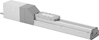
Low-Temperature Electric Positioning Slides

Precisely position parts in conditions as cold as -90° F. These slides contain a grease that lubricates even in low temperatures. With an integrated stepper motor, they’re a complete motion control system for automated assemblies. A controller is included, so you can adjust the speed, timing, and positioning with no extra software required. These slides are often used in actions that require fine, repeatable movement, such as drilling, fastening, assembly, and measuring. The carriage extends the same distance every time within ±0.02 mm, a margin thinner than a sheet of paper.
Dynamic load capacity is the maximum load slides can move. If you increase the speed, the dynamic load capacity decreases. Use a load-speed chart to confirm which slides will work for your application. Click on a part number and select "Product Detail" to view the chart.
Travel distance per full step determines the control you have over the slide’s positioning. The smaller the measurement, the finer positioning control you have.
Travel distance per turn, also known as screw lead, is how far the carriage moves with one rotation of the ball screw.
Dynamic Load Capacity, lbs. | Travel Distance per | Overall | Carriage | |||||||||||||
|---|---|---|---|---|---|---|---|---|---|---|---|---|---|---|---|---|
| Horizontal | Vertical | Max. Speed, mm/s | Full Step, mm | Turn, mm | Repeatability, mm | Lg., mm | Wd., mm | Ht., mm | Lg., mm | Wd., mm | Bearing Type | Base Material | Full Load Current | Voltage | Each | |
100 mm Stroke Length | ||||||||||||||||
| 44 | 16 | 500 | 0.06 | 12 | ±0.02 | 336 | 60 | 57.5 | 102 | 50 | Roller | Aluminum | 2.4A | 24V DC | 0000000 | 000000000 |
200 mm Stroke Length | ||||||||||||||||
| 44 | 16 | 500 | 0.06 | 12 | ±0.02 | 436 | 60 | 57.5 | 102 | 50 | Roller | Aluminum | 2.4A | 24V DC | 0000000 | 00000000 |
| 88 | 22 | 250 | 0.08 | 16 | ±0.02 | 482 | 70 | 79 | 122 | 60 | Roller | Aluminum | 5.2A | 24V DC | 0000000 | 00000000 |
300 mm Stroke Length | ||||||||||||||||
| 44 | 16 | 500 | 0.06 | 12 | ±0.02 | 536 | 60 | 57.5 | 102 | 50 | Roller | Aluminum | 2.4A | 24V DC | 0000000 | 00000000 |
400 mm Stroke Length | ||||||||||||||||
| 88 | 22 | 250 | 0.08 | 16 | ±0.02 | 682 | 70 | 79 | 122 | 60 | Roller | Aluminum | 5.2A | 24V DC | 0000000 | 00000000 |
600 mm Stroke Length | ||||||||||||||||
| 88 | 22 | 250 | 0.08 | 16 | ±0.02 | 882 | 70 | 79 | 122 | 60 | Roller | Aluminum | 5.2A | 24V DC | 0000000 | 00000000 |