


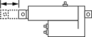
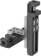
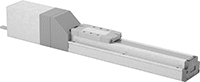
Positioning Slides for Stepper Motors
Add your own stepper motor and controller to precisely move the ball screw and carriage smoothly at high speeds, like a head on an inkjet printer. With a repeatability of ± 0.01 mm—thinner than a strand of hair—the carriage hits the same spot every time. These positioning slides work well for automated assemblies and other applications that require fine, repeatable motion control.
The carriage rides along the inside of the rail, making these slides more compact than traditional carriages and guide rails. Made of steel with a U-shaped rail, these slides resist twisting forces that could affect their positioning. This also means they can be installed with only one end supported or with both ends overhanging. The same load rating applies no matter how the slides are oriented.
Two-axis mounting plates (sold separately) secure two slides together for motion along two axes.
Travel distance per turn, also known as screw lead, is how far the carriage moves with one rotation of the ball screw.
![]() For technical drawings and 3-D models, click on a part number.
For technical drawings and 3-D models, click on a part number.
Dynamic Load Capacity, lbs. | Overall | Carriage | |||||||||||||||
|---|---|---|---|---|---|---|---|---|---|---|---|---|---|---|---|---|---|
| Stroke Lg., mm | Horizontal | Vertical | Max. Speed, mm/s | Travel Distance per Turn, mm | Repeatability, mm | For Shaft Dia. | For Max. Motor Speed, rpm | For Max. Motor Torque, in.-oz. | Lg., mm | Wd., mm | Ht., mm | Lg., mm | Wd., mm | Bearing Type | Base Material | Each | |
For NEMA 23 Motor Frame Size | |||||||||||||||||
| 300 | 395 | 395 | 790 | 10 | ±0.01 | 1/4" | 6,000 | 176 | 480 | 60 | 56.4 | 76 | 37.4 | Ball | Steel | 00000000 | 000000000 |
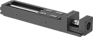
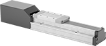
Dry-Running Positioning Slides for Stepper Motors
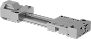
With PTFE sleeve bearings and a low-friction ball screw, these slides don’t require the mess and maintenance of lubrication but still give you precise positioning anywhere along the length of their stroke. Because they have sleeve bearings, they have fewer moving parts, so they perform better in dusty and wet environments than slides with ball bearings. They’re also better at handling impact and vibration.
All slides require a stepper motor, driver, and controller (not included) to operate. As part of this system, they move in precise increments, like the head on an inkjet printer. These positioning slides work well for automated assemblies and other applications that require fine, repeatable motion control.
Travel distance per turn, also known as screw lead, is how far the carriage moves with one rotation of the ball screw.
![]() For technical drawings and 3-D models, click on a part number.
For technical drawings and 3-D models, click on a part number.
Overall | Carriage | ||||||||||||||||
|---|---|---|---|---|---|---|---|---|---|---|---|---|---|---|---|---|---|
| Stroke Lg., mm | Dynamic Horizontal/Vertical Load Capacity, lbs. | Static Load Capacity, lbs. | Max. Speed, mm/s | Travel Distance per Turn, mm | Repeatability, mm | For Shaft Dia. | For Max. Motor Speed, rpm | For Max. Motor Torque, in.-oz. | Lg., mm | Wd., mm | Ht., mm | Lg., mm | Wd., mm | Bearing Type | Base Material | Each | |
For NEMA 17 Motor Frame Size | |||||||||||||||||
| 300 | Not Rated | 630 | 50 | 2 | ±0.1 | 5mm | 1,500 | 71 | 476 | 74 | 56 | 69 | 73 | Sleeve | Aluminum | 0000000 | 0000000 |
For NEMA 23 Motor Frame Size | |||||||||||||||||
| 300 | Not Rated | 630 | 50 | 2 | ±0.1 | 1/4" | 1,500 | 283 | 477 | 74 | 56 | 69 | 73 | Sleeve | Aluminum | 0000000 | 000000 |
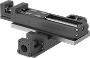
Electric Positioning Slides with Automated Controls

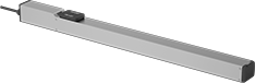
With an included controller and an integrated stepper motor, these slides are a complete precision motion control system. The stepper motor moves the low-friction ball screw and carriage smoothly at high speeds, similar to an inkjet printer head. To make sure the carriage is in the right place, the built-in encoder sends data to the controller. At ± 0.02 mm, these slides have a repeatability thinner than a single strand of hair, so the carriage hits the same spot every time. They work well in automated assemblies and other processes requiring accurate, repeatable motion.
For the initial setup, program the slides using the free, downloadable software, THK D-STEP. No coding necessary—simply enter the target position, speed, and acceleration for up to 16 different slides. This software also records position, speed, and motor current data, so you can monitor performance, optimize motion, and troubleshoot issues.
After the initial setup, the controller stores and runs sequences of up to 512 unique steps on its own. The controller also communicates with other devices such as PLCs, switches, and sensors. This means it can be integrated into a larger automated system to react to or trigger other processes as the carriage moves.
Travel distance per turn, also known as screw lead, is how far the carriage moves with one rotation of the ball screw.
Dynamic load capacity is the maximum load slides can move. If you increase the speed, the dynamic load capacity decreases. Use a load-speed chart to confirm which slides will work for your application. Click on a part number and select "Product Detail" to view the chart.
![]() For technical drawings and 3-D models, click on a part number.
For technical drawings and 3-D models, click on a part number.
Dynamic Load Capacity, lbs. | Overall | Carriage | ||||||||||||||
|---|---|---|---|---|---|---|---|---|---|---|---|---|---|---|---|---|
| Horizontal | Vertical | Max. Speed, mm/s | Travel Distance per Turn, mm | Repeatability, mm | Lg., mm | Wd., mm | Ht., mm | Lg., mm | Wd., mm | Bearing Type | Base Material | Full Load Current | Voltage | Operating System Compatibility | Each | |
300 mm Stroke Length | ||||||||||||||||
| 2 | 1 | 300 | 6 | ±0.02 | 546 | 32 | 39 | 66.4 | 28 | Ball | Aluminum | 1.5A | 24V DC | Windows XP or Later | 0000000 | 000000000 |
| 13 | 4 | 500 | 12 | ±0.02 | 556 | 50 | 55 | 71 | 44 | Ball | Aluminum | 1.5A | 24V DC | Windows XP or Later | 0000000 | 00000000 |
| 22 | 11 | 300 | 6 | ±0.02 | 556 | 50 | 55 | 71 | 44 | Ball | Aluminum | 1.5A | 24V DC | Windows XP or Later | 0000000 | 00000000 |
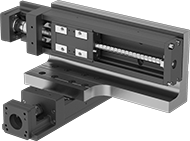
Clean Room Electric Positioning Slides
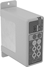
Prevent dust from circulating while precisely positioning parts for drilling, fastening, assembly, and measuring. These slides have a built-in vacuum port to remove fine particles that could damage electronics or contaminate batches in clean rooms. Because they have an integrated stepper motor with an included controller, you can adjust the speed, timing, and positioning with no extra software required. At ± 0.02 mm, these slides have a repeatability thinner than a single sheet of paper, so the carriage hits the same spot every time. Unlike air-powered actuators, they’ll hold their position even if power fails. They’re also more energy efficient.
Dynamic load capacity is the maximum load slides can move. If you increase the speed, the dynamic load capacity decreases. Use a load-speed chart to confirm which slides will work for your application. Click on a part number and select "Product Detail" to view the chart.
Maximum speed is how fast the slide will move under no-load conditions. If you increase the load, the slide speed will decrease.
Travel distance per full step determines the control you have over the slide’s positioning. The smaller the measurement, the finer positioning control you have.
Travel distance per turn, also known as screw lead, is how far the carriage moves with one rotation of the ball screw.
![]() For technical drawings and 3-D models, click on a part number.
For technical drawings and 3-D models, click on a part number.
Dynamic Load Cap., lbs. | Travel Distance per | Overall | Carriage | ||||||||||||||
|---|---|---|---|---|---|---|---|---|---|---|---|---|---|---|---|---|---|
| Horizontal | Vertical | Max. Speed, mm/s | Full Step, mm | Turn, mm | Repeatability, mm | Lg., mm | Wd., mm | Ht., mm | Lg., mm | Wd., mm | Bearing Type | Base Material | Full Load Current | Voltage | Environmental Rating | Each | |
300 mm Stroke Length | |||||||||||||||||
| 110 | 44 | 250 | 0.08 | 8 | ±0.02 | 641 | 70 | 84 | 122 | 60 | Ball | Aluminum | 5A | 24V DC | Fed. Std. Class 10, ISO Class 4 | 0000000 | 000000000 |
Low-Temperature Electric Positioning Slides

Precisely position parts in conditions as cold as -90° F. These slides contain a grease that lubricates even in low temperatures. With an integrated stepper motor, they’re a complete motion control system for automated assemblies. A controller is included, so you can adjust the speed, timing, and positioning with no extra software required. These slides are often used in actions that require fine, repeatable movement, such as drilling, fastening, assembly, and measuring. The carriage extends the same distance every time within ±0.02 mm, a margin thinner than a sheet of paper.
Dynamic load capacity is the maximum load slides can move. If you increase the speed, the dynamic load capacity decreases. Use a load-speed chart to confirm which slides will work for your application. Click on a part number and select "Product Detail" to view the chart.
Travel distance per full step determines the control you have over the slide’s positioning. The smaller the measurement, the finer positioning control you have.
Travel distance per turn, also known as screw lead, is how far the carriage moves with one rotation of the ball screw.
![]() For technical drawings and 3-D models, click on a part number.
For technical drawings and 3-D models, click on a part number.
Dynamic Load Capacity, lbs. | Travel Distance per | Overall | Carriage | |||||||||||||
|---|---|---|---|---|---|---|---|---|---|---|---|---|---|---|---|---|
| Horizontal | Vertical | Max. Speed, mm/s | Full Step, mm | Turn, mm | Repeatability, mm | Lg., mm | Wd., mm | Ht., mm | Lg., mm | Wd., mm | Bearing Type | Base Material | Full Load Current | Voltage | Each | |
300 mm Stroke Length | ||||||||||||||||
| 44 | 16 | 500 | 0.06 | 12 | ±0.02 | 536 | 60 | 57.5 | 102 | 50 | Roller | Aluminum | 2.4A | 24V DC | 0000000 | 000000000 |